
Bosch VP44 Injection Pump Replacement
Removal
1. Disconnect both negative battery cables at both batteries. Cover and isolate ends of cables.
2. Thoroughly clean fuel lines at cylinder head and injection pump ends. Thoroughly clean Bosch VP44 injection pump and supply/return lines at side of pump.
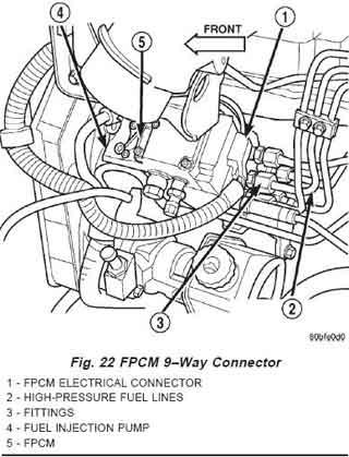
3. Disconnect 9–way electrical connector at Fuel Pump Control Module (FPCM) (Fig. 22).
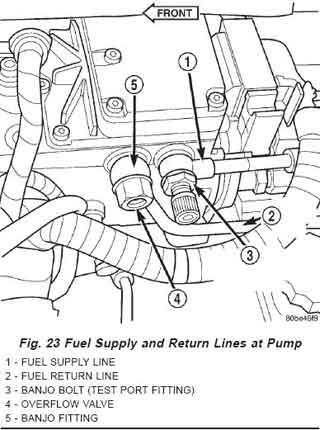
4. Remove fuel return line at side of Bosch VP44 injection pump by removing overflow valve (Fig. 23). Place rag beneath overflow valve to catch excess fuel.
5. Remove fuel supply line at side of Bosch VP44 injection pump by removing banjo bolt (Fig. 23). Also remove same line at top of fuel filter housing (banjo bolt).
6. Remove all high-pressure fuel lines, intake air tube, accelerator pedal position sensor, air intake housing, engine oil dipstick tube, wiring clips, electrical cables at intake heaters and engine lifting bracket.
a. Remove the APPS sensor. Just unbolt the APPS and unhook the wires and tuck it back towards the firewall with the throttle cable attached.
b. Remove the intake elbow 4 bolts and remove the air pipe on the driver side. As for the dipstick tube it can be move out of the way by twisting it carefully.
c. Remove grid heater leaving the wires attached to the grid heater and tuck back out of the way.Mopar's Notes: Now you only need to remove 1,2,4 high pressure injector lines. The other 3,5,6 can remain attached to the engine but need to be removed from the Bosch VP44 injection pump.
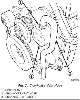
7. Remove hose clamp at crankcase vent hose (Fig. 24) and remove the hose from the canister.
8. Remove (unscrew - right-hand thread) canister (Fig. 24) from gear cover.
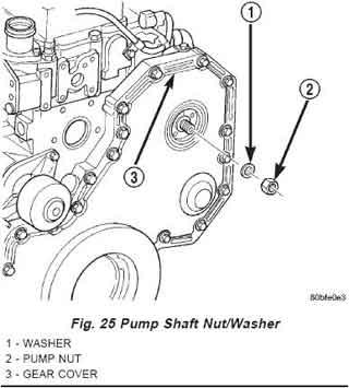
9. Remove nut and washer retaining injection pump gear to Bosch VP44 injection pump shaft (Fig. 25)
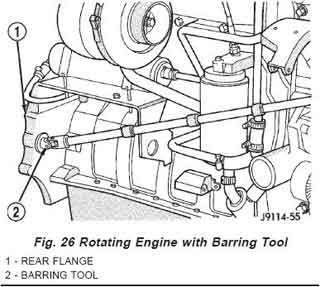
10. The engine can be rotated with a barring tool such as Snap-On No. SP371, MTE No. 3377371 (Cummins Tool Division, or an equivalent. The opening for barring tool is located in rear flange of the engine on exhaust manifold side (Fig. 26). Remove rubber access plug covering this opening. A 15/16" socket on the alternator can be used as a barring tool.
11. Insert barring tool into flywheel housing opening (Fig. 26).
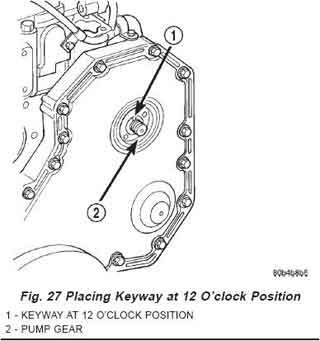
12. Rotate engine until keyway is at 12 o’clock position (Fig. 27).
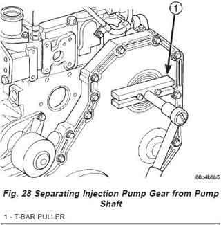
13. Use T-bar type puller (Fig. 28) to separate injection pump gear from Bosch VP44 injection pump shaft. Attach two M8 X 1.24 MM (metric) screws through puller and into two threaded holes supplied in pump gear. Pull injection pump gear forward until it loosens from injection pump shaft. Pull on gear only enough to loosen it from the injection pump shaft. Pulling gear too far may cause damage or breakage to gear cover.
14. Remove 2 rear/lower pump bracket bolts (Fig. 29).
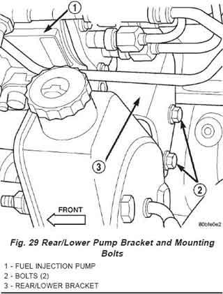
15. Remove 4 Bosch VP44 injection pump-to-gear housing mounting nuts.
16. Remove Bosch VP44 injection pump from gear housing. Take care not to nick injection pump shaft on aluminum gear housing when removing the pump. Also, be very careful not to drop pump keyway into gear housing.
WARNING: Whenever the Bosch VP44 fuel injection pump is removed from the engine, the pump drive gear is laying loose on the camshaft drive gear. Never attempt to crank or rotate the engine with the pump removed from the engine. Serious damage will occur.
To prevent pump/gear keyway from falling into gear housing, the engine must be rotated until keyway is at 12 o’clock position (Fig. 27). If gear retainer nut, washer or key drops into gear housing, the cover may have to be removed to retrieve them before the engine is started.
Installation
1. Inspect pump mounting surfaces at the pump and the mounting flange for nicks, cuts or damage. Inspect o-ring surfaces for nicks, cuts or damage.
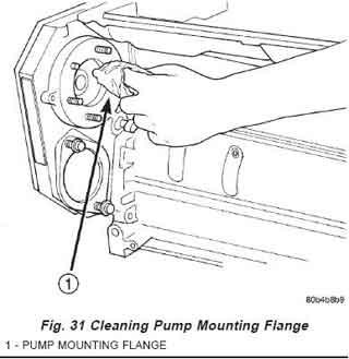
2. Clean injection pump mounting flange (Fig. 31) at gear housing. Also the clean front of the injection pump.
3. Install new rubber o-ring (Fig. 33) at pump mounting area.
4. Apply clean engine oil to the injection pump o-ring only. The machined tapers on both injection pump shaft and injection pump gear (Fig. 34) must be absolutely dry, clean and free of any dirt or oil film. This will ensure proper gear-to-shaft tightening.
5. Clean pump gear and pump shaft at machined tapers (Fig. 34) with an evaporative type cleaner such as brake cleaner.
Keyway Installation:
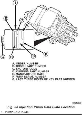
6. The pump/gear keyway has an arrow and a 3–digit number stamped at top edge (Fig. 33). Position keyway into pump shaft with the arrow pointed to the rear of the pump. Also be sure 3–digit number stamped to top of keyway is same as 3–digit number stamped to injection pump data plate (Fig. 35). If wrong keyway is installed, a diagnostic trouble code may be set.
Mopar's Notes: A suggestion is once you ready to place the key in the shaft take a few drops of super glue and glue it in place. This will keep the key from falling out during installation of the pump.
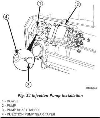
7. Position Bosch VP44 injection pump assembly to mounting flange on gear cover while aligning Bosch VP44 injection pump shaft through back of injection pump gear. When installing pump, dowel (Fig. 34) on mounting flange must align to hole in front of pump.
8. After Bosch VP44 injection pump is positioned flat to mounting flange, install four pump mounting nuts and tighten finger tight only. Do not attempt a final tightening at this time. Do not attempt to tighten (pull) Bosch VP44 injection pump to gear cover using mounting nuts. Damage to pump or gear cover may occur. The pump must be positioned flat to its mounting flange before attempting to tighten mounting nuts.
9. To prevent damage or cracking of components, tighten nuts/bolts in the following sequence:
a. Install Bosch VP44 injection pump shaft washer and nut to pump shaft. Tighten nut finger tight only.
b. Install 2 rear/lower pump mounting bolts finger tight only.
c. Do preliminary tightening of Bosch VP44 injection pump shaft nut to 30 N·m (15–22 ft. lbs.) torque. This is not the final torque.
d. Tighten 4 Bosch VP44 injection pump mounting nuts to 43 N·m (32 ft. lbs.) torque.
e. Tighten 2 rear/lower Bosch VP44 injection pump bracket-to-pump bolts 24 N·m (18 ft. lbs.) torque.
f. Do final tightening of Bosch VP44 injection pump shaft nut to 170 N·m (125 ft. lbs.) torque. Use barring tool to prevent engine from rotating when tightening gear.
10. Install canister (Fig. 24) to gear cover.
11. Install crankcase vent hose (Fig. 24) to canister and install hose clamp.
12. Using new gaskets, install fuel return line and overflow valve to side of Bosch VP44 injection pump (Fig. 23). Tighten overflow valve to 24 N·m (18 ft. lbs.) torque.
13. Using new gaskets, install fuel supply line to side of Bosch VP44 injection pump and top of fuel filter housing (Fig. 23). Tighten banjo bolts to 24 N·m (18 ft. lbs.) torque.
14. Install all high-pressure fuel lines, intake air tube, accelerator pedal position sensor, air intake housing, engine oil dipstick tube, wiring clips, electrical cables at intake heaters and engine lifting bracket. Tighten the fuel line(s) at the head to the injector connector(s) to 38 N·m (28 ft. lbs.) torque.
15. Connect 9–way electrical connector to Fuel Pump Control Module (FPCM) (Fig. 22).
16. Connect both negative battery cables to both batteries.
17. Bleed air from fuel system.
18. Check system for fuel or engine oil leaks.