
I don't do much on the forums anymore, but I thought somebody might benefit from documenting what I consider a proper radio installation for a 2nd generation Ram. Honestly it will probably be almost identical for any extended cab Ram. I purposely built this using materials anybody can get from the big box stores and truck stop radio supplies.
Materials List:
Qty 1: 3/4 in. x 36 in. Plain Steel Square Tube with 1/16 in. Thick
Qty 1: 1 in. x 36 in. Plain Steel Flat Bar with 1/8 in. Thick
Qty 1: 2 in. x 36 in. Plain Steel Flat Bar with 1/8 in. Thick
Qty 1: 6 in. x 18 in. 16-Gauge Plain Steel Sheet Metal
Qty 2: M8 1.25 20mm Bolt
Qty 2: M8 1.25 Nut
Qty 2: M8 Flat Washer
Qty 2: 5/16 x 3/4" Bolt
Qty 1: Wilson 305-830 18' Belden Coax Cable with PL-259/FME Connectors
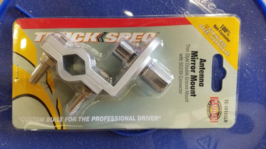
Qty 1: TruckSpec TS-101ADLN Thin Double Groove Mirror Mount with SO-239 Stud Connector
Qty 1: 1/4" Split wire loom
Qty 1: 3/8" Rubber Insulated Metal Clamp
Qty 1: 6" Zip Tie (yes only one)
Qty 1: #8 x 3/4" Phillips Washer HD Tapping Screw Balkamp 665-2837
Qty 1: FireStik K-1A Push-n-Twist quick disconnect (this is required)
Starting with the antenna:
3' Firestik II
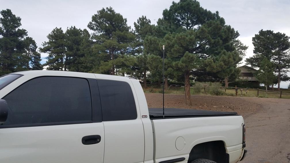
Looking down the stake pocket:

What the antenna mount looks like. You will be tempted to buy the larger four bolt mount. Don't as you can not get it in the pocket. Even this little guy takes some fiddling to get it down there. In the item list are two 5/6" bolts. This is part of the trick getting everything to fit. Separate the clamp, then you have to tap the antenna side holes to accept the 5/16" bolt. This serves two purposes. 1. You have zero chance of getting a nut on a bolt inside the stake pocket. 2. It reduces the possibility of hardware physically interfering with the coax. Things are tight in there. To make this work you have to assemble the now threaded mount, the firestik quick connect and the coax in one shot. Anything that has to be tightened to the mount must be done so prior to dropping it into the stake pocket.
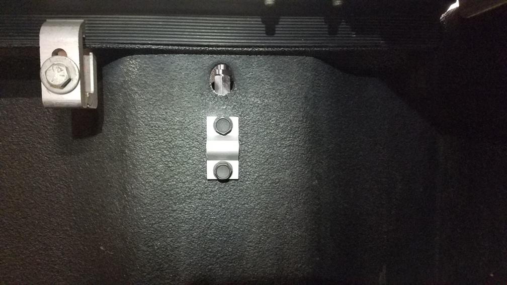
Here comes the painful part. Drilling holes. These are the very first holes I have ever drilled in this truck. Antennas are about the only reason I will punch a hole in a vehicle. Per the picture you can see I used the outer clamp from the bracket. This serves a couple purposes. 1. Expands the clamping area to provide better support for the mast and reducing the possibility of metal fatigue. If you don't have a bed liner grounding will also be improved. 2. It acts as a spacer to keeping the bolt protrusion to a minimum. Use a step drill bit anytime you are drilling sheet metal. Much cleaner holes. The holes are over sized in the bed to provide adjust-ability to aid vertical antenna placement. Drill the top hole first. Attach the bolt and clamp on the inside of the bed. Use that to locate where the bottom hole should be located. Then drill the bottom hole.
Now we have to think about coax routing. You will be tempted to route the coax through the oval opening to the outside of the bed. This could be done, but I don't recommend it. At least not using the coax I identified in the material list. It is good coax, and has a really good strain relief boot for the antenna end. It doesn't want to make that initial turn easily. You might consider a 90 degree connector except you can not get the coax, connector and the mount installed and slid into the pocket.
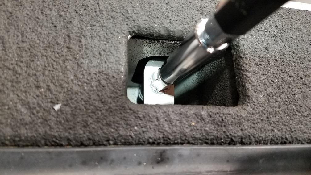
My solution? Another hole... and you already know I don't take that lightly. BUT... there is one upside. If you set your mount at the same height or even a little lower as I did that heavy duty boot on the coax slides right into that hole. You will also notice some discoloration around the bottom of the stake pocket. That is a white paint marker. Every hole gets deburred and paint applied. I got to the bottom of that stake pocket blind since I'm not a contortionist and have a fat head. The end result is a nice straight coax run.
So I'm up to three holes so far. What's one more between friends... Cables should be secure. If left to flop around at best they break. At worst (in my opinion) they chafe on body structures eventually removing paint and then promoting corrosion. Drill a hole for the cable clamp. Secure with a nice #8 body screw. That is the last hole for this project. (I lied, there are two more)
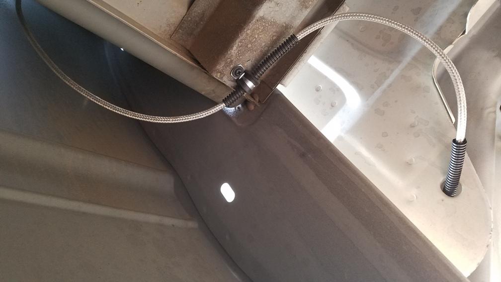
Picture shows the transission from the bed to the cab. Nice gentle loops were made. The split loom stays static allowing the coax to move within it, but the coax will not be moving.

Pic at the very back of the cab. Route coax through support structure. Add split loom
Picture of the coax routed through the very front cab support brace before it makes a turn to head up towards the entry point in the A pillar. Add a zip tie to the emergency brake cable.

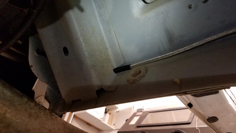
Picture of the coax exiting the front support brace and making the turn up towards the entry in the A pillar. Single piece of split loom is used here all the way up to the entry point.
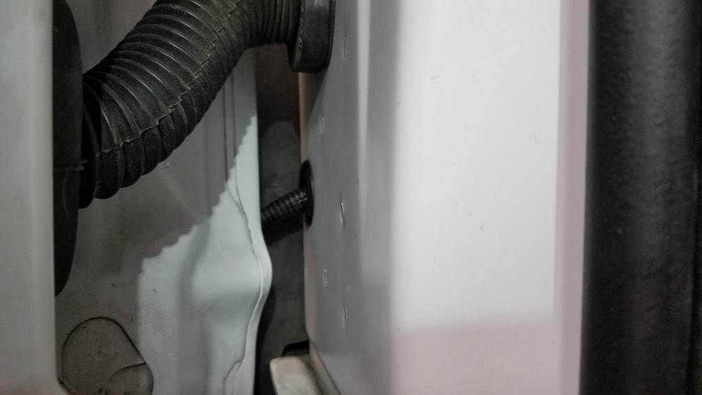
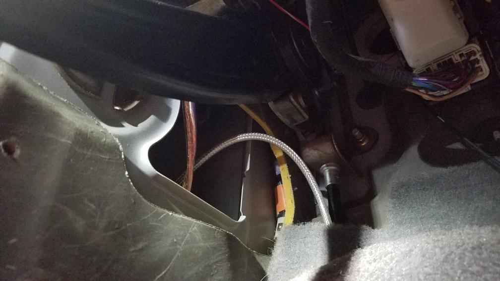
Trying to get a good shot of where it enters the cab is challenging. But there is a body plug below the the main door wire harness. The plug can be easily accessed by removing the interior kick panel cover. Highly recommend using a 5/16" hollow punch to make the hole in the body plug. This makes a clean tight hole for the coax to run through.
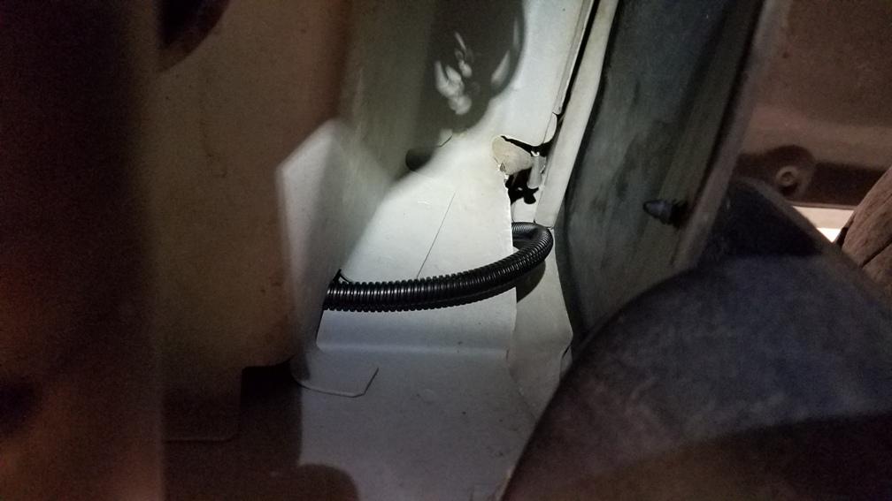
Picture of the coax finally making its way into the cab. Not pictured, but add split loom where it will be pressed against the notch in the sheet metal. I added it until it met the carpet. makes it look a little more factory.
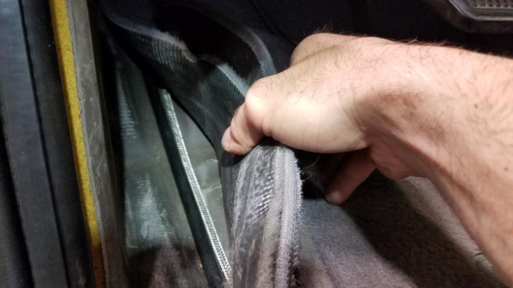
From there route the coax to the interior side of the emergency brake cable under the carpet.
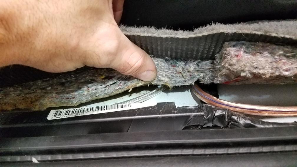
Continue keeping the coax to the interior side of the factory wire loom. Pictured is where the coax runs back to about the center of the front seat and makes its turn for the center of the truck.
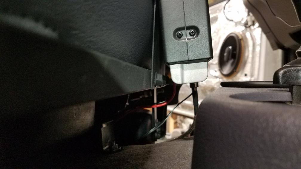
Picture of coax exiting under the drivers seat with the factory wiring, and my sub-woofer speaker wire.
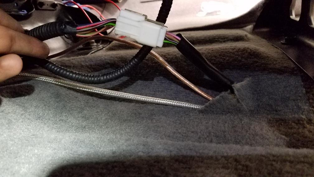
Finally here is the end of the run. Run the wire under the center section of the drivers side seat frame then you are ready to terminate on the radio. Routing the coax this way eliminated sharp bends. It is secure. Best of all it uses all 18' of coax. No excess coils tucked away somewhere.

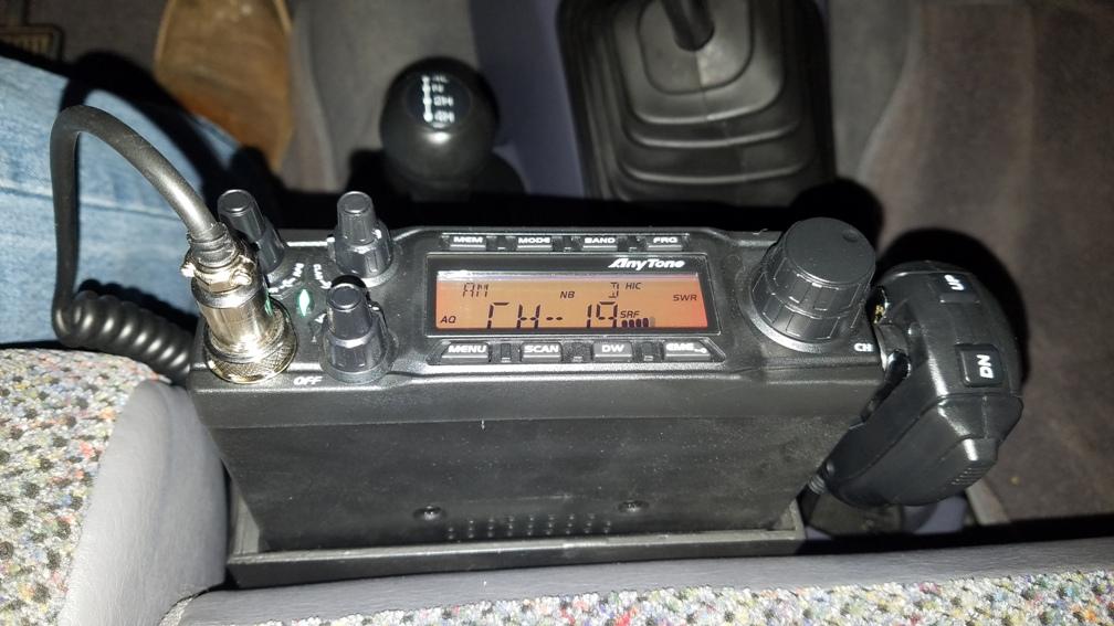
So at this point you saw a glimpse of the radio mount. Here is a better shot. Unfortunately I misplaced the pictures of the mount before it was installed. Here is a shot from the passenger side.
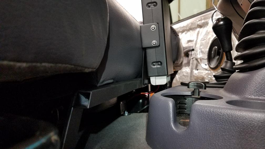
On both seat mounts there are two holes in the inboard rails. On my passenger seat there is an existing bar tying the inboard and outboard rails together. I utilized the factory hardware to attach the 1" vertical flat bar. I removed that cross bar so I could use a transfer punch to get the hole locations in the 1" flat bar. You could just as easily hold the bar in place and mark from the rear with a sharpie.

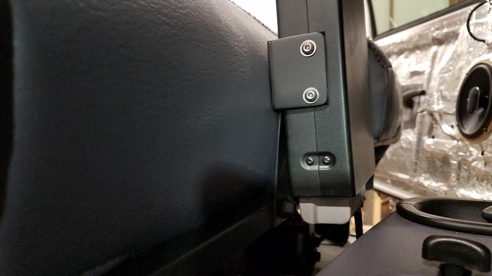
Now onto the radio mount plate. This is also where customization occurs depending on personal preferences radios, etc. My design allows for this. You will notice I used three bolts to secure the 16ga sheet metal. The idea is most anybody I know whom is into radios change them out frequently. Using a mechanical fastner here allows different plates to be made for any radio or preference. The plate can even remain with the radio since the bolts are spaced one inch from the edge and one in the center. No trial fitments for new plates.
Radio mount bracket. You might be tempted to try and bend the flat bar to the desired dimensions. Unless you do that for a living don't even try it. Using the 2" flat bar I cut the tabs to the desired height, and the base to the desired width. I drilled the tab mount holes. Then I silver soldered them together. Yeah everything you see that doesn't have a visible fastener was silver soldered. It was kind of fun going that route. Don't like how a tab sits? Made a bad measurement? Little bit of heat and you take it off and make another. Something not quite straight, or maybe you want to angle the radio more than you thought. Little heat, and re-position. I have access to MIG and TIG, and can tell you silver soldering is a pretty good route to fabricate with. So the bracket is all 2" flat bar. That gets built as a unit. then I silver soldered that to the 16ga sheet metal. I placed a small bend in the sheet metal where they join. I did this to place the radio within easy reach (my hand almost falls right on it). It also improves the readability of the display. I debate on if I put enough angle on it, but I will probably leave it as is.
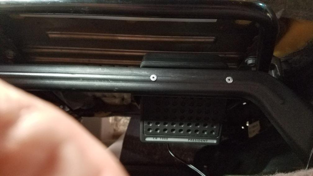
For the grand finale? I mounted a remote speaker under the passenger seat. I cut a section of the 3/4" square tube long enough to match the speaker mount. The tube fits inside the brace U channel providing a square surface for the speaker mount to attach to. I decided to attach the square tube with 1/8" steel pop rivets. Drill the brace from the rear in order to hit the center of the rib. In the picture you can tell the right rivet head was peened. In the end both were peened and then painted. I wanted a smooth fastener so passengers couldn't catch a finger on a screw or bolt head.
Well maybe a few more parting shots.

73 Everybody.
-
 1
1
-
 3
3