
Review Monitor
Cab Monitor and Rear Trailer Camera
Parts list:
50’ roll outdoor Cat-5/Cat-6 cable (Home Depot)
10’ red 18awg
1’ black 18awg
10 ‘split wire loam tubing ¼ diam.
5” color monitor (5” E-KLIN 12-24V car monitor, Amazon)
Color camera (E SKY EC170-11, Amazon)
4 pin round trailer wire connector
ON/OFF switch, SPST, push or toggle
2 amp fuse
Fuse holder
Rosin core solder
Electrical tape
Heat shrink tubing
Coaxial cable staples
Zip ties
2”x4”x ½”- ¾” plywood or board
Flat black spray paint
Double sided tape or 3M auto molding tape
Clear silicone adhesive
3 #6x ½” screw
1 #8 ring terminal 22-18awg
Tools:
Wire cutter
Wire stripper
Pliers
Solder gun
Small blade screwdriver
Phillips screwdriver
Drill motor
Drill bits ⅛ - ⅜”
Hole saw 1⅜”
Hammer
This system was put together in the spring of 2017 and has been used for over 20,000 miles with no problems. It cost about $80 for the cable, monitor, switch, round 4 pin trailer connector, and camera. The rest of the parts and materials I had on hand. I put in the ON/OFF switch so the monitor can be turned off for night driving.
Note: Cameras with inferred night vision may not work well at night if the camera is placed inside the trailer and viewing through glass without outside lighting.
Installing Camera and Trailer Wiring
First, locate a suitable mounting position for the camera. A rear facing window is ideal and if there is a cabinet next to it the wire connections can be hidden in it. If a rear window is not available a hole drilled through the rear wall next to where the camera will be mounted or the cable run under the trailer and up the outside of the rear wall is an option.
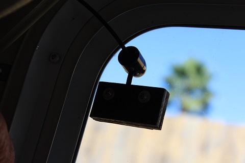
Camera mounted in rear trailer window.
Run the Cat-5 cable through the trailer from next to the trailer’s seven pin connector, in front, to where the camera’s mounting position will be, leaving 6”-12” of extra cable at the ends, If you have 20’ of cable left you can use it for the truck installation otherwise you will need to buy more. You can drill holes, just big enough, in the walls and floor to pass the cable through. When drilling through the floor be careful not to drill into a holding tank, waterline, or anything else; drilling into an empty storage compartment is best. The Cat-5 cable can be held in place with coaxial cable staples for the walls and zip ties elsewhere.
The Cat-5 cable has four sets of 2-24awg: orange, green, blue, and brown. I used the orange set for 12volt feed, the green for the ground, the blue for video signal, and connected the shielding wires from the camera and monitor to the brown. 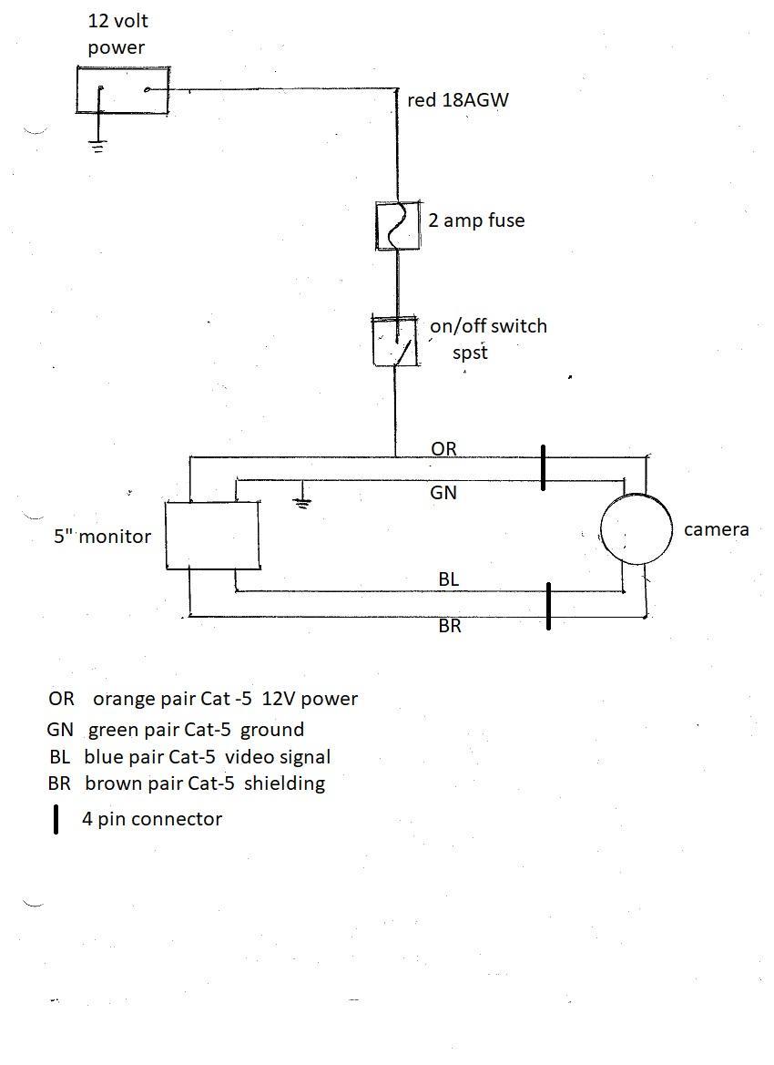
Spray paint the wood black and let dry, attach the camera to the wood with the 2 #6x ½” screws. Solder camera’s: power wire to the Cat-5 orange wires, ground wire to the Cat-5 green wires, video to the Cat-5 blue wires and shielding to the Cat-5 brown pair; sealing each solder joint with heat shrink then wrap cable junction with electrical tape. If the camera is next to a cabinet you can run the wires through a hole drilled in its bottom or side and place connection in the cabinet for concealment. Now, place the two sided tape on the wood and carefully affix it to the window with the camera facing out. Camera view adjustment will be done after the monitor is functional.
Installing Monitor and Cab Wiring
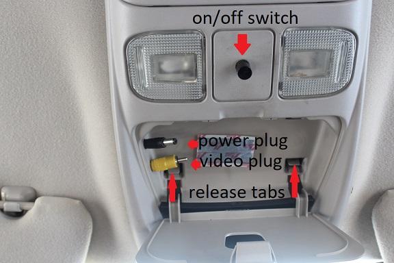
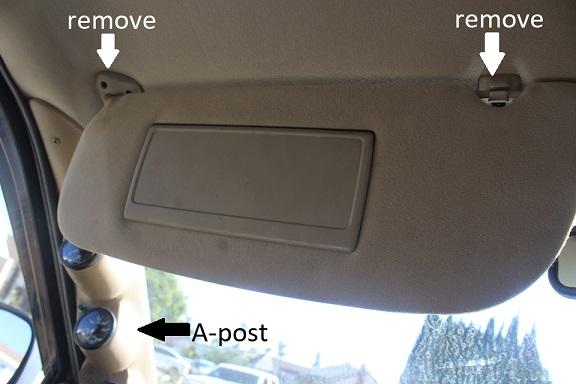
In the truck cab remove the overhead light counsel and drill two holes in it, see picture; one for the monitor power cable and one for the monitor video cable. Do not remove the cover for the garage door remote pocket, just open it up and remove the square button; you will be passing the cable from the monitor though here. You can install the ON/OFF switch in this area at this time or locate a place that is to your liking. Find the roof bracing and drill a small hole for a short screw that the systems ground wire will be attached to. DO NOT drill through the roof.
Find a wire that has switched power to splice into for the systems power. Power draw is about 1amp. Add a 2amp fuse to the red wire and spliced it to the tan wire at the large connector under the left side of the dash between he park brake pedal and the firewall. This tan wire is rated 20amps and is used for the power windows.
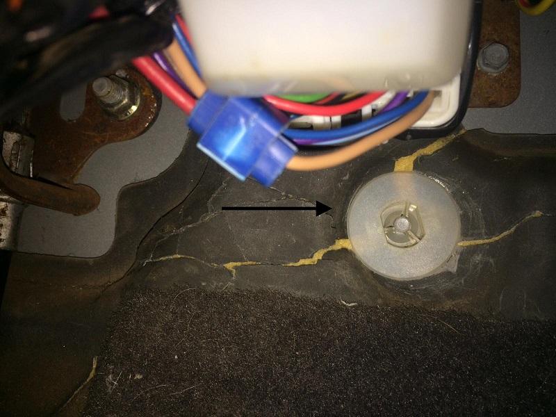
Picture by Leaky88
You will need to remove the trim cover for the left A-post and drop the left sun visor. The red wire with the Cat-5 cable is run up the left side of the dash, A-post, and between the head liner and roof to the center counsel area. The switch can now be attached to the fused red 18awg wire. On the other side of the switch attach another red wire and solder the free end to the orange Cat-5 wires and the monitor’s power wire. Using the 12” piece of black wire, solder the green Cat-5 wires and monitor’s ground wire to it; attach the other end of the wire to the roof brace with a ring terminal and screw. The video monitor signal cable is solder to the Cat-5 blue pair with the shielding soldered to the Cat-5 brown pair. Heat shrink is used to insulate connections. Install the modified overhead center counsel, sun visor, and A-post cover. Using the suction cup mount attach the monitor to the rear view mirror and run the monitor cables into the center counsel through the square hole that was used for the garage door remote and connect to the system cables.
Route the rest of the Cat-5 cable through the left side of the fire wall via the wire grommet, down the left outside fire wall and along the inside of the left frame rail attaching it to the wire harness with zip ties.
Find where the round 4 pin plug would work best for your set up. On my truck it was next to the 7 pin trailer connector in the bed side wall.

4 pin round video connector next to 7 pin trailer connector.
Drill a hole using a 1⅜” hole saw, that is just a little bigger than the 4 pin round connector, check the size of your connector before drilling; run the Cat-5 cable from under the truck bed through the hole. Attach the cable wires to the male 4 pin round connector but DO NOT screw the male plug to the truck until testing is completed. With the Cat-5 cable running alongside the 7 wire trailer cable attach the female side of the 4 pin round connector to the trailer’s Cat-5 cable leaving the cable a few inches longer than the 7 wire trailer cable. Be sure the wires going to the 4 pins of both ends match up color to color.
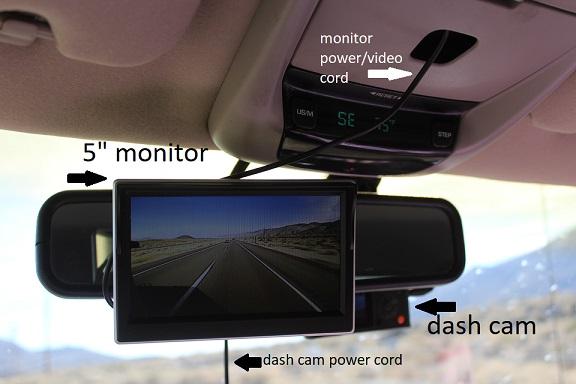
Rear view monitor with forward view dash cam.
Plug the two ends together and turn the power on. The monitor will illuminate and show the view out the back of the trailer but the camera will need to be adjusted horizontal and vertical. Horizontal adjustment is done by loosening the front of the camera by turning its outer cover counterclockwise; this allows the camera to be rotated to get a level view. Vertical adjustment is done by bending the bracket slightly up or down. Two people with radios make this easy. When testing is finished seal the back of the 4 pin connectors with a dab of clear silicon sealer and slide the male connector into the hole and secure with 2 sheet metal screws ¼” x 1”. The exposed Cat-5 cable coming from the trailer can be covered with ¼” split wire loam tubing and secured to the larger trailer cable with zip ties.
If you have a bumper pull trailer a bracket can be made out of sheet metal or angle iron and attached to the trailer hitch.
When the monitor is not being used it is cover with the bag it came in, placed back in its’ box, and store in the center arm rest.
Read through this a few times and have all materials and tools before starting. There are no guaranties implied or expressed.
Written by:
J. Daniel Martin
AKA IBMobile
11/29/2019
-
 1
1