
DESCRIPTION
NOTE: Suspension components with rubber/urethane bushings should be tightened with the vehicle at normal
ride height. It is important to have the springs supporting the weight of the vehicle when the fasteners
are torqued. If springs are not at their normal ride position, vehicle ride comfort could be affected and premature
bushing wear may occur.
Wheel alignment involves the correct positioning of the
wheels in relation to the vehicle. The positioning is
accomplished through suspension and steering linkage
adjustments. An alignment is considered essential
for efficient steering. good directional stability and to
minimize tire wear. The most important measurements
of an alignment are caster, camber and toe.
CAUTION: Never attempt to modify suspension or
steering components by heating or bending.
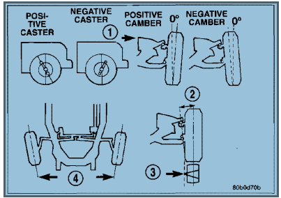
• CASTER is the forward or rearward tilt of the steering knuckle from vertical. Tilting the top of the knuckle
forward provides less positive caster. Tilting the top of the knuckle rearward provides more positive caster.
Positive caster promotes directional stability. This angle enables the front wheels to return to a straight ahead
position after turns
• CAMBER is the inward or outward tilt of the wheel relative to the center of the vehicle. Tilting the top of the
wheel inward provides negative camber. Tilting the top of the wheel outward provides positive camber. Incorrect
camber will cause wear on the inside or outside edge of the tire
• TOE is the difference between the leading inside edges and trailing inside edges of the front tires. Wheel toe
position out of specification cause's unstable steering, uneven tire wear and steering wheel off- center. The
wheel toe position is the final front wheel alignment adjustment
• THRUST ANGLE is the angle of the rear axle relative to the centerline of the vehicle. Incorrect thrust angle
can cause off-center steering and excessive tire wear. This angle is not adjustable, damaged component(s)
must be replaced to correct the thrust angle
DIAGNOSIS AND TESTING
PRE-ALIGNMENT INSPECTION
Before starting wheel alignment, the following inspection and necessary corrections must be completed. Refer to
Suspension and Steering System Diagnosis Chart below for additional information.
1. Inspect tires for size, air pressure and tread wear.
2. Inspect front wheel bearings for wear.
3. Inspect front wheels for excessive radial or lateral runout and balance.
4. Inspect ball studs, linkage pivot points and steering gear for looseness, roughness or binding.
5. Inspect suspension components for wear and noise.
6. Road test the vehicle.
table, th, td { border: 1px solid black; border-collapse: collapse; } th, td { padding: 5px; text-align: left; }
Alighnment
| Condition | Possible Causes | Correction |
| Front End Noise |
1. Loose or worn wheel bearing. 2. Loose or worn steering or suspension components. 3. Loose or worn steering or suspension components. |
1. Replace wheel bearing. 2. Tighten or replace components as necessary. 3. Tighten or replace components as necessary. |
|
EXCESSIVE PLAY IN STEERING |
1. Loose or worn wheel bearing. 2. Loose or worn steering or suspension components. 3. Loose or worn steering gear. |
1. Replace wheel bearing. 2. Tighten or replace components as necessary. 3. Replace steering gear. |
| FRONT WHEELS SHIMMY |
1. Loose or worn wheel bearing. 2. Loose or worn steering or suspension components. 3. Tires worn or out of balance. 4. Alignment |
1. Replace wheel bearing. 2. Tighten or replace components as necessary. 3. Replace or balance tires. 4. Align vehicle to specifications. |
| VEHICLE INSTABILITY |
1. Loose or worn wheel bearing. 2. Loose or worn steering or suspension components. 3. Tire pressure. 4. Alignment |
1. Replace wheel bearing. 2. Tighten or replace components as necessary. 3. Adjust tire pressure. 4. Align vehicle to specifications. |
|
EXCESSIVE STEERING EFFORT |
1. Loose or worn steering gear. 2. Column coupler binding. 3. Tire pressure. 4. Alignment |
1. Replace steering gear. 2. Replace coupler. 3. Adjust tire pressure. 4. Align vehicle to specifications. |
|
VEHICLE PULLS TO ONE SIDE |
1. Tire pressure. 2. Tire 3. Alignment. 4. Loose or worn steering or suspension components. |
1. Adjust tire pressure. 2. Criss-Cross Front lires. 3. Align vehicle to specifications. 4. Tighten or replace components as necessary. |
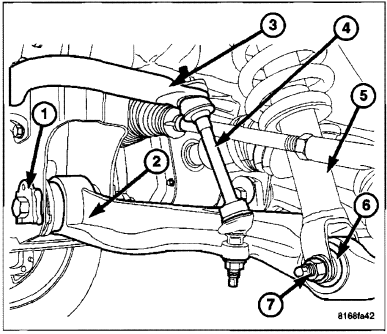
CAMBER AND CASTER ADJUSTMENT
Camber and caster angle adjustments involve changing
the position of the lower control arm (2) in conjunction
with the slotted holes in the frame brackets
(1). Vehicle should be at normal ride height.
TOE ADJUSTMENT
The wheel toe position adjustment is the final adjustment.
1. Start the engine and turn wheels both ways before straightening the wheels. Secure the steering wheel with the
front wheels in the straight-ahead position.
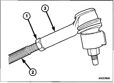
2. Loosen the tie rod jam nuts (1).
NOTE: Each front wheel should be adjusted for
one-half of the total toe position specification.
This will ensure the steering wheel will be centered
when the wheels are positioned straightahead.
3. Adjust the wheel toe position by turning the inner
tie rod (2) as necessary.
4. TIghten the tie rod jam nut (1) to 127 N·m (94 ft.
Ibs.).
5. Verify the specifications
6. Turn off engine.
CAMBER, CASTER AND TOE ADJUSTMENT
Camber and caster angle adjustments involve changing
the position of the lower control arm with the slots
in the frame brackets (1).
CASTER
Moving the front or rear position of the lower control
arm in or out, will change the caster angle and camber
angle significantly. To maintain the camber angle
while adjusting caster, move one pivot bolt of the
lower control arm in or out. Then move the other pivot
bolt of the lower control arm in the opposite direction.
To increase positive caster angle, move the rear position
of the lower control arm inward (toward the
engine). Move the front of the lower control arm outward
(away from the engine) slightly until the desired
camber angle is obtained.
CAMBER
Move both pivot bolts of the lower control arm
together in or out. This will change the camber angle significantly and little effect on the caster angle.
After adjustment is made tighten the lower control arm nuts to proper torque specification.
TOE ADJUSTMENT
The wheel toe position adjustment is the final adjustment.
1. Start the engine and turn wheels both ways before straightening the wheels. Secure the steering wheel with the
front wheels in the straight-ahead position.
2. Loosen the tie rod jam nuts (1).
NOTE: Each front wheel should be adjusted for
one-half of the total toe position specification.
This will ensure the steering wheel will be centered
when the wheels are positioned straightahead.
3. Adjust the wheel toe position by turning the inner
tie rod (2) as necessary.
4. Tighten the tie rod jam nut (1) to 127 N·m (94 ft.
Ibs.).
5. Verify the specifications
6. Turn off engine.
ALIGNMENT LINK/COIL SUSPENSION
Before each alignment reading the vehicle should be
jounced (rear first, then front). Grasp each bumper at
the center and jounce the vehicle up and down several
times. Always release the bumper in the down
position. Set the front end alignment to specifications
while th~ vehicle 'is in its NORMALLY
LOADED CONDITION.
CAMBER: The wheel camber angle is preset and is
not adjustable.
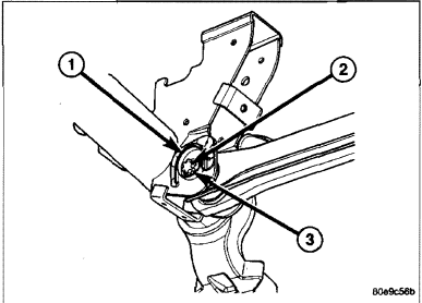
CASTER: Check the caster of the front axle for correct
angle. Be sure the axle is not' bent or twisted.
Road test the vehicle and make left ar'td right turn.
Observe the steering wheel return-to-center position.
Low caster will cause poor steering wheel returnability.
Caster can be adjusted by rotating the cams (3) on
the lower suspension arm.
TOE POSITION: The wheel toe position adjustment should be the final adjustment.
1. Start the engine and turn wheels both ways before straightening the wheels. Center and Secure the steering
wheel and turn off engine.
2. Loosen the adjustment sleeve clamp bolts.
3. Adjust the right wheel toe position with the drag link. Turn the sleeve until the right wheel is at the correct TOE-IN
position. Position clamp bolts to their original position and tighten to specifications. Make sure the toe setting
does not change during clamp tightening.
4. Adjust left wheel toe position with tie rod at teft knuckle. Turn the sleeve untit the left wheel is at the correct
TOE-IN position. Position clamp bolts to their original position and tighten to specifications. Make sure the toe
setting does not change during clamp tightening.
NOTE: Toe setting will change during tightening, Make sure to verify reading after tightening.
5. Verify the right toe setting and a straight steering wheel.
6. Road test the vehicle.
CURB HEIGHT MEASUREMENT (LD)
The wheet alignment is to be checked and all alignment adjustments made with the vehicle at its required curb
height specification.
Vehicle height is to be checked with the vehicle on a flat, level surface, preferably a vehicle alignment rack. The
tires are to be inflated to the recommended pressure. All tires are to be the same size as standard equipment.
Vehicle height is checked with the fuel tank full of fuel, and no passenger or luggage compartment load.
Inspect the vehicle for bent or weak suspension components. Compare the parts tag on the suspect coil spring(s)
to the parts book and the vehicle sales code, checking for a match. Once removed from the vehicle, compare the
coil spring height to a correct new or known good coil spring. The heights should vary if the suspect spring is weak.