Search the Community
Showing results for tags 'abs'.
-
List of Verified and Reliable PCM/ECM Rebuilders
pepsi71ocean posted an Cummins article in Electrical
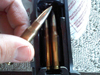
Hey Guys, <<For a List of vendors who have supplied junk parts or didn't stand behind their products....see the bottom of the article.>> pepsi71ocean here. I decided to finally write this article up after another round of people with issues with reman companies. So a while ago back in 10/2015 I shorted out my PCM with a botched rebuild on my Alternator(I forgot to add a sealing washer!) As a result, after replacing the defective alternator I still had no charging on the alternator. I went hunting for a re builder for my PCM. I was quoted almost $800 for a new blank from Dodge, and that didn't include programming. A friend of mine on Facebook who runs a Diesel Rebuild shop in the Midwest forwarded me this company here. <<List of Verified and Reliable PCM/ECM Re-builders>> I have put the company in table format, but If you have another one you used then message me and I'll add the Info. Verified Re-builder Website Telephone Number of Rebuilds Type 1. Autocomputer Specialist https://autocomputerspecialist.com/ 1-954-513-8359 64 PCM-ECM-TIPM 2. Diesel System Services http://www.blacksmokin.com/ 1-619-749-6226 5 ECM 3. Reman Auto Electronics https://www.remanautoelectronics.com/ 1-855-466-6938 2 ECM 4. Crites Car Computers <pending clarification> https://www.critescore.com/ 1-800-900-3267 1 ECM 5. ECM Repair 1 http://www.ecmrepairs.com/ 1-800-737-0915 7 ECM-ABS? 6. SIA Electric http://siaelec.com/ 1-800-737-0915 1 ECM 1. AUTOCOMPUTER SPECIALIST: I was referred to them by my friend Stanley. In the end I believe the price for the rebuild was about $350. I called them, they emailed me the form to fill out with a brief description of the problem, then shipped my PCM to them. And when they opened it up they also sent me a photo and let me know what the issue was. Now they also gave me the list of possible wire issues, but I also knew that I was almost sure it was a botched alternator rebuild that I did on the one NAPA alternator. Here is the photo they sent me below. Total Turn time for me was 5 days and that included the shipping to and from their place in Florida. PCM Rebuil by ACS at 118,506 Miles 11/2015 ACS Repaird a TIPM for a Chrysler200 1/2019 ECM Rebuilt by ACS at 165,406 Miles 10/2021 Current odometer is 201,505 5/10/2023 I also sent out my ECM o be rebuilt in Ocober of 2021, wih 140,000 miles on the truck. I had an another alternator start to go south. To date I know of 4 other Dodge Cummins trucks running rebuild PCM's Although Stanley said he has sent out a dozen PCM/ECM's to them over time for customers from his shop, and that includes some medium duty stuff. UPDATE: 2. Diesel System Services: Referred by mopar1973member Bobalos. Main contact at DSS is Steven Bruce.. He used to work for Cummins. Member has verified ECM still runs. 3. Reman Auto Electronics: Referred by mopar1973member GSP7. Reman Auto Electronics is a subsidiary of Flight Systems Electronics Group. Recommendation by Cummins Fleet Mechanic as well. 4. Crites Car Computers: Referred by mopar1973member Ho$$. Currently I am seeing confirmation that it is not Crites Core Company, Inc. 5. ECM Repair 1: Referred by CumminsForum member indy1k, and 6. SIA Electric: Referred by CumminsForum member chansey NOTES: If you do send me a company, name the number of miles/years you have on your rebuild, and if they were easy to work with or not. If you could a short summary would be good as well. ---------------------------------------------------------------- <<From here below is a list of vendors who have failed to supply good product, or didn't stand behind their product>> Below here is a list of Vendors/re builders that have supplied problematic rebuilds, and have not made attempts to rectify the problem. I didn't have to do much searching online to discover lists of complaints. Re-builder Website Telephone #Complaints FlagShipOne(NY) http://www.fs1inc.com/ 1-516-766-2223 More then one 24 All Computer Resources(FL) https://store.allcomputerresources.com/ 1-866-699-5230 2-1(one guy bought here who didn't have issue) Automotive Scientific Inc. https://www.autoecu.com/ 1-866-983-6688 4 Carcomputer Exchange https://carcomputerexchange.com/ 1-888-875-2958 1 A-1 Cardone http://www.cardone.com/ 1-888-280-8324 12 Auto Computer Exchange https://www.autocomputerexchange.com https://www.autocomputerexchange.net 1-800-680-4275 8 NOTES: All Computer Resources(FL): One member has bought from here with no issue as of 12/16/2018. However they still have one negative review. I hope this list will help people avoid a potential nightmare in dealing with computer issues in the future. UPDATED 05/10/2023 by John Armstrong Jr. Revision 2.2- 10 reviews
-
- 9
-

-

-
- 2nd gen dodge cummin reman ecm
- ecm
- (and 21 more)
-
CCD (Chrysler Collision Detection) Data Bus Description The Chrysler Collision Detection (also referred to as CCD or C2D ) data bus system is a multiplex system used for vehicle communications on many Chrysler Corporation vehicles. Within the context of the CCD system, the term “collision“ refers to the system’s ability to avoid collisions of the electronic data that enters the data bus from various electronic control modules at approximately the same time. Multiplexing is a system that enables the transmission of several messages over a single channel or circuit. Many Chrysler vehicles use this principle for communication between the various microprocessor based electronic control modules. Many of the electronic control modules in a vehicle require information from the same sensing device. In the past, if information from one sensing device was required by several controllers, a wire from each controller needed to be connected in parallel to that sensor. In addition, each controller utilizing analog sensors required an Analog/Digital (A/D) converter in order to “read“ these sensor inputs. Multiplexing reduces wire harness complexity, the sensor current loads, and controller hardware because each sensing device is connected to only one controller, which reads and distributes the sensor information to the other controllers over the data bus. Also, because each controller on the data bus can access the controller sensor inputs to every other controller on the data bus, more function, and feature capabilities are possible. In addition to reducing wire harness complexity, component sensor current loads and controller hardware, multiplexing offers a diagnostic advantage. A multiplex system allows the information flowing between controllers to be monitored using a diagnostic scan tool. The Chrysler system allows an electronic control module to broadcast message data out onto the bus where all other electronic control modules can “hear” the messages that are being sent. When a module hears a message on the data bus that it requires, it relays that message to its microprocessor. Each module ignores the messages on the data bus that are being sent to other electronic control modules. With a diagnostic scan tool connected into the CCD circuit, a technician is able to observe many of the electronic control module function and message outputs while; at the same time, controlling many of the sensor message inputs. The CCD data bus, along with the use of a diagnostic scan tool and a logic based approach to test procedures, as found in the Diagnostic Procedures manuals, allows the trained automotive technician to more easily, accurately and efficiently diagnose the many complex and integrated electronic functions and features found in today’s vehicles. Operation The CCD data bus system was designed to run at a 7812.5 baud rate (or 7812.5 bits per second). In order to successfully transmit and receive binary messages over the CCD data bus, the system requires the following: Bus (+) and Bus (–) Circuits CCD Chips in Each Electronic Control Module Bus Bias and Termination Bus Messaging Bus Message Coding Following are additional details of each of the above system requirements. Bus Circuits The two wires (sometimes referred to as the “twisted pair”) that comprise the CCD data bus are the D1 circuit [Bus (+)], and the D2 circuit [Bus (–)]. The "D" in D1 and D2 identify these as diagnostic circuits. Transmission and receipt of binary messages on the CCD data bus are accomplished by cycling the voltage differential between the Bus (+) and Bus (–) circuits. The two data bus wires are twisted together in order to shield the wires from the effects of any Electro-Magnetic Interference (EMI) from switched voltage sources. An induced EMI voltage can be generated in any wire by a nearby switched voltage or switched ground circuit. By twisting the data bus wires together, the induced voltage spike (either up or down) affects both wires equally. Since both wires are affected equally, a voltage differential still exists between the Bus (+) and Bus (–) circuits, and the data bus messages can still be broadcast or received. The correct specification for data bus wire twisting is one turn for every 44.45 millimeters (1 3⁄4 inches) of wire. CCD Chips In order for an electronic control module to communicate with the CCD data bus, it must have a CCD chip (Fig. 5). The CCD chip contains a differential transmitter/receiver (or transceiver), which is used to send and receive messages. Each module is wired in parallel to the data bus through its CCD chip. The differential transceiver sends messages by using two current drivers: one current source driver, and one current sink driver. The current drivers are matched and allow 0.006 ampere to flow through the data bus circuits. When the transceiver drivers are turned On, the Bus (+) voltage increases slightly, and the Bus (–) voltage decreases slightly. By cycling the drivers On and Off, the CCD chip causes the voltage on the data bus circuit to fluctuate to reflect the message. Once a message is broadcast over the CCD data bus, all electronic control modules on the data bus have the ability to receive it through their CCD chip. Reception of CCD messages is also carried out by the transceiver in the CCD chip. The transceiver monitors the voltage on the data bus for any fluctuations. When data bus voltage fluctuations are detected, they are interpreted by the transceiver as binary messages and sent to the electronic control module’s microprocessor. Bus Bias And Termination The voltage network used by the CCD data bus to transmit messages requires both bias and termination. At least one electronic control module on the data bus must provide a voltage source for the CCD data bus network known as bus bias, and there must be at least one bus termination point for the data bus circuit to be complete. However, while bias and termination are both required for data bus operation, they both do not have to be within the same electronic control module. The CCD data bus is biased to approximately 2.5 volts. With each of the electronic control modules wired in parallel to the data bus, all modules utilize the same bus bias. Therefore, based upon vehicle options, the data bus can accommodate two or twenty electronic control modules without affecting bus voltage. The power supplied to the data bus is known as bus biasing. Bus bias is provided through a series circuit. To properly bias the data bus circuits, a 5 volt supply is provided through a 13 kilohm resistor to the Bus (–) circuit (Fig. 6). Voltage from the Bus (–) circuit flows through a 120 ohm termination resistor to the Bus (+) circuit. The Bus (+) circuit is grounded through another 13 kilohm resistor. While at least one termination resistor is required for the system to operate, most Chrysler systems use two. The second termination resistor serves as a backup (Fig. 7). The termination resistor provides a path for the bus bias voltage. Without a termination point, voltage biasing would not occur. Voltage would go to 5 volts on one bus wire and 0 volts on the other bus wire. The voltage drop through the termination resistor creates 2.51 volts on Bus (–), and 2.49 volts on Bus (+). The voltage difference between the two circuits is 0.02 volts. When the data bus voltage differential is a steady 0.02 volts, the CCD system is considered “idle.” When no input is received from any module and the ignition switch is in the Off position for a pre-programmed length of time, the bus data becomes inactive or enters the ”sleep mode.” Electronic control modules that provide bus bias can be programmed to ”wake up” the data bus and become active upon receiving any predetermined input or when the ignition switch is turned to the On position. Bus Messaging The electronic control modules used in the CCD data bus system contain microprocessors. Digital signals are the means by which microprocessors operate internally and communicate messages to other microprocessors. Digital signals are limited to two states, voltage high or voltage low, corresponding to either a one or a zero. Unlike conventional binary code, the CCD data bus systems translate a small voltage difference as a one (1), and a larger voltage difference as a zero (0). The use of the 0 and 1 is referred to as binary coding. Each binary number is called a bit, and eight bits make up a byte. For example: 01011101 represents a message. The controllers in the multiplex system are able to send thousands of these bytes strung together to communicate a variety of messages. Through the use of binary data transmission, all electronic control modules on the data bus can communicate with each other. The microprocessors in the CCD data bus system translate the binary messages into Hexadecimal Code (or Hex Code). The hex code is the means by which microprocessors communicate and interpret messages. When fault codes are received by the DRBIII scan tool, they are translated into text for display on the DRBIII screen. Although not displayed by the DRBIII for Body Systems, hex codes are shown by the DRBIII for Engine System faults. When the microprocessor signals the transceiver in the CCD chip to broadcast a message, the transceiver turns the current drivers On and Off, which cycles the voltage on the CCD data bus circuits to correspond to the message. At idle, the CCD system recognizes the 0.02 voltage differential as a binary bit 1. When the current drivers are actuated, the voltage differential from idle must increase by 0.02 volt for the CCD system to recognize a binary bit 0. The nominal voltage differential for a 0 bit is 0.100 volts. However, data bus voltage differentials can range anywhere between 0.02 and 0.120 volts. Bus Failure The CCD data bus can be monitored using the DRBIII scan tool. However, it is possible for the data bus to pass all tests since the voltage parameters will be in “range“ and false signals are being sent. There are essentially 12 “hard failures“ that can occur with the CCD data bus: Bus Shorted to Battery Bus Shorted to 5 Volts Bus Shorted to Ground Bus (+) Shorted to Bus (–) Bus (–) and Bus (+) Open Bus (+) Open Bus (–) Open No Bus Bias Bus Bias Level Too High Bus Bias Level Too Low No Bus Termination Not Receiving Bus Messages Correctly Refer to the appropriate diagnostic procedures for details on how to diagnose these faults using a DRBIII scan tool. Bus Failure Visual Symptoms & Diagnosis The following visible symptoms or customer complaints, alone or in combination, may indicate a CCD data bus failure: Airbag Indicator Lamp and Malfunction Indicator Lamp (MIL) Illuminated Instrument Cluster Gauges (All) Inoperative No Compass Mini-Trip Computer (CMTC) Operation Wiring Diagrams
- 2 reviews
-
- 3
-
-
-
- ccd bus
- ccd data bus
- (and 5 more)
-
Replacing Later Model ABS Speed Sensors I would like to make a shout out to the member that sent me the front sensor back in the spring of the year. Long overdue but now I got the time to replace my well wore out and damaged ABS sensors. So here we go I'm going to do both side. Total time to replace is 30 minutes for both. Start out by jacking up the front axle and jack standing the axle for safety. Now remove the tire using the proper socket and impact gun. Mine being aftermarket wheels is a 3/4" socket. After the wheel is removed grab a large flat blade screwdriver and pry both caliper piston back a little. Now using a 5/8" 12 point socket remove the two bolts holding the caliper frame. Now lift off the caliper and frame as a assembly. Now you should be able to remove the rotor. Note: Early series trucks have the rotors held in place by the wheel studs which requires removal of the unit bearing. Now grab a proper sized Allen wrench to remove the Allen bolt holding the speed sensor. Now you may lightly bend the shield metal up to gain some room. Now I'm working with the passenger side so I got to get the BHAF and heat shield out of the way. Now I will have access to the connector up top. So now just careful remove all the old ABS sensor and lead taking note of where its routed along the brake line and frame. Now route the new sensor in the very same manner. Making sure to snap in the wire in all the clips and push the holders back into the holes on the frame. Now carefully bend the shield metal back down over the ABS speed sensor. Slide your rotor back up on the wheel studs. If you need to use a pair of open face lug nuts to hold the rotor in place. Now slip the caliper and frame back over the rotor. Grab your blue loc-tite and put a bit on the bolts. Re-install the two bolts holding the caliper frame. Before mounting your wheel again double check that the wire is out of the way of any moving parts and not going to be damaged. Now remount your wheel and tire and torque your lug nuts. Now for the lights ABS and BRAKE both lights should go out within a very short amount of travel. Like in my case just getting outside the door frame of the shop the ABS and BRAKE lights went out.
-

ABS System Diagnostics / Troubleshooting
Mopar1973Man posted an Cummins article in Axles, Suspension & Brakes
ABS System Diagnostics / Troubleshooting 4 Wheel Anti-Lock Brake System 4 Wheel Anti-Lock Braking System Wiring Diagrams 4 wheel abs system.pdf I find it's really common to hear people complain about ABS and BRAKE lights being lit. There are a few simple things you can do to diagnose your problem. Check your ABS fuses under the hood fuse #11 and check the #3 fuse inside the cab (driver side door jamb). Replace any that are blown. Step on you brake pedal and see if the tail lights light up and turn off when released. If not, repair the brake light switch. Shift the transfer case into 4WD and check if the 4WD light comes on. (4WD equipped vehicles). If not repair the 4WD switch. Does the speedometer work? If so, the rear speed sensor in the differential is functional. So now that you done that much that means that it one of the front speed sensors that has either become disconnected or the sensor has failed. If the lights remain the only way I know to diagnose this correctly is at a Dodge dealer. They have the tools to hook up to the ABS computer and pull the error codes and tell you what has failed. Once you've repaired the problem you must drive the vehicle to reset the ABS and BRAKE lights. Also, take the second and check the error codes on the ECM/PCM and reset any error codes. Description - CAB (Controller Antilock Brakes) The CAB (Controller Antilock Brakes) monitors wheel speed sensor inputs continuously while the vehicle is in motion. However, the CAB (Controller Antilock Brakes) will not activate any ABS components as long as sensor inputs indicate normal braking. During normal braking, the master cylinder, power booster and wheel brake units all function as they would in a vehicle without ABS. The HCU components are not activated. The purpose of the antilock system is to prevent wheel lockup during periods of high wheel slip. Preventing lockup helps maintain vehicle braking action and steering control. The antilock CAB (Controller Antilock Brakes) activates the system whenever sensor signals indicate periods of wheel slip. Periods of wheel slip occur when brake stops involve high pedal pressure and rate of vehicle deceleration. The antilock system prevents lockup during a wheel slip condition by modulating fluid apply pressure to the wheel brake units. Brake fluid applies pressure is modulated according to wheel speed, a degree of slip and rate of deceleration. Sensors at each front wheel convert wheel speed into electrical signals. These signals are transmitted to the CAB (Controller Antilock Brakes) for processing and determination of wheel slip and deceleration rate. The ABS system has three fluid pressure control channels. The front brakes are controlled separately and the rear brakes in tandem. A speed sensor input signal indicating a wheel slip condition activates the CAB (Controller Antilock Brakes) antilock program. There are Two solenoid valves (Isolation and Dump valve) which are used in each antilock control channel. The valves are all located within the HCU valve body and work in pairs to either increase, hold, or decrease apply pressure as needed in the individual control channels. During an ABS stop, the ISO valve actuates, Stopping any more pressure buildup to the calipers. Then the Dump valve dumps off pressure until the wheel unlocks. This will continue until the wheels quit slipping altogether. Operation - System Self-Test Battery voltage is supplied to the CAB (Controller Antilock Brakes) when a speed of 15 miles per hour is reached. The CAB (Controller Antilock Brakes) performs a system initialization procedure at this point. Initialization consists of a static and dynamic self-check of system electrical components. The static and dynamic checks occur at ignition start up. During the dynamic check, the CAB (Controller Antilock Brakes) briefly cycles the pump and solenoids to verify operation. An audible noise may be heard during this self-check. This noise should be considered normal. If an ABS component exhibits a fault during initialization, the CAB (Controller Antilock Brakes) illuminates the amber warning light and registers a fault code in the microprocessor memory. Mopar's Note: OBDII Testing / DRBIII Testing As for testing equipment the ODBII code reader will only see P0500 error code but the DRBIII tool that Dodge dealer has been capable of seeing all speed sensors and test the ABS braking system for it faults. A lot of people ask me how much a DRBIII tool cost... They are approximate $6,000.00 for a DRBIII tool. So it might be worth a trip to the dealer and have them diagnose the system for you. Speed Sensor Operation The Wheel Speed Sensor consists of a magnet surrounded by windings from a single strand of wire. The sensor sends a small AC signal to the CAB (Controller Antilock Brakes). This signal is generated by magnetic induction. The magnetic induction is created when a toothed sensor ring (exciter ring or tone wheel) passes the stationary magnetic WSS. When the ring gear is rotated, the exciter ring passes the tip of the WSS. As the exciter ring tooth approaches the tip of the WSS, the magnetic lines of force expand, causing the magnetic field to cut across the sensor's windings. This, in turn, causes current to flow through the WSS circuit in one direction. When the exciter ring tooth moves away from the sensor tip, the magnetic lines of force collapse cutting the winding in the opposite direction. This causes the current to flow in the opposite direction. Every time a tooth of the exciter ring passes the tip of the WSS, an AC signal is generated. Each AC signal (positive to negative signal or sine wave) is interpreted by the CAB (Controller Antilock Brakes). It then compares the frequency of the sinewave to a time value to calculate vehicle speed. The CAB (Controller Antilock Brakes) continues to monitor the frequency to determine a deceleration rate that would indicate a possible wheel-locking tendency. The signal strength of any magnetic induction sensor is directly affected by: Magnetic field strength; the stronger the magnetic field, the stronger the signal Number of windings in the sensor; more windings provide a stronger signal Exciter ring speed; the faster the exciter ring/tone wheel rotates, the stronger the signal will be Distance between the exciter ring teeth and WSS; the closer the WSS is to the exciter ring/tone wheel, the stronger the signal will be The rear WSS is not adjustable. A clearance specification has been established for manufacturing tolerances. If the clearance is not within these specifications, then either the WSS or other components may be damaged. The clearance between the WSS and the exciter ring is 0.005 - 0.050 in. Resetting the ABS / BRAKE light You must repair/replace the damaged sensor/unit of the ABS braking system then drive the vehicle a short distance at road speeds before the lights will go off. The ABS module does an on the fly diagnostic of all the system and if all sensor is reporting properly the system will automatically reset at a speed of 15 MPH. WARNING! Do not disconnect the batteries to try to reset the ABS/BRAKE lights. All this does is wipe out the APPS sensor calibration in the ECM. But it will not reset ABS error code. CAB (Controller Antilock Brakes) Inputs The CAB (Controller Antilock Brakes) continuously monitors the speed of the differential ring gear by monitoring signals generated by the rear wheel speed sensor. The CAB determines a wheel locking tendency when it recognizes the ring gear is decelerating too rapidly. The CAB (Controller Antilock Brakes) monitors the following inputs to determine when a wheel locking tendency may exist: Rear Wheel Speed Sensor Brake Lamp Switch Brake Warning Lamp Switch Reset Switch 4WD Switch (If equipped) CAB (Controller Antilock Brakes) Outputs The CAB (Controller Antilock Brakes) controls the following outputs for anti-lock braking and brake warning information: RWAL Valve ABS Warning Lamp Brake Warning Lamp Mopar's Notes: P0500 Error Code - Explained Since 4 wheel anti-lock brakes rely on 2 front axle sensors and 1 rear wheel sensor. The CAB (Controller Antilock Brakes) is watching the speed output from all 3 sensors at one time. So when on a slick surface like ice, gravel, wet pavement, etc. when you accelerate rapidly and cause the rear tires to spin the rear speed sensor jumps up in speed rapidly and the front 2 sensors could be at zero speed yet. So the CAB (Controller Antilock Brakes) can't understand how the rear half of the truck is doing say 35 MPH and the front half is doing 0 MPH. POOF! P0500 code is thrown. -
CCD (Chrysler Collision Detection) Data Bus Description The Chrysler Collision Detection (also referred to as CCD or C2D ) data bus system is a multiplex system used for vehicle communications on many Chrysler Corporation vehicles. Within the context of the CCD system, the term “collision“ refers to the system’s ability to avoid collisions of the electronic data that enters the data bus from various electronic control modules at approximately the same time. Multiplexing is a system that enables the transmission of several messages over a single channel or circuit. Many Chrysler vehicles use this principle for communication between the various microprocessor based electronic control modules. Many of the electronic control modules in a vehicle require information from the same sensing device. In the past, if information from one sensing device was required by several controllers, a wire from each controller needed to be connected in parallel to that sensor. In addition, each controller utilizing analog sensors required an Analog/Digital (A/D) converter in order to “read“ these sensor inputs. Multiplexing reduces wire harness complexity, the sensor current loads, and controller hardware because each sensing device is connected to only one controller, which reads and distributes the sensor information to the other controllers over the data bus. Also, because each controller on the data bus can access the controller sensor inputs to every other controller on the data bus, more function, and feature capabilities are possible. In addition to reducing wire harness complexity, component sensor current loads and controller hardware, multiplexing offers a diagnostic advantage. A multiplex system allows the information flowing between controllers to be monitored using a diagnostic scan tool. The Chrysler system allows an electronic control module to broadcast message data out onto the bus where all other electronic control modules can “hear” the messages that are being sent. When a module hears a message on the data bus that it requires, it relays that message to its microprocessor. Each module ignores the messages on the data bus that are being sent to other electronic control modules. With a diagnostic scan tool connected into the CCD circuit, a technician is able to observe many of the electronic control module function and message outputs while; at the same time, controlling many of the sensor message inputs. The CCD data bus, along with the use of a diagnostic scan tool and a logic based approach to test procedures, as found in the Diagnostic Procedures manuals, allows the trained automotive technician to more easily, accurately and efficiently diagnose the many complex and integrated electronic functions and features found in today’s vehicles. Operation The CCD data bus system was designed to run at a 7812.5 baud rate (or 7812.5 bits per second). In order to successfully transmit and receive binary messages over the CCD data bus, the system requires the following: Bus (+) and Bus (–) Circuits CCD Chips in Each Electronic Control Module Bus Bias and Termination Bus Messaging Bus Message Coding Following are additional details of each of the above system requirements. Bus Circuits The two wires (sometimes referred to as the “twisted pair”) that comprise the CCD data bus are the D1 circuit [Bus (+)], and the D2 circuit [Bus (–)]. The "D" in D1 and D2 identify these as diagnostic circuits. Transmission and receipt of binary messages on the CCD data bus are accomplished by cycling the voltage differential between the Bus (+) and Bus (–) circuits. The two data bus wires are twisted together in order to shield the wires from the effects of any Electro-Magnetic Interference (EMI) from switched voltage sources. An induced EMI voltage can be generated in any wire by a nearby switched voltage or switched ground circuit. By twisting the data bus wires together, the induced voltage spike (either up or down) affects both wires equally. Since both wires are affected equally, a voltage differential still exists between the Bus (+) and Bus (–) circuits, and the data bus messages can still be broadcast or received. The correct specification for data bus wire twisting is one turn for every 44.45 millimeters (1 3⁄4 inches) of wire. CCD Chips In order for an electronic control module to communicate with the CCD data bus, it must have a CCD chip (Fig. 5). The CCD chip contains a differential transmitter/receiver (or transceiver), which is used to send and receive messages. Each module is wired in parallel to the data bus through its CCD chip. The differential transceiver sends messages by using two current drivers: one current source driver, and one current sink driver. The current drivers are matched and allow 0.006 ampere to flow through the data bus circuits. When the transceiver drivers are turned On, the Bus (+) voltage increases slightly, and the Bus (–) voltage decreases slightly. By cycling the drivers On and Off, the CCD chip causes the voltage on the data bus circuit to fluctuate to reflect the message. Once a message is broadcast over the CCD data bus, all electronic control modules on the data bus have the ability to receive it through their CCD chip. Reception of CCD messages is also carried out by the transceiver in the CCD chip. The transceiver monitors the voltage on the data bus for any fluctuations. When data bus voltage fluctuations are detected, they are interpreted by the transceiver as binary messages and sent to the electronic control module’s microprocessor. Bus Bias And Termination The voltage network used by the CCD data bus to transmit messages requires both bias and termination. At least one electronic control module on the data bus must provide a voltage source for the CCD data bus network known as bus bias, and there must be at least one bus termination point for the data bus circuit to be complete. However, while bias and termination are both required for data bus operation, they both do not have to be within the same electronic control module. The CCD data bus is biased to approximately 2.5 volts. With each of the electronic control modules wired in parallel to the data bus, all modules utilize the same bus bias. Therefore, based upon vehicle options, the data bus can accommodate two or twenty electronic control modules without affecting bus voltage. The power supplied to the data bus is known as bus biasing. Bus bias is provided through a series circuit. To properly bias the data bus circuits, a 5 volt supply is provided through a 13 kilohm resistor to the Bus (–) circuit (Fig. 6). Voltage from the Bus (–) circuit flows through a 120 ohm termination resistor to the Bus (+) circuit. The Bus (+) circuit is grounded through another 13 kilohm resistor. While at least one termination resistor is required for the system to operate, most Chrysler systems use two. The second termination resistor serves as a backup (Fig. 7). The termination resistor provides a path for the bus bias voltage. Without a termination point, voltage biasing would not occur. Voltage would go to 5 volts on one bus wire and 0 volts on the other bus wire. The voltage drop through the termination resistor creates 2.51 volts on Bus (–), and 2.49 volts on Bus (+). The voltage difference between the two circuits is 0.02 volts. When the data bus voltage differential is a steady 0.02 volts, the CCD system is considered “idle.” When no input is received from any module and the ignition switch is in the Off position for a pre-programmed length of time, the bus data becomes inactive or enters the ”sleep mode.” Electronic control modules that provide bus bias can be programmed to ”wake up” the data bus and become active upon receiving any predetermined input or when the ignition switch is turned to the On position. Bus Messaging The electronic control modules used in the CCD data bus system contain microprocessors. Digital signals are the means by which microprocessors operate internally and communicate messages to other microprocessors. Digital signals are limited to two states, voltage high or voltage low, corresponding to either a one or a zero. Unlike conventional binary code, the CCD data bus systems translate a small voltage difference as a one (1), and a larger voltage difference as a zero (0). The use of the 0 and 1 is referred to as binary coding. Each binary number is called a bit, and eight bits make up a byte. For example: 01011101 represents a message. The controllers in the multiplex system are able to send thousands of these bytes strung together to communicate a variety of messages. Through the use of binary data transmission, all electronic control modules on the data bus can communicate with each other. The microprocessors in the CCD data bus system translate the binary messages into Hexadecimal Code (or Hex Code). The hex code is the means by which microprocessors communicate and interpret messages. When fault codes are received by the DRBIII scan tool, they are translated into text for display on the DRBIII screen. Although not displayed by the DRBIII for Body Systems, hex codes are shown by the DRBIII for Engine System faults. When the microprocessor signals the transceiver in the CCD chip to broadcast a message, the transceiver turns the current drivers On and Off, which cycles the voltage on the CCD data bus circuits to correspond to the message. At idle, the CCD system recognizes the 0.02 voltage differential as a binary bit 1. When the current drivers are actuated, the voltage differential from idle must increase by 0.02 volt for the CCD system to recognize a binary bit 0. The nominal voltage differential for a 0 bit is 0.100 volts. However, data bus voltage differentials can range anywhere between 0.02 and 0.120 volts. Bus Failure The CCD data bus can be monitored using the DRBIII scan tool. However, it is possible for the data bus to pass all tests since the voltage parameters will be in “range“ and false signals are being sent. There are essentially 12 “hard failures“ that can occur with the CCD data bus: Bus Shorted to Battery Bus Shorted to 5 Volts Bus Shorted to Ground Bus (+) Shorted to Bus (–) Bus (–) and Bus (+) Open Bus (+) Open Bus (–) Open No Bus Bias Bus Bias Level Too High Bus Bias Level Too Low No Bus Termination Not Receiving Bus Messages Correctly Refer to the appropriate diagnostic procedures for details on how to diagnose these faults using a DRBIII scan tool. Bus Failure Visual Symptoms & Diagnosis The following visible symptoms or customer complaints, alone or in combination, may indicate a CCD data bus failure: Airbag Indicator Lamp and Malfunction Indicator Lamp (MIL) Illuminated Instrument Cluster Gauges (All) Inoperative No Compass Mini-Trip Computer (CMTC) Operation Wiring Diagrams View full Cummins article
-
Hey Guys, <<For a List of vendors who have supplied junk parts or didn't stand behind their products....see the bottom of the article.>> pepsi71ocean here. I decided to finally write this article up after another round of people with issues with reman companies. So a while ago back in 10/2015 I shorted out my PCM with a botched rebuild on my Alternator(I forgot to add a sealing washer!) As a result, after replacing the defective alternator I still had no charging on the alternator. I went hunting for a re builder for my PCM. I was quoted almost $800 for a new blank from Dodge, and that didn't include programming. A friend of mine on Facebook who runs a Diesel Rebuild shop in the Midwest forwarded me this company here. <<List of Verified and Reliable PCM/ECM Re-builders>> I have put the company in table format, but If you have another one you used then message me and I'll add the Info. Verified Re-builder Website Telephone Number of Rebuilds Type 1. Autocomputer Specialist https://autocomputerspecialist.com/ 1-954-513-8359 64 PCM-ECM-TIPM 2. Diesel System Services http://www.blacksmokin.com/ 1-619-749-6226 5 ECM 3. Reman Auto Electronics https://www.remanautoelectronics.com/ 1-855-466-6938 2 ECM 4. Crites Car Computers <pending clarification> https://www.critescore.com/ 1-800-900-3267 1 ECM 5. ECM Repair 1 http://www.ecmrepairs.com/ 1-800-737-0915 7 ECM-ABS? 6. SIA Electric http://siaelec.com/ 1-800-737-0915 1 ECM 1. AUTOCOMPUTER SPECIALIST: I was referred to them by my friend Stanley. In the end I believe the price for the rebuild was about $350. I called them, they emailed me the form to fill out with a brief description of the problem, then shipped my PCM to them. And when they opened it up they also sent me a photo and let me know what the issue was. Now they also gave me the list of possible wire issues, but I also knew that I was almost sure it was a botched alternator rebuild that I did on the one NAPA alternator. Here is the photo they sent me below. Total Turn time for me was 5 days and that included the shipping to and from their place in Florida. PCM Rebuil by ACS at 118,506 Miles 11/2015 ACS Repaird a TIPM for a Chrysler200 1/2019 ECM Rebuilt by ACS at 165,406 Miles 10/2021 Current odometer is 201,505 5/10/2023 I also sent out my ECM o be rebuilt in Ocober of 2021, wih 140,000 miles on the truck. I had an another alternator start to go south. To date I know of 4 other Dodge Cummins trucks running rebuild PCM's Although Stanley said he has sent out a dozen PCM/ECM's to them over time for customers from his shop, and that includes some medium duty stuff. UPDATE: 2. Diesel System Services: Referred by mopar1973member Bobalos. Main contact at DSS is Steven Bruce.. He used to work for Cummins. Member has verified ECM still runs. 3. Reman Auto Electronics: Referred by mopar1973member GSP7. Reman Auto Electronics is a subsidiary of Flight Systems Electronics Group. Recommendation by Cummins Fleet Mechanic as well. 4. Crites Car Computers: Referred by mopar1973member Ho$$. Currently I am seeing confirmation that it is not Crites Core Company, Inc. 5. ECM Repair 1: Referred by CumminsForum member indy1k, and 6. SIA Electric: Referred by CumminsForum member chansey NOTES: If you do send me a company, name the number of miles/years you have on your rebuild, and if they were easy to work with or not. If you could a short summary would be good as well. ---------------------------------------------------------------- <<From here below is a list of vendors who have failed to supply good product, or didn't stand behind their product>> Below here is a list of Vendors/re builders that have supplied problematic rebuilds, and have not made attempts to rectify the problem. I didn't have to do much searching online to discover lists of complaints. Re-builder Website Telephone #Complaints FlagShipOne(NY) http://www.fs1inc.com/ 1-516-766-2223 More then one 24 All Computer Resources(FL) https://store.allcomputerresources.com/ 1-866-699-5230 2-1(one guy bought here who didn't have issue) Automotive Scientific Inc. https://www.autoecu.com/ 1-866-983-6688 4 Carcomputer Exchange https://carcomputerexchange.com/ 1-888-875-2958 1 A-1 Cardone http://www.cardone.com/ 1-888-280-8324 12 Auto Computer Exchange https://www.autocomputerexchange.com https://www.autocomputerexchange.net 1-800-680-4275 8 NOTES: All Computer Resources(FL): One member has bought from here with no issue as of 12/16/2018. However they still have one negative review. I hope this list will help people avoid a potential nightmare in dealing with computer issues in the future. UPDATED 05/10/2023 by John Armstrong Jr. Revision 2.2 View full Cummins article
-
All I seem to be having the common problem of my ABS and Brake light on my dash being on, so I am following the document below, and it seems that my 4WD light does not come on when I shift into 4WD (been like this for a while though), so I replaced the switch last night. The truck will still go into 4WD with front tires pulling, but the light still does not come on. I did test the switch and the 4WD light will come on when I have the wire harness connected and I use my fingers to hold the switch down, but not when the switch is mounted in the axle. With this being said is this a different issue and I still may have a bad ABS sensor? Any insight on further troubleshooting tips would be greatly appreciated. Note I do not think it is the rear ABS sensor since my speed sensor is working.
-
 I know, old topic. It's just that no one seems to be in the same situation I am. I just finished replacing front rotors, calipers, and pads (Powerstop Z36 kit) and discovered the passenger side hub was shot, spun like a fidget spinner. Also replaced the driver side axle shaft assembly since the threads got screwed up taking the nut off. Anyway, I also threw a new ABS sensor on the driver side hub from a brand new bearing my friend messed up and gave to me, since I had access to it. I get everything back together, bleed the brakes, and as soon as I cross the 20-25 mph mark, the ABS/Brake Christmas tree lights up. Does not come on with brake pedal action, comes on when I hit that speed range and then doesn't go off until I turn the truck off. Pedal feels mushy compared to before, but I think that's an unrelated bleeding issue. Of course 2 minutes into the bed-in procedure and Bambi wants to say hi, knocked my front license plate off but that was it (lights came on before running over deer btw). Not sure what would be causing this, I read the other threads and I doubt that it's a tone ring issue since one hub is new (Timken) and the other was just fine beforehand. Front ABS doesn't do much of anything (Don't feel anything in the pedal either), but it didn't do much before the job either. I forgot to disconnect the batteries when changing the sensors, but disconnecting them later did not change anything. Also, the parking brake light works as designed before I hit 20-25 mph and it stays on, so I doubt it's anything with that system specifically. 4wd light does not come on unless I put it on 4wd, so nothing unusual there. The only area I touched was the front hub/brake assembly, so that must be where some change is causing an error, just not sure what. Any help is appreciated, thanks.
 -
Well seems I am the latest victim of the ABS and brake light coming on.Came on sometime yesterday while driving around. I checked for codes with my Scan Gauge and nothing. Rechecked and nothing. I used the key trick and got P0500, which made sense to me. The SG still does not see it so it wont clear it. Guess i will check the connector and then replace it if all seems well with the wires. Still surprised the SG does not see it.
-
 Ok guys I need some input. I just got my abs module back from Module Masters and put it in the truck and what do you know, no abs light, motor isn't continuously running, Yes! So stinking happy. Drive about two miles, getting off the freeway and look down and see the abs and brake light on. Crap. So I get out of the truck,open the hood... The motor is running. So module Masters says they will take of it, they didn't hassle me whatsoever, which is nice. But my question, could something be going through my electrical system and causing that relay or whatever it is to fail? I'm guna order a fluke ( either 114 or 115, not sure what would be better) and test the alternator for ac noise. But can it be another issue? Two years of the abs light staring at me, I want it gone for good.
 -
Hey everyone, New member here but long time reader, I recently bought another dually (lucky number 3) to replace my 2000 24v. Sorry in advance for the long post, just want to give all info Amazing truck and very well built, however.... i bought it and the abs module was unplugged, never really considered this a problem ( not a fan of abs) but im sure you all know that the speedodoesnt work without it and is a requirement for certification in Ontario. So i plugg the moduleback in, everything is fine...until it isnt, the truck began to stutter at various rpm (changed ECT Sensor) once i did that the "Stutter" was only in 6th gear at 2100rpm (had a comp box and a CAT 95gph LP at the time) Unplug the Module and everything is right as rain and has excellent power. Decided to switch over to a fass (in case of contamination) and also switched to the Juice w/Attitude ( just a personal preference... i love the dummy settings because im a dummy) Changed the MAP at this point because i had no electronic reading for boost. Plugged back in at this point and test drove it for about 5 minutes before the issue came back. I am stumped on this one gentlemen, I sure hope someone has encountered this issue before. Thank you in advanced. Chad Pressure @ VP >16psi....Boost Max 47psi...EGT never exceed 1200F* 2002 Dodge Ram 3500 Sport (Daily/Plow Truck) -Edge Juice w/attitude (unlocked plus EGT on manifold) -BD Super B Special -BD SS Manifold -BD Intake Horn -Hamilton 100lb Valve Spring -Hamilton Pushrods -ARP 625 Headstuds -Southbend 3250 Clutch -Hewitt Mechanical Gauges (Fuel,EGT{After turbo},Fuel Pressure) -Fass 150 gph LP -Colt Cam (Big Stick) Stage 3 -VP44 (100+ aftermarket)

-
ABS Failure - Diagnostics Tips 4 Wheel Anti-Lock Brake System 2 Wheel Anti-Lock Brake System (RWAL - Rear Wheel Anti-Lock) I find its really common to hear people complain about ABS and BRAKE lights being lit. There is a few simple things you can do to diagnose your problem. [*] Check your ABS fuses under the hood fuse #11 and check the #3 fuse inside the cab (driver side door jamb). Replace any that are blown. [*]Step on you brake pedal and see if the tail lights light up and turn off when released. If not repair the brake light switch. [*]Shift the transfer case into 4WD and check if the 4WD light comes on. (4WD equipped vehicles). If not repair the 4WD switch. [*]Does the speedometer work? If so the rear speed sensor in the differential is functional. So now that you done that much that means that it one of the front speed sensors that has either become disconnected or the sensor has failed. If the lights remain the only way I know to diagnose this correctly is at a Dodge dealer. They have the tools to hook up to the ABS computer and pull the error codes and tell you what has failed. Once you've repaired the problem you must drive the vehicle to reset the ABS and BRAKE lights. Also take the second and check the error codes on the ECM/PCM and reset any error codes. Description - CAB (Controller Antilock Brakes) The Controller Antilock Brakes (CAB) is a microprocessor which handles testing, monitoring and controllingthe ABS brake system operation (Fig. 10). The CAB functions are: [*] Perform self-test diagnostics. [*]Monitor the RWAL brake system for proper operation. [*]Control the RWAL valve solenoids. NOTE: If the CAB needs to be replaced, the rear axle type and tire revolutions per mile must be programed into the new CAB. For axle type refer to Group 3 Differential and Driveline. For tire revolutions per mile,(Refer to 22 - TIRES/WHEELS/TIRES - SPECIFICATIONS) . To program the CAB refer to the Chassis Diagnostic Manual. Operation - System Self-Test When the ignition switch is turned-on the microprocessor RAM and ROM are tested. If an error occurs during the test, a DTC will be set into the RAM memory. However it is possible the DTC will not be stored in memory if the error has occurred in the RAM module were the DTC’s are stored. Also it is possible a DTC may not be stored if the error has occurred in the ROM which signals the RAM to store the DTC. CAB Inputs The CAB continuously monitors the speed of the differential ring gear by monitoring signals generated by the rear wheel speed sensor. The CAB determines a wheel locking tendency when it recognizes the ring gear is decelerating too rapidly. The CAB monitors the following inputs to determine when a wheel locking tendency may exists: [*] Rear Wheel Speed Sensor [*]Brake Lamp Switch [*]Brake Warning Lamp Switch [*]Reset Switch [*]4WD Switch (If equipped) CAB Outputs The CAB controls the following outputs for antilock braking and brake warning information: [*] RWAL Valve [*]ABS Warning Lamp [*]Brake Warning Lamp P0500 Error Code - Explained Since 4 wheel antilock brakes rely on 2 front axle sensors and 1 rear wheel sensor. The CAB is watching the speed output from all 3 sensors at one time. So when on a slick surface like ice, gravel, wet pavement, etc. when you accelerate rapidly and cause the rear tires to spin the rear speed sensor jumps up in speed rapidly and the front 2 sensor could be at zero speed yet. So the CAB can't understand how the rear half of the truck is doing say 35 MPH and the front half is doing 0 MPH. POOF! P0500 code is thrown.
-
 I just bought a 99 3500 i have a problem i have no steering and the abs motor pump is staying on. i had to diconnect the abs pump to stop running. i put fluid in the powers steering pump and worked the wheel back and forth then i looked under the truck for the leaks but not leaks on power steering pump. and still no power steering. and the abs pump stays on
 -
Ok so the other day i took my 01 2500 apart to install new ball joints. I took the brake lines off the calipers to give myself more room to work and when i went to reinstall everything went smoothly. I bled the lines i have full pressure coming from all 4 calipers. I cannot get any foot pressure. I tryed a "new/used" Hydroboost and it was not the problem. I am out of ideas and cannot get the pedal to hold pressure. I start it and try to move it doesnt grab till the very bottom and not to much. ` :confused: I think there could be air trapped in the abs sensor? I have no idea any help would be great. Thanks in Advance!!!!!!!
-
So I replaced my wheel bearing/hub assembly yesterday, I didn't put the heat shield/dust shield plate back on due to destroying it getting the hub off. My ABS wire was then able to rub on my rotor, not to my knowledge of course, and proceeded to cut the cable almost in half. Is there any way to fix the cable? I really don't want to buy another 270 dollar hub for a dagum cable.
-
Hey guys i am new around here and have some questions! The 4x4 will not engage on my truck. i understand the vacuum operated system and suspect that this is where to start on fixing it. however, my ABS and parking brake light are always on as well. is there anyway that the two could be connected? when i put the truck into 4H there is no change in the steering and the lights do not illuminate. in 4L still no lights or steering change but it does go into low range. any help you could offer on this would be great! also if anyone has experience trouble shooting the vacuum system or has a diagram i would appreciate the insight! thanks in advance guys.Also not sure how to do a sig but here is the info:2001 2500 5.9 SO w/5 spd. new VP44 and FRRP w/ big-line kit from DAP. everything else is stock
-
Hi there guys. A couple days ago I was driving down the highway and the ABS and brake light came on. Wasn't sure if it was anything big so I pulled over and shut truck off, restarted and lights were off. I asked someone and they said it was common and no big deal. Now, last night both came on, won't go off and now my speedometer wasnt working at low speeds in town but then when I would get to 45mph or so it would jump up and when I would slow down, it would drop to zero again. Is this an issue with the batteries or something bigger or are they separate problems? I have the 99 and no code reader so just trying to figure it out! I did have brakes changed about a month ago and the mechanic said my drivers side battery was weak. I plan on replacing both batteries this morning and hopefully that will help! The batteries are from 07 so it's probably time anyways. Thanks for your help guys!
-
my abs and brake light has been on since i bought the truck and after doing some reading i figured that it might be the rear sensor, so when I was at autozone ( or the twilight zone depends on who's working) I picked up a rear speed sensor. Then, i heard if the speedo is working (mine was), probably not the rear so i didn't install it figuring maybe i'll stop by my friend shop and use the snapon scanner that can read abs codes when I get a chance. Today I put the back axle up on some stands and pointed it away from the house and ran it in 6th gear, because i'am trying to isolate a 60-70mph heavy vibration and guest what no speedo. So, with the truck already in the air and the sensor on the front seat I gave it a shot. No light! Back to diagnosing the vibration.
-
i just got a P 0500 1693 I have no clue.
-
On my way to school today I got a pending DTC. I stopped to check it out and got P0500 and p1693. Cleared it and then my ABS light came on. I looked up in my ultragauge to see if i had any other codes and got a P0216. Sounds like p0216 can pop as a result of others coming about. p0500 says theres no vehicle speed signal but I was getting a MPH reading on both my dash and the ultragauge as I was driving. None of this makes any sense... Damn truck! --- Update to the previous post... Parking brake light also stays on. --- Update to the previous post... This all sounds familiar, 1genro had this issue
-
My speedo still works so am guessing the rear sensor is still good, not a fuse prob., so I am going to take the sensors off the front of my ,wrecked 2000 3500 with auto, parts truck for me, and try them on my truck. Does anyone fore see a problem? Thanks
-
My lights are on and it pulses like a bad rotor.Can anyone tell me what to check.I had all this problem before i replaced the wheelbearings,rotors and ball-u-joints.When i am light on them around 30mph it seems ok, hit them hard the pedal pulses.I only have a smarty to check codes so i cant get into the abs computer.
-
2001 dodge cummins 4x4 auto trans . do i have 4 wheel abs?
-
 I was running down the road last Wednesday and i Look down and the abs and brake lights were on. So i pulled codes today. 250 251 230 500 501 1689 1693 1765 I could see 1 code but all of these? Any ideas guys? thanks in advance.
 -
A 2004 when you first crank up the ABS light comes on and the alarm will ding, then it will go out after maybe 20 seconds. Anybody have any ideas what it may be? Thanks for any help.