Search the Community
Showing results for tags 'pcm'.
Found 20 results
-
List of Verified and Reliable PCM/ECM Rebuilders
pepsi71ocean posted an Cummins article in Electrical
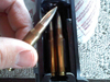
Hey Guys, <<For a List of vendors who have supplied junk parts or didn't stand behind their products....see the bottom of the article.>> pepsi71ocean here. I decided to finally write this article up after another round of people with issues with reman companies. So a while ago back in 10/2015 I shorted out my PCM with a botched rebuild on my Alternator(I forgot to add a sealing washer!) As a result, after replacing the defective alternator I still had no charging on the alternator. I went hunting for a re builder for my PCM. I was quoted almost $800 for a new blank from Dodge, and that didn't include programming. A friend of mine on Facebook who runs a Diesel Rebuild shop in the Midwest forwarded me this company here. <<List of Verified and Reliable PCM/ECM Re-builders>> I have put the company in table format, but If you have another one you used then message me and I'll add the Info. Verified Re-builder Website Telephone Number of Rebuilds Type 1. Autocomputer Specialist https://autocomputerspecialist.com/ 1-954-513-8359 64 PCM-ECM-TIPM 2. Diesel System Services http://www.blacksmokin.com/ 1-619-749-6226 5 ECM 3. Reman Auto Electronics https://www.remanautoelectronics.com/ 1-855-466-6938 2 ECM 4. Crites Car Computers <pending clarification> https://www.critescore.com/ 1-800-900-3267 1 ECM 5. ECM Repair 1 http://www.ecmrepairs.com/ 1-800-737-0915 7 ECM-ABS? 6. SIA Electric http://siaelec.com/ 1-800-737-0915 1 ECM 1. AUTOCOMPUTER SPECIALIST: I was referred to them by my friend Stanley. In the end I believe the price for the rebuild was about $350. I called them, they emailed me the form to fill out with a brief description of the problem, then shipped my PCM to them. And when they opened it up they also sent me a photo and let me know what the issue was. Now they also gave me the list of possible wire issues, but I also knew that I was almost sure it was a botched alternator rebuild that I did on the one NAPA alternator. Here is the photo they sent me below. Total Turn time for me was 5 days and that included the shipping to and from their place in Florida. PCM Rebuil by ACS at 118,506 Miles 11/2015 ACS Repaird a TIPM for a Chrysler200 1/2019 ECM Rebuilt by ACS at 165,406 Miles 10/2021 Current odometer is 201,505 5/10/2023 I also sent out my ECM o be rebuilt in Ocober of 2021, wih 140,000 miles on the truck. I had an another alternator start to go south. To date I know of 4 other Dodge Cummins trucks running rebuild PCM's Although Stanley said he has sent out a dozen PCM/ECM's to them over time for customers from his shop, and that includes some medium duty stuff. UPDATE: 2. Diesel System Services: Referred by mopar1973member Bobalos. Main contact at DSS is Steven Bruce.. He used to work for Cummins. Member has verified ECM still runs. 3. Reman Auto Electronics: Referred by mopar1973member GSP7. Reman Auto Electronics is a subsidiary of Flight Systems Electronics Group. Recommendation by Cummins Fleet Mechanic as well. 4. Crites Car Computers: Referred by mopar1973member Ho$$. Currently I am seeing confirmation that it is not Crites Core Company, Inc. 5. ECM Repair 1: Referred by CumminsForum member indy1k, and 6. SIA Electric: Referred by CumminsForum member chansey NOTES: If you do send me a company, name the number of miles/years you have on your rebuild, and if they were easy to work with or not. If you could a short summary would be good as well. ---------------------------------------------------------------- <<From here below is a list of vendors who have failed to supply good product, or didn't stand behind their product>> Below here is a list of Vendors/re builders that have supplied problematic rebuilds, and have not made attempts to rectify the problem. I didn't have to do much searching online to discover lists of complaints. Re-builder Website Telephone #Complaints FlagShipOne(NY) http://www.fs1inc.com/ 1-516-766-2223 More then one 24 All Computer Resources(FL) https://store.allcomputerresources.com/ 1-866-699-5230 2-1(one guy bought here who didn't have issue) Automotive Scientific Inc. https://www.autoecu.com/ 1-866-983-6688 4 Carcomputer Exchange https://carcomputerexchange.com/ 1-888-875-2958 1 A-1 Cardone http://www.cardone.com/ 1-888-280-8324 12 Auto Computer Exchange https://www.autocomputerexchange.com https://www.autocomputerexchange.net 1-800-680-4275 8 NOTES: All Computer Resources(FL): One member has bought from here with no issue as of 12/16/2018. However they still have one negative review. I hope this list will help people avoid a potential nightmare in dealing with computer issues in the future. UPDATED 05/10/2023 by John Armstrong Jr. Revision 2.2- 10 reviews
-
- 9
-

-

-
- 2nd gen dodge cummin reman ecm
- ecm
- (and 21 more)
-
CCD (Chrysler Collision Detection) Data Bus Description The Chrysler Collision Detection (also referred to as CCD or C2D ) data bus system is a multiplex system used for vehicle communications on many Chrysler Corporation vehicles. Within the context of the CCD system, the term “collision“ refers to the system’s ability to avoid collisions of the electronic data that enters the data bus from various electronic control modules at approximately the same time. Multiplexing is a system that enables the transmission of several messages over a single channel or circuit. Many Chrysler vehicles use this principle for communication between the various microprocessor based electronic control modules. Many of the electronic control modules in a vehicle require information from the same sensing device. In the past, if information from one sensing device was required by several controllers, a wire from each controller needed to be connected in parallel to that sensor. In addition, each controller utilizing analog sensors required an Analog/Digital (A/D) converter in order to “read“ these sensor inputs. Multiplexing reduces wire harness complexity, the sensor current loads, and controller hardware because each sensing device is connected to only one controller, which reads and distributes the sensor information to the other controllers over the data bus. Also, because each controller on the data bus can access the controller sensor inputs to every other controller on the data bus, more function, and feature capabilities are possible. In addition to reducing wire harness complexity, component sensor current loads and controller hardware, multiplexing offers a diagnostic advantage. A multiplex system allows the information flowing between controllers to be monitored using a diagnostic scan tool. The Chrysler system allows an electronic control module to broadcast message data out onto the bus where all other electronic control modules can “hear” the messages that are being sent. When a module hears a message on the data bus that it requires, it relays that message to its microprocessor. Each module ignores the messages on the data bus that are being sent to other electronic control modules. With a diagnostic scan tool connected into the CCD circuit, a technician is able to observe many of the electronic control module function and message outputs while; at the same time, controlling many of the sensor message inputs. The CCD data bus, along with the use of a diagnostic scan tool and a logic based approach to test procedures, as found in the Diagnostic Procedures manuals, allows the trained automotive technician to more easily, accurately and efficiently diagnose the many complex and integrated electronic functions and features found in today’s vehicles. Operation The CCD data bus system was designed to run at a 7812.5 baud rate (or 7812.5 bits per second). In order to successfully transmit and receive binary messages over the CCD data bus, the system requires the following: Bus (+) and Bus (–) Circuits CCD Chips in Each Electronic Control Module Bus Bias and Termination Bus Messaging Bus Message Coding Following are additional details of each of the above system requirements. Bus Circuits The two wires (sometimes referred to as the “twisted pair”) that comprise the CCD data bus are the D1 circuit [Bus (+)], and the D2 circuit [Bus (–)]. The "D" in D1 and D2 identify these as diagnostic circuits. Transmission and receipt of binary messages on the CCD data bus are accomplished by cycling the voltage differential between the Bus (+) and Bus (–) circuits. The two data bus wires are twisted together in order to shield the wires from the effects of any Electro-Magnetic Interference (EMI) from switched voltage sources. An induced EMI voltage can be generated in any wire by a nearby switched voltage or switched ground circuit. By twisting the data bus wires together, the induced voltage spike (either up or down) affects both wires equally. Since both wires are affected equally, a voltage differential still exists between the Bus (+) and Bus (–) circuits, and the data bus messages can still be broadcast or received. The correct specification for data bus wire twisting is one turn for every 44.45 millimeters (1 3⁄4 inches) of wire. CCD Chips In order for an electronic control module to communicate with the CCD data bus, it must have a CCD chip (Fig. 5). The CCD chip contains a differential transmitter/receiver (or transceiver), which is used to send and receive messages. Each module is wired in parallel to the data bus through its CCD chip. The differential transceiver sends messages by using two current drivers: one current source driver, and one current sink driver. The current drivers are matched and allow 0.006 ampere to flow through the data bus circuits. When the transceiver drivers are turned On, the Bus (+) voltage increases slightly, and the Bus (–) voltage decreases slightly. By cycling the drivers On and Off, the CCD chip causes the voltage on the data bus circuit to fluctuate to reflect the message. Once a message is broadcast over the CCD data bus, all electronic control modules on the data bus have the ability to receive it through their CCD chip. Reception of CCD messages is also carried out by the transceiver in the CCD chip. The transceiver monitors the voltage on the data bus for any fluctuations. When data bus voltage fluctuations are detected, they are interpreted by the transceiver as binary messages and sent to the electronic control module’s microprocessor. Bus Bias And Termination The voltage network used by the CCD data bus to transmit messages requires both bias and termination. At least one electronic control module on the data bus must provide a voltage source for the CCD data bus network known as bus bias, and there must be at least one bus termination point for the data bus circuit to be complete. However, while bias and termination are both required for data bus operation, they both do not have to be within the same electronic control module. The CCD data bus is biased to approximately 2.5 volts. With each of the electronic control modules wired in parallel to the data bus, all modules utilize the same bus bias. Therefore, based upon vehicle options, the data bus can accommodate two or twenty electronic control modules without affecting bus voltage. The power supplied to the data bus is known as bus biasing. Bus bias is provided through a series circuit. To properly bias the data bus circuits, a 5 volt supply is provided through a 13 kilohm resistor to the Bus (–) circuit (Fig. 6). Voltage from the Bus (–) circuit flows through a 120 ohm termination resistor to the Bus (+) circuit. The Bus (+) circuit is grounded through another 13 kilohm resistor. While at least one termination resistor is required for the system to operate, most Chrysler systems use two. The second termination resistor serves as a backup (Fig. 7). The termination resistor provides a path for the bus bias voltage. Without a termination point, voltage biasing would not occur. Voltage would go to 5 volts on one bus wire and 0 volts on the other bus wire. The voltage drop through the termination resistor creates 2.51 volts on Bus (–), and 2.49 volts on Bus (+). The voltage difference between the two circuits is 0.02 volts. When the data bus voltage differential is a steady 0.02 volts, the CCD system is considered “idle.” When no input is received from any module and the ignition switch is in the Off position for a pre-programmed length of time, the bus data becomes inactive or enters the ”sleep mode.” Electronic control modules that provide bus bias can be programmed to ”wake up” the data bus and become active upon receiving any predetermined input or when the ignition switch is turned to the On position. Bus Messaging The electronic control modules used in the CCD data bus system contain microprocessors. Digital signals are the means by which microprocessors operate internally and communicate messages to other microprocessors. Digital signals are limited to two states, voltage high or voltage low, corresponding to either a one or a zero. Unlike conventional binary code, the CCD data bus systems translate a small voltage difference as a one (1), and a larger voltage difference as a zero (0). The use of the 0 and 1 is referred to as binary coding. Each binary number is called a bit, and eight bits make up a byte. For example: 01011101 represents a message. The controllers in the multiplex system are able to send thousands of these bytes strung together to communicate a variety of messages. Through the use of binary data transmission, all electronic control modules on the data bus can communicate with each other. The microprocessors in the CCD data bus system translate the binary messages into Hexadecimal Code (or Hex Code). The hex code is the means by which microprocessors communicate and interpret messages. When fault codes are received by the DRBIII scan tool, they are translated into text for display on the DRBIII screen. Although not displayed by the DRBIII for Body Systems, hex codes are shown by the DRBIII for Engine System faults. When the microprocessor signals the transceiver in the CCD chip to broadcast a message, the transceiver turns the current drivers On and Off, which cycles the voltage on the CCD data bus circuits to correspond to the message. At idle, the CCD system recognizes the 0.02 voltage differential as a binary bit 1. When the current drivers are actuated, the voltage differential from idle must increase by 0.02 volt for the CCD system to recognize a binary bit 0. The nominal voltage differential for a 0 bit is 0.100 volts. However, data bus voltage differentials can range anywhere between 0.02 and 0.120 volts. Bus Failure The CCD data bus can be monitored using the DRBIII scan tool. However, it is possible for the data bus to pass all tests since the voltage parameters will be in “range“ and false signals are being sent. There are essentially 12 “hard failures“ that can occur with the CCD data bus: Bus Shorted to Battery Bus Shorted to 5 Volts Bus Shorted to Ground Bus (+) Shorted to Bus (–) Bus (–) and Bus (+) Open Bus (+) Open Bus (–) Open No Bus Bias Bus Bias Level Too High Bus Bias Level Too Low No Bus Termination Not Receiving Bus Messages Correctly Refer to the appropriate diagnostic procedures for details on how to diagnose these faults using a DRBIII scan tool. Bus Failure Visual Symptoms & Diagnosis The following visible symptoms or customer complaints, alone or in combination, may indicate a CCD data bus failure: Airbag Indicator Lamp and Malfunction Indicator Lamp (MIL) Illuminated Instrument Cluster Gauges (All) Inoperative No Compass Mini-Trip Computer (CMTC) Operation Wiring Diagrams
- 2 reviews
-
- 3
-
-
-
- ccd bus
- ccd data bus
- (and 5 more)
-
 CCD (Chrysler Collision Detection) Data Bus Description The Chrysler Collision Detection (also referred to as CCD or C2D ) data bus system is a multiplex system used for vehicle communications on many Chrysler Corporation vehicles. Within the context of the CCD system, the term “collision“ refers to the system’s ability to avoid collisions of the electronic data that enters the data bus from various electronic control modules at approximately the same time. Multiplexing is a system that enables the transmission of several messages over a single channel or circuit. Many Chrysler vehicles use this principle for communication between the various microprocessor based electronic control modules. Many of the electronic control modules in a vehicle require information from the same sensing device. In the past, if information from one sensing device was required by several controllers, a wire from each controller needed to be connected in parallel to that sensor. In addition, each controller utilizing analog sensors required an Analog/Digital (A/D) converter in order to “read“ these sensor inputs. Multiplexing reduces wire harness complexity, the sensor current loads, and controller hardware because each sensing device is connected to only one controller, which reads and distributes the sensor information to the other controllers over the data bus. Also, because each controller on the data bus can access the controller sensor inputs to every other controller on the data bus, more function, and feature capabilities are possible. In addition to reducing wire harness complexity, component sensor current loads and controller hardware, multiplexing offers a diagnostic advantage. A multiplex system allows the information flowing between controllers to be monitored using a diagnostic scan tool. The Chrysler system allows an electronic control module to broadcast message data out onto the bus where all other electronic control modules can “hear” the messages that are being sent. When a module hears a message on the data bus that it requires, it relays that message to its microprocessor. Each module ignores the messages on the data bus that are being sent to other electronic control modules. With a diagnostic scan tool connected into the CCD circuit, a technician is able to observe many of the electronic control module function and message outputs while; at the same time, controlling many of the sensor message inputs. The CCD data bus, along with the use of a diagnostic scan tool and a logic based approach to test procedures, as found in the Diagnostic Procedures manuals, allows the trained automotive technician to more easily, accurately and efficiently diagnose the many complex and integrated electronic functions and features found in today’s vehicles. Operation The CCD data bus system was designed to run at a 7812.5 baud rate (or 7812.5 bits per second). In order to successfully transmit and receive binary messages over the CCD data bus, the system requires the following: Bus (+) and Bus (–) Circuits CCD Chips in Each Electronic Control Module Bus Bias and Termination Bus Messaging Bus Message Coding Following are additional details of each of the above system requirements. Bus Circuits The two wires (sometimes referred to as the “twisted pair”) that comprise the CCD data bus are the D1 circuit [Bus (+)], and the D2 circuit [Bus (–)]. The "D" in D1 and D2 identify these as diagnostic circuits. Transmission and receipt of binary messages on the CCD data bus are accomplished by cycling the voltage differential between the Bus (+) and Bus (–) circuits. The two data bus wires are twisted together in order to shield the wires from the effects of any Electro-Magnetic Interference (EMI) from switched voltage sources. An induced EMI voltage can be generated in any wire by a nearby switched voltage or switched ground circuit. By twisting the data bus wires together, the induced voltage spike (either up or down) affects both wires equally. Since both wires are affected equally, a voltage differential still exists between the Bus (+) and Bus (–) circuits, and the data bus messages can still be broadcast or received. The correct specification for data bus wire twisting is one turn for every 44.45 millimeters (1 3⁄4 inches) of wire. CCD Chips In order for an electronic control module to communicate with the CCD data bus, it must have a CCD chip (Fig. 5). The CCD chip contains a differential transmitter/receiver (or transceiver), which is used to send and receive messages. Each module is wired in parallel to the data bus through its CCD chip. The differential transceiver sends messages by using two current drivers: one current source driver, and one current sink driver. The current drivers are matched and allow 0.006 ampere to flow through the data bus circuits. When the transceiver drivers are turned On, the Bus (+) voltage increases slightly, and the Bus (–) voltage decreases slightly. By cycling the drivers On and Off, the CCD chip causes the voltage on the data bus circuit to fluctuate to reflect the message. Once a message is broadcast over the CCD data bus, all electronic control modules on the data bus have the ability to receive it through their CCD chip. Reception of CCD messages is also carried out by the transceiver in the CCD chip. The transceiver monitors the voltage on the data bus for any fluctuations. When data bus voltage fluctuations are detected, they are interpreted by the transceiver as binary messages and sent to the electronic control module’s microprocessor. Bus Bias And Termination The voltage network used by the CCD data bus to transmit messages requires both bias and termination. At least one electronic control module on the data bus must provide a voltage source for the CCD data bus network known as bus bias, and there must be at least one bus termination point for the data bus circuit to be complete. However, while bias and termination are both required for data bus operation, they both do not have to be within the same electronic control module. The CCD data bus is biased to approximately 2.5 volts. With each of the electronic control modules wired in parallel to the data bus, all modules utilize the same bus bias. Therefore, based upon vehicle options, the data bus can accommodate two or twenty electronic control modules without affecting bus voltage. The power supplied to the data bus is known as bus biasing. Bus bias is provided through a series circuit. To properly bias the data bus circuits, a 5 volt supply is provided through a 13 kilohm resistor to the Bus (–) circuit (Fig. 6). Voltage from the Bus (–) circuit flows through a 120 ohm termination resistor to the Bus (+) circuit. The Bus (+) circuit is grounded through another 13 kilohm resistor. While at least one termination resistor is required for the system to operate, most Chrysler systems use two. The second termination resistor serves as a backup (Fig. 7). The termination resistor provides a path for the bus bias voltage. Without a termination point, voltage biasing would not occur. Voltage would go to 5 volts on one bus wire and 0 volts on the other bus wire. The voltage drop through the termination resistor creates 2.51 volts on Bus (–), and 2.49 volts on Bus (+). The voltage difference between the two circuits is 0.02 volts. When the data bus voltage differential is a steady 0.02 volts, the CCD system is considered “idle.” When no input is received from any module and the ignition switch is in the Off position for a pre-programmed length of time, the bus data becomes inactive or enters the ”sleep mode.” Electronic control modules that provide bus bias can be programmed to ”wake up” the data bus and become active upon receiving any predetermined input or when the ignition switch is turned to the On position. Bus Messaging The electronic control modules used in the CCD data bus system contain microprocessors. Digital signals are the means by which microprocessors operate internally and communicate messages to other microprocessors. Digital signals are limited to two states, voltage high or voltage low, corresponding to either a one or a zero. Unlike conventional binary code, the CCD data bus systems translate a small voltage difference as a one (1), and a larger voltage difference as a zero (0). The use of the 0 and 1 is referred to as binary coding. Each binary number is called a bit, and eight bits make up a byte. For example: 01011101 represents a message. The controllers in the multiplex system are able to send thousands of these bytes strung together to communicate a variety of messages. Through the use of binary data transmission, all electronic control modules on the data bus can communicate with each other. The microprocessors in the CCD data bus system translate the binary messages into Hexadecimal Code (or Hex Code). The hex code is the means by which microprocessors communicate and interpret messages. When fault codes are received by the DRBIII scan tool, they are translated into text for display on the DRBIII screen. Although not displayed by the DRBIII for Body Systems, hex codes are shown by the DRBIII for Engine System faults. When the microprocessor signals the transceiver in the CCD chip to broadcast a message, the transceiver turns the current drivers On and Off, which cycles the voltage on the CCD data bus circuits to correspond to the message. At idle, the CCD system recognizes the 0.02 voltage differential as a binary bit 1. When the current drivers are actuated, the voltage differential from idle must increase by 0.02 volt for the CCD system to recognize a binary bit 0. The nominal voltage differential for a 0 bit is 0.100 volts. However, data bus voltage differentials can range anywhere between 0.02 and 0.120 volts. Bus Failure The CCD data bus can be monitored using the DRBIII scan tool. However, it is possible for the data bus to pass all tests since the voltage parameters will be in “range“ and false signals are being sent. There are essentially 12 “hard failures“ that can occur with the CCD data bus: Bus Shorted to Battery Bus Shorted to 5 Volts Bus Shorted to Ground Bus (+) Shorted to Bus (–) Bus (–) and Bus (+) Open Bus (+) Open Bus (–) Open No Bus Bias Bus Bias Level Too High Bus Bias Level Too Low No Bus Termination Not Receiving Bus Messages Correctly Refer to the appropriate diagnostic procedures for details on how to diagnose these faults using a DRBIII scan tool. Bus Failure Visual Symptoms & Diagnosis The following visible symptoms or customer complaints, alone or in combination, may indicate a CCD data bus failure: Airbag Indicator Lamp and Malfunction Indicator Lamp (MIL) Illuminated Instrument Cluster Gauges (All) Inoperative No Compass Mini-Trip Computer (CMTC) Operation Wiring Diagrams View full Cummins article
 -
I'm currently searching through google and the forum for help. Posting because I'm confused as to whether its my PCM or ECM also clueless. Last night I was driving and I parked and shut off my truck. I did switch my tune to one I got from here but used previously without any problems. A few minutes later I started my truck just fine as always and about a second later it shut off. ODO flashes "no bus" / no wait to start light / overhead says "ccd" / gauges don't work / airdog won't turn on , cranks strong but gets NO fuel at ALL / connected scan tool but says it can't connect / also phone seems like phone can't connect to quad adrenaline some extra info about my truck-- 150hp inj / 650 trans / head studs /
-
Hey everyone! I'm looking for any help I can get. We just acquired a 98 dodge ram 1500 sport, 5.2L 4wd auto trans. The guy we got it from is not mechanically inclined, and told us that it "just died" on him one day, and has been sitting in his driveway ever since. Upon looking into it ourselves, we came to find that there is no fuel pump sound and no spark going to the plugs or the coil. The truck is trying to start fine, but will not turn over. We replaced the crankshaft position sensor and tried a new ignition coil as well. Obviously, none of that worked. Also checked all the fuses and relays, including the ASD relay. We even tried wire brushing the mounting bolts for the PCM, as they are apparently the ground for it, and that did not work either. We are now thinking it might be the PCM itself, and are looking into getting one from a junked dodge. I know that the P/N on the PCM (56046343AD) needs to match to be compatible. Does anyone have any other ideas or experiences similar to this? We are desperate. (Also, I've heard that without turning the key on, the PCM can lock itself when removed... is this true? And if so, how would you go about getting one out of a junked vehicle safely...?) Thank you in advance for any help. -Jess Sorry, I also meant to add that the gauges are sitting at zero, the odometer has been flashing on and off, and there is no CE light but we tried connecting 2 different OBD2 readers and one said "No Link" and other said "Error."
-
 Hey guys, so my truck will go into o/d when the temps are cool. I’m refraining from saying “cold” because it doesn’t ever get cold where I am. Relative to most of the world. Haha once my trans temp gets up around 100 deg F my pcm doesn’t send the ground signal to engage o/d. It will hold as long as I’m in it, but once disengaged it will not re engage as long as trans temps are above 100 deg. I checked the resistance that the temp sensor is sending to the pcm and it is accurate, as long as the key is off or the pcm is unplugged. As soon as I plug it in or turn the key on I lose about 400ohms resistance. Idk why. Plz help. I got a reman pcm from Chrysler and it’s not very old. I’ve tried running a resistor in-line the sendor wire but idk if I didn it right because it didn’t yield good results. plz help. This truck has been a tough fighter. Haha
 -
 Here's my tale of woe. '99 3500 5.9 Cummins A/T--Started out with the the torque converter lock/unlock issue, found the cure purely by accident (pulled the alternator charge line which was lying directly on the alternator away from the alternator, and problem went away for a couple weeks until the line returned to its original position--ah ha!!!). Traced the charge line, and ended up basically doing the W-T Ground Mod, things ran perfectly for about 4 years. I could not believe that crazy ground splice on the port side of the motor--engineer must have been hitting the sauce on that one. Wish I'd found this site back then!!! Forgot to mention, I bought the truck used in 2015 with only 46,000 original miles on it--when I had the tranny rebuilt at 90,000, the tranny guy told me there were some non-OEM parts in the tranny--in other words, someone had been in there trying to fix the torque converter issue thinking it was a transmission problem. This has been a source of great amusement to me, as the original owner sold this great truck because it had an "unfixable" transmission problem (and of course didn't tell me)--so thanks, MM1973, for letting people know about this easy fix even though I had to find it by accident! While on a trip out of Alaska, got a no-charge condition and ended up doing an external regulator fix to get home. Never liked the external regulator, as frequently the voltage would run high (15+). After reading MM1973's article on the fuse, decided to implement it and restore wiring to original condition (with the addition of the 5A fuse)--purchased a used PCM, sent it off to be programmed to my VIN, installed it when it returned. Lo and behold, the voltage was in the low 14s and the vehicle ran great with the exception of Brake and ABS lights (turned out the VIN programming did not take; the ABS module did not like an incorrect VIN!) and an occasional "surge" in RPM. Meanwhile, I sent the original PCM in for repair. A friend rode with me and monitored system voltage on his scanner--there was a very slight "spike" of 0.1V every time the "surge" occurred (could only see it on the graph). Strangely enough, the PCM rebuilder reported there were no problems with the original PCM (I asked them to replace that circuit regardless, which they did, and then tested for heat and vibration). When I received it back and installed it, all was well with the exception of the tranny surge--it seemed to be bad one day, and disappear the next. It was not throwing any codes, at least that my Edge reported. About 2 weeks later, while driving to work (temp was about minus 30), the surge got pretty nasty so I locked out the overdrive to smooth things out. Just before I pulled into work, I pushed the overdrive switch--it didn't shift, and my voltage dropped to 11.9. As I suspected, the 5A fuse had blown. I replaced it with a 7.5A, but still had no charging. I'm guessing the original PCM has acted up again. So I put my backup PCM in and went for a test drive. Voltage was good, and she shifted into overdrive. Problem solved, or so I thought. I turned around to head back to the shop, and got on it a little to ensure things were working properly. Instantly the voltage dropped to 11, and no overdrive. Edge pulled down a P1765, P1682 and P0753. Put the ohmmeter to the dark blue line coming off pin C3 25 to the alternator, have good continuity and no continuity to ground (same with green wire from C2 10). Going to have transmission solenoids and wiring harness replaced this weekend based on transmission guy's previous experience with similar issues. Based on the wiring diagram, it seems it has to be a transmission circuit issue. But I'm still totally baffled as to the origin of the no charge situation--either the PCM rebuilder doesn't know what he's talking about or I've got some real gremlins running around in my truck (he said it tested good, and it worked well for a couple of weeks, but now this--and after I put in the protective fuse). And full disclosure--I'm totally dumb when it comes to understanding automatic transmissions and 12V systems, but I did sleep in a Holiday Inn Express once. Sorry to be so long winded! I'd like to hear other members' ideas on this. I'll report back after the solenoid/harness replacement this weekend. Thanks in advance!
- 16 replies
-
- 1
-
-
- pcm
- alternator
- (and 4 more)
-
Hey Guys, <<For a List of vendors who have supplied junk parts or didn't stand behind their products....see the bottom of the article.>> pepsi71ocean here. I decided to finally write this article up after another round of people with issues with reman companies. So a while ago back in 10/2015 I shorted out my PCM with a botched rebuild on my Alternator(I forgot to add a sealing washer!) As a result, after replacing the defective alternator I still had no charging on the alternator. I went hunting for a re builder for my PCM. I was quoted almost $800 for a new blank from Dodge, and that didn't include programming. A friend of mine on Facebook who runs a Diesel Rebuild shop in the Midwest forwarded me this company here. <<List of Verified and Reliable PCM/ECM Re-builders>> I have put the company in table format, but If you have another one you used then message me and I'll add the Info. Verified Re-builder Website Telephone Number of Rebuilds Type 1. Autocomputer Specialist https://autocomputerspecialist.com/ 1-954-513-8359 64 PCM-ECM-TIPM 2. Diesel System Services http://www.blacksmokin.com/ 1-619-749-6226 5 ECM 3. Reman Auto Electronics https://www.remanautoelectronics.com/ 1-855-466-6938 2 ECM 4. Crites Car Computers <pending clarification> https://www.critescore.com/ 1-800-900-3267 1 ECM 5. ECM Repair 1 http://www.ecmrepairs.com/ 1-800-737-0915 7 ECM-ABS? 6. SIA Electric http://siaelec.com/ 1-800-737-0915 1 ECM 1. AUTOCOMPUTER SPECIALIST: I was referred to them by my friend Stanley. In the end I believe the price for the rebuild was about $350. I called them, they emailed me the form to fill out with a brief description of the problem, then shipped my PCM to them. And when they opened it up they also sent me a photo and let me know what the issue was. Now they also gave me the list of possible wire issues, but I also knew that I was almost sure it was a botched alternator rebuild that I did on the one NAPA alternator. Here is the photo they sent me below. Total Turn time for me was 5 days and that included the shipping to and from their place in Florida. PCM Rebuil by ACS at 118,506 Miles 11/2015 ACS Repaird a TIPM for a Chrysler200 1/2019 ECM Rebuilt by ACS at 165,406 Miles 10/2021 Current odometer is 201,505 5/10/2023 I also sent out my ECM o be rebuilt in Ocober of 2021, wih 140,000 miles on the truck. I had an another alternator start to go south. To date I know of 4 other Dodge Cummins trucks running rebuild PCM's Although Stanley said he has sent out a dozen PCM/ECM's to them over time for customers from his shop, and that includes some medium duty stuff. UPDATE: 2. Diesel System Services: Referred by mopar1973member Bobalos. Main contact at DSS is Steven Bruce.. He used to work for Cummins. Member has verified ECM still runs. 3. Reman Auto Electronics: Referred by mopar1973member GSP7. Reman Auto Electronics is a subsidiary of Flight Systems Electronics Group. Recommendation by Cummins Fleet Mechanic as well. 4. Crites Car Computers: Referred by mopar1973member Ho$$. Currently I am seeing confirmation that it is not Crites Core Company, Inc. 5. ECM Repair 1: Referred by CumminsForum member indy1k, and 6. SIA Electric: Referred by CumminsForum member chansey NOTES: If you do send me a company, name the number of miles/years you have on your rebuild, and if they were easy to work with or not. If you could a short summary would be good as well. ---------------------------------------------------------------- <<From here below is a list of vendors who have failed to supply good product, or didn't stand behind their product>> Below here is a list of Vendors/re builders that have supplied problematic rebuilds, and have not made attempts to rectify the problem. I didn't have to do much searching online to discover lists of complaints. Re-builder Website Telephone #Complaints FlagShipOne(NY) http://www.fs1inc.com/ 1-516-766-2223 More then one 24 All Computer Resources(FL) https://store.allcomputerresources.com/ 1-866-699-5230 2-1(one guy bought here who didn't have issue) Automotive Scientific Inc. https://www.autoecu.com/ 1-866-983-6688 4 Carcomputer Exchange https://carcomputerexchange.com/ 1-888-875-2958 1 A-1 Cardone http://www.cardone.com/ 1-888-280-8324 12 Auto Computer Exchange https://www.autocomputerexchange.com https://www.autocomputerexchange.net 1-800-680-4275 8 NOTES: All Computer Resources(FL): One member has bought from here with no issue as of 12/16/2018. However they still have one negative review. I hope this list will help people avoid a potential nightmare in dealing with computer issues in the future. UPDATED 05/10/2023 by John Armstrong Jr. Revision 2.2 View full Cummins article
-
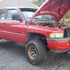
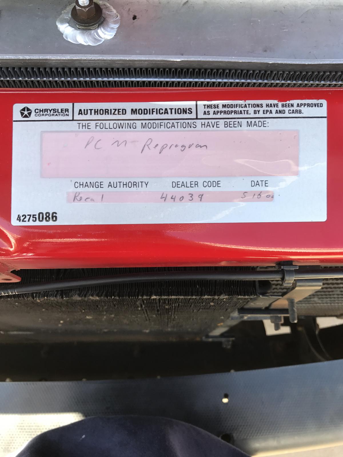
Idea's on what this was for? Curious if a local dealer could lookup my VIN and find out what was done. I'm currently searching the TSB's on http://dodgeram.info/ Number on the bottom left is the Mopar part number for the label itself. This is a California truck.

-
My cruise control light was always staying on, but the fly-by-wire cruise didn't work. After much problem solving, I finally took the 2001.5 Ram 2500 6 speed diesel to the dealer. Trust me, it wasn't my first choice. Anyway, they told me that the PCM didn't know that I ever had a cruise control equipped truck. The tech claimed that part of the PCM hard drive was dead. The dealership ordered a PCM, but somewhere along the line there was a mistake and they received a PCM for an automatic transmission. They didn't install it. Instead, I ordered a PCM from NAPA for about $450. The PCM came in and the dealership agreed to install it, labor free, since they'd screwed up so many times previously. So, they installed it. Then I got a call saying they still couldn't get the cruise to respond and had determined it was the instrument cluster. Cha-ching! The dealership tells me they can get a new cluster for $790 plus core deposit. I decided I'd buy from O'Reilly who wanted $330 plus core deposit. Well, it was supposed to take a month to get the part from O'Reilly. Nope. A month later they can't get the part, and they tell me that they might be able to get it if I wait another 4 months. So, I gave up and told the dealership to order their $790 dollar part. Three days later (yesterday) they get the part and try to install it. Tech calls me up, "The part that came in is Canadian, and I can't install a Canadian cluster into your Dodge." I assume it was due to KMH instead of MPH. Anyway, I've had it at this point, so I told the guy I just wanted my truck back, and that I will never be back. Guy ordered (or coincidentally received) the wrong PCM AND the wrong cluster. He seems entirely incompetent. After 3 months and almost $1000 nothing has changed on my truck, the cruise light is still on (always) and doesn't work! In case you're wondering, the cluster does not throw any codes when tested. I wish I wasn't so dense in this area. Can the cluster really be the issue? Can I get one from a junkyard? Should I keep trying to find a new one somewhere, or can someone just fix the one that I have? Should I put pressure on the dealership to get back some of the money I squandered with them? Thanks for all of the advice!
-
thank you for looking, this is my first post after joining this forum. I have owned this CTD for a few months after purchasing it from a private seller and is my first diesel. my problems currently have started with loaning the truck to my younger brother to take to school. He left the lights on all day and came back to a dead truck. I believe while having jumper cables hooked up he was able to crank it over but had no start. it is cold but i filled with winter blend the night before, no gauges installed yet but i have a FASS titanium. my brother determined the alternator was bad (not sure how), it was bench tested as 'good' from O' Rileys although they do not test for AC interference. the most intriguing information i can relay is that my scan gauge2 volt reading shows 11.8 when the dash meter shows nothing as the truck is running. the SC2 readout does not fluctuate. other pertinent information is that i recently had my auto trans swapped and batteries tested, i got the truck back with codes 113, 380, 382. the relays may be stuck, the 140 amp alt. fuse may be blown. it is frustrating as i am not able to get to the truck to do any diagnostics of my own like take grid heaters out of the loop or run a multimeter around it. the truck is a 2002 24v. where does the SC2 get its information from? any suggestions on what to try would be much appreciated.
-
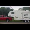 So after hauling home a new 5th wheel project today, I noticed that my new transmission gauge seemed inop. I tore down the dash and found the tap splice I used may have had an intermittent connection ( I hate those things) so I switched out a butt connector and that seemed to fix it. As I was there putting the dash back together, I figured I'd check the trouble codes for fun. It spit out the following: P0622 P0743 P1693 P1765 Now I had noticed wayyy back in fall that the trans had shifted in and out of OD on the highway a few times on a few separate days but quit. I have since then installed a lockup switch on the dash. Would the lockup switch cause the codes because you are messing with the transmission signals- so to speak? I did test the alternator with my MM and got .01- .02 VAC, not alarming. I also read the trouble code trouble shooter on the info pages, but I don't have a scan tool that can freeze frame and what not. Could it be my 3 day old EZ causing this? I don't know how long these codes were present. Any thoughts?
 -
I was driving in hot weather up hill last week (dont know if temp related), when the "Check Engine" light came on, I noticed the volt meter was all the way down to the left most line (same as engine off position). When I arrived at the top and started on the decent; I noticed the overdrive does not work (auto trans), also the cruise control is not working, and the trans appears to slip on take off. Referencing the PCM (power control module) info; the pcm controls the above items, I have not noticed any other items on the list malfunctioning. Before I spend $400 or more for a new pcm, I would like to make sure it is the module or bad connection, ground... What is be best method to confirm the pcm is good or bad? Or is there something else that could cause the above problems? Brian
-
Does anyone have a picture of the pinouts on the pcm?I am looking for #23 orange wire/dark blue tracer.I have a picture of the in's and outs's on a wire diagram,but i am looking for a number block to help me get there faster.Thanks in advance.
-
 Hi, I just joined this site but had visited it for a while now. Lots of good info,Thank you!!! I have found similar threads related to my issue, but seems like thread ends before the problem is resolved or 99% of the time everybody narrow it down to junk vp. I got a 2002, 2500, 6spd, 4x4, qwd cab, with 130k, air dog, 100hp injectors, 3.55 gears, qwad with pulse, 5" pipe, Problem I'm having is driving on highway over 65mph pulling a trailer(rated 14k gross but about 8-10k total) at steady speed , when going up hill truck starts to surge but not much it's noticeable enough to know there is a problem. And if i turn up the fuel box up it gets worse. so it tells me it's fuel related. i got this truck a few years ago, and previous owner has changed vp under warranty, and at that time he put air dog, it may have 30k on pump. i change fuel filter once a year, but only put about 3-5k ml on it a year. other than that it runs relay good starts right up has plenty of power. i thought maybe it could be that transistor in vp but nut sure if i should have codes or can it be bad and not have codes. Any help would be highly appreciated!
 -
 Pcm voltage regulator went out in my truck so I put in an older dodge external v. regulator. Works great at 14.6v until you drive about 5 miles then the check gauges light comes on and voltage reads pegged past 18v. I take readings at fuse block where alternator charging wire is and it is reading 14.6v. what the hell is going on? Voltage regulator is hooked up blue wire 12v switched ignition to cigarette lighter and green is to the plug on alternator. Even put on another ground from vr to ground on battery. Anyone have any suggestions?
 -
Hey all iv been searching all over the internet for a pin out for my 1995 ram 2500 12 valve. the problem im having is all the pin outs are for a 3 plug pcm, mine is only a 1 plug with 60 pins, im trying to diagnose why my pcm has no power or gorund, because the charging system, grid heaters, tach, overdrive, pretty much anything controlled thru that computer is dead, i already changed the ESS engine speed sensor, thats what i was told would cause the problem, and yet still have the same problem, iv traced it to the pcm plug, if i wiggle the plug with the key on, i can hear the grid heaters clicking on an off, if i wedge the plug in an up positon everything works just fine so im trying to figure out what wire is the culpret, please send ur information my way! thanks! --- Update to the previous post... newest information, the check engine light, wait to start light, waterin fuel light and trans temp light are goin crazy comming on and off, as well as relays clicking on the driver side of the hood when i mess with the wires at the pcm, i can even com close to finding the problem cause anthing i touch makes it go crazy, im at a serious loss here please help! THANKS!!!
-
This should work from 1994-1997, not sure about 1998, probably close enough for that one. Basically I needed to trace out every single PCM wire and after 2 hours I got it all written down. If there is a "/", that means it splices into something else as well, hopefully the things that say a/c doesn't throw anyone off . The PCM has 3 big connectors, I am calling them A, B, and C, just like the schematic does. I haven't went out and looked to see which is which but they are color coded (White/Grey/Black). On a more subtle note, if you want to know how your truck is really wired, trace each one yourself I might make a few more of these. It's kinda nice knowing how many or what wires go into the PCM or PDC (power distribution box(the black one on the drivers side fender)) without having to trace them out for an hour. The numbers (PCM-A1 or the like) all correlate with the master wiring diagram which can be downloaded here. 1997 PCM Wiring.pdf 1997 PDC Wiring.pdf
-
Just wondering if anyone knows if any of the wiring harness needs to be replaced when switching from an auto PCM to a manual PCM?
-
I'm going to point out to everyone there is NO WAY to have just a P1693 code present during error code dumping. Yes the P1693 is a companion code and has no really meaning but... "This code indicates there is more code present in the other computer" So if the P1693 is in the P PCU that means there is more codes present in the P ECU. So if there is a P1693 in the P ECU that means there is more codes present in the P PCU. Then even in rare cases seeing the P1693 code in both computers pointing out that both computers have codes. But there is NO WAY for the P1693 to be the only codes present during error code dump. It's totally impossible! The reason I'm posting this is because it seem like everyone is cancelling out at the first P DONE thinking its done. WRONG! There is TWO computers in the truck. P PCU = Powertrain Controller Unit (Passenger side firewall) P ECU = Engine Controller Unit (Driver side of engine block) You should always see both P PCU and P ECU displayed and 2 P DONE's in the display. If you want to see a video of this and how to properly do it please reffer to my web site and watch the video I produced so you can give us acurrate information on your problems your having with your truck. Here is the page with the video of how its done... http://mopar.mopar1973man.com/cummins/2ndgen24v/obd2-error-codes/obd2-error-codes.htm Now the other thing is alot of people are getting error code from OBD II sites or from manuals with the scanners. I'll point out that any code over P1000 is a manufacture specific code that only applies to the that make and model of vehicle so please refer to a proper Factory service manual and get the proper codes. I've got some books listed on my site provided by PDFTown.com http://pdftown.com/Dodge-Ram-2001-Service-Manual.html As for 2nd Gen 24V error codes I copied the error code listing straight out of the Dodge FSM for our truck and made a short PDF file for viewing... http://mopar.mopar1973man.com/cummins/2ndgen24v/obd2-error-codes/error-codes.pdf This will help us diagnose your problem quickly and properly.