


CAN BUS COMMUNICATION
DESCRIPTION
The primary onboard communication network between microprocessor~based electronic control modules in this vehicle is the Controller Area Network (CAN) data bus system. A data bus network minimizes redundant wiring connections; and, at the same time, reduces wire harness complexity, sensor current loads, and controller hardware by allowing each senSing device to be connected to only one module (also referred to as a node). Each node reads then broadcasts its sensor data over the bus for use by other nodes requiring that data. Each node ignores the messages on the bus that it cannot use.
The CAN bus is a two-wire multiplex system. Multiplexing is any system that enables the transmission of multiple messages over a single channel or circuit. The CAN bus is used for communication between most vehicle nodes. However, in addition to the CAN bus network, certain nodes may also be equipped with a dedicated Serial Controller Interlace (SCI) or a K-Line serial link bus to provide direct communication between that node and certain sensor inputs.
There are actually three separate CAN bus systems used in the vehicle. They are designated: the CAN-B, the CAN-C and the Diagnostic CAN-C. The CAN-B and CAN-C systems provide on-board communication between all nodes in the vehicle. The CAN-C is the faster of the two systems providing near real-time communication (500 Kbps), but is less fault tolerant than the CAN-B system. The CAN-C is used typically for communications between more critical nodes, while the slower (83.3 Kbps), but more fault tolerant CAN-B system is used for communications between less critical nodes. The CAN-8 fault tolerance comes from its ability to revert to a single wire communication mode if there is a problem in the bus wiring.
The added speed of the CAN data bus is many times faster than previous data bus systems. This added speed facilitates the addition of more electronic control modules or nodes and the incorporation of many new electrical and electronic features in the vehicle.
The Diagnostic CAN-C bus is also capable of 500 Kbps communication. and is sometimes informally referred to as the CAN-D system to differentiate it from the other high-speed CAN-C bus. The Diagnostic CAN-C is used exclusively for the transmission of diagnostic information between the Totally Integrated Power Module/Central GateWay (TJPM or TIPMCGW) and a diagnostic scan tool connected to the industry-standard 1 B-way Data Link Connector (DLC) located beneath the instrument panel on the driver-side of the vehicle.
The TIPM is located in the engine compartment near the battery. The central CAN gateway or hub module integral to the TIPMs connected to all three CAN buses. This gateway physically and electrically isolates the CAN buses from each other and coordinates the b;-directional transfer of messages between them.
OPERATION
The Controller Area Network (CAN) data bus allows aU electronic modules or nodes connected to the bus to share information with each other. Regardless of whether a message originates from a module on the lower speed CAN-B bus or on the higher speed CAN-C or CAN·D bus, the message structure and layout is similar, which allows the Totally Integrated Power Module/Central GateWay (TIPM or TIPMCGW) to process and transfer messages between the buses. The TIPM also stores a Diagnostic Trouble Code (DTC) for certain bus network faults. All modules (also referred to as nodes) transmit and receive messages over one of these buses. Data exchange between nodes is achieved by serial transmission of encoded data messages. Each node can both send and receive serial data simultaneously. Each digital bit of a CAN bus message is carried over the bus as a voltage differential between the two bus circuits whiCh, when strung together, form a message. Each node uses arbitration to sort the message priority jf two competing messages are attempting to be broadcast at the same time. The voltage network used to transmit messages requires biasing and termination. Each module on the CAN bus network provides its own biaSing and termination. There are two types of nodes used in the CAN bus net.w0rk. On the CAN-C bus, a dominant node has a 120-ohm termination resistance, white a non-dominant (or recessive) node
has about a 2500 to 3000 ohm (2.5 to 3.0 kilohm) termination resistance. The dominant nodes on the CAN·C bus are the TIPM and the Powertrain Control Module (PCM).
The termination resistance of two dominant nodes is combined in parallel to provide a total of about 60 ohms. This resistance value may vary somewhat by application, depending upon the number of non-dominant nodes on the CAN-C bus. On the CAN-D bus (or Diagnostic CAN-C) an of the 60-ohm termination resistance is present in the Central GateWay (TIPMCGW).
NOTE: Termination resistance of a CAN-B node cannot be verified with a Digital Multi-Meter (DMM) or Digital Volt Ohm Meter (DVOM). The transceiver of each CAN-B node connects to termination resistors internally. When the vehicle battery Is disconnected, the internal connections of all CAN Bus node transceivers are switched open, disconnecting the termination resistors. Therefore, the total bus resistance measured under
these conditions will be extremely high or infinite, which does not accurately reflect the actual termination resistance of the CAN-B bus.
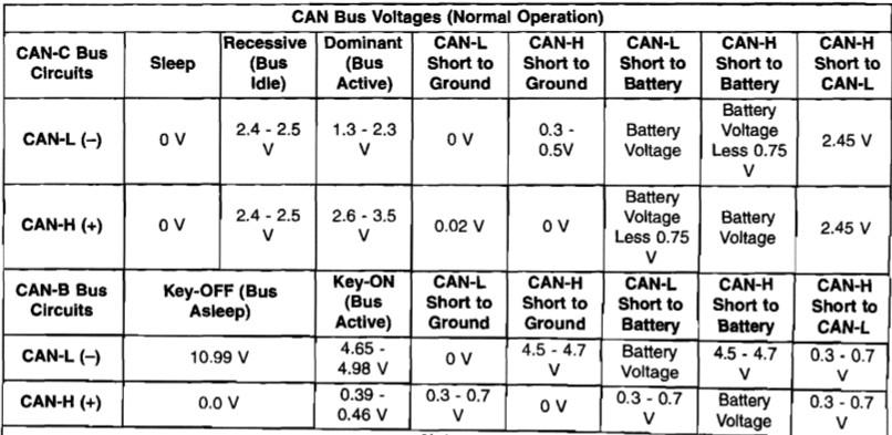
The communication protocol is used for the CAN data bus is a non-proprietary, open standard adopted from the Bosch CAN Specification 2.0b. The CAN-C is the faster of the two primary buses in the CAN bus system, providing near real-time communication (500 Kbps). The CAN bus nodes are Connected in parallel to the two-wire bus using a twisted pair, where the wires are wrapped around each other to provide shielding from unwanted electromagnetic induction, thus preventing interference with the relatively low voltage signals being carried through them. The twisted pairs have between 33 and 50 twists per meter (yard). While the CAN bus is operating (active), one of the bus wires will carry a higher voltage and is
referred to as the CAN High or CAN bus (+) wire, while the other bus wire will carry a lower voltage and is referred to as the CAN Low or CAN bus (-) wire. Refer to the CAN Bus Voltages table.
There are no reviews to display.