


THROTTLE POSITION SENSOR
AUTOMATIC TRANSMISSION ONLY
The throttle position sensor (TPS) is used on the diesel powered engine only when equipped with an automatic transmission. If the TPS is to be replaced on a diesel engine, it must be tested/ adjusted after replacement.
REMOVAL
(1) Disconnect the electrical connector on bottom of TPS (Fig. 34).
(2) Remove the two TPS mounting bolts.
(3) Remove the sensor from bracket.
INSTALLATION
(1) Position the TPS to the mounting bracket. The electrical connector should be facing downward. NOTE: The TPS is spring loaded. After positioning the TPS to its mounting bracket, rotate the TPS on the bracket in a counterclockwise direction until the two bolt holes align.
(2) Install and tighten two bolts.
(3) Connect the electrical connector on bottom of TPS.
(4) Operate the throttle by hand to check for binding.
(5) The TPS voltage must now be tested and (if necessary) adjusted. Refer to the following: Throttle Position Sensor Testing.
THROTTLE POSITION SENSOR TESTING
CAUTION: Before attempting to test the TPS, verify the linkage adjustment dimension (Fig. 35). This dimension MUST be 126.5 mm (5.0 inches) BEFORE testing. For linkage adjustment procedures, refer to Throttle Linkage Adjustment—Diesel Engine. This an be found in the Accelerator Pedal and Throttle Cable section of this group.
CAUTION: Before testing the TPS, verify that the engine is set at correct low idle speed. Refer to Idle Speed Adjustment.
(1) After confirming the correct linkage adjustment and idle speed, proceed to the following:
(2) Attach a paper clip into the center terminal (Fig. 34) of the TPS electrical connector. Do not remove the connector from the TPS for this test.
(3) Attach the positive lead of a voltmeter to this paper clip and the negative lead to a good ground.
(4) Turn the ignition switch to the ON position. Do not start engine.
(5) The voltage at the TPS center terminal should be 1.0 volt (± .2 volt) with linkage at idle position. Atwide open throttle (WOT), the output voltage must be 2.2-to-2.9 volts higher than at idle speed. I f voltage is not correct, proceed to adjusting linkage.
(6) The linkage rod (Fig. 36) connecting the throttle lever to the fuel injection pump lever is adjustable. To prevent damage to the ends of linkage,
attach locking-type pliers to the flat (Fig. 36) located on the linkage rod before loosening locknuts.
(7) Loosen the right-hand-threaded nut (Fig. 36).
(8) Loosen the left-hand-threaded nut (Fig. 36).
(9) Slowly rotate the flat (Fig. 36) on the linkage rod (lengthen or shorten) to achieve 1.0 volt (± .2 volts) on the voltmeter with the linkage in the idle position. At wide open throttle (WOT), the output voltage must be 2.2-to-2.9 volts higher than at idle speed.
DO NOT lengthen or shorten the linkage rod more than 1 mm from the dimension shown in (Fig. 35). I f voltage requirements cannot be met by linkage adjustment (125.6 to 127.6 mm), replace the TPS.
(10) Tighten both nuts after adjustment.
(11) With the engine OFF, operate the throttle from accelerator pedal and check for throttle lever action and binding. Be sure throttle lever stop is against the low idle speed screw after throttle is released.
(12) Be sure of wide open throttle (WOT) when accelerator pedal is pressed to the floor. This is checked by observing throttle lever breakover position. Proceed to the following:
(a) Key OFF and engine OFF for this test.
(b) Two people are needed for this test. From inside of the vehicle, press the accelerator pedal about half-way to the floor. Movement of both the throttle lever and throttle lever-to-injection pump lever linkage rod (Fig. 36) should be observed.
(c) Continue to press the accelerator pedal to the floor. I f throttle lever breakover is operating correctly, the throttle lever-to- injection pump lever linkage rod should have stopped moving while the throttle lever continues to move towards the rear of vehicle.
(13) Again, check and verify low idle speed. Adjust if necessary.
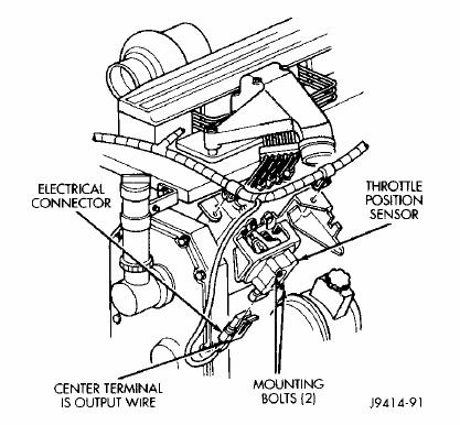
Fig. 34 Throttle Position Sensor—Diesel
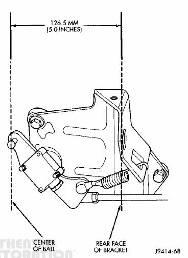
Fig. 35 Linkage Measurement—Diesel

Fig. 36 Throttle Lever Linkage Adjustment—Diesel
There are no reviews to display.