


DIY High Idle using the Stock Cruise Control Servo.
First off, before being able to modify the system for high idle, we must understand what we are working with.
How the cruise control servo works:
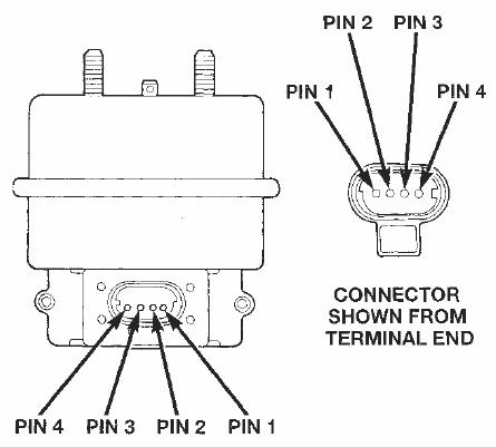
- Pin 4 (black) is permanently grounded.
- Pin 3 (blue/red) gets 12 volts from the PCM, through the brake switch when enabled. This is the main feed for the system, it supplies power to all 3 solenoid valves within the servo. Suppling this pin with power closes the "Dump" valve. Without power to this pin, nothing happens.
- Pin 2 (green/red) gets grounded selectively by the PCM, By grounding this pin, it closes the "vent" valve, thus allowing the servo to hold vacuum. By ungrounding the pin, it will allow vacuum out of the servo decreasing throttle.
- Pin 1 (tan/red) gets grounded selectively by the PCM. By grounding this pin, it opens the 'vacuum' valve allowing vacuum into the servo increasing the throttle.
With our new found knowledge, it has become obvious what needs to be done. But there is something else that we need to remember, if we plan on having cruise control still, we must modify the system in a way that the PCM can still function correctly.
So what do we need to accomplish:
- First things first, we need to make sure be don't back feed the PCM which can cause damage, for this we'll use diodes. Diodes only let current flow in one direction, they're the check valve of the electronics world. By placing diodes in the circuit, it will let the PCM feed the servo as normal, but won't let us back feed it. Perfect!
- We need to supply Pin 3 with 12 volts, I originally thought I could just turn on the stock cruise control system, however it became obvious that the PCM monitors the system closely, and can detect our fooling around and will shut the power back off, not letting us turn it back one again until the next start up.
- We need a way of normally having pin 2 open (not grounded), then ground it when the 'enable' switch is on, but then unground it when the 'lower idle' switch is pressed.
- And then lastely, we need to be able to ground pin 1, very simple, any NO (Normally Open) Switch will do.
- (Optional) When the 'Enable' Switch is off, disable both the other switches.
Keeping that in mind we'll need 4 modes:
Hold Idle Mode (High Idle Enabled): Pin 3 - 12 Volts, Pin 2 - Ground, Pin 1 - Open.
Increase Idle Mode: Pin 3 - 12 Volts, Pin 2 - Ground, Pin 1 - Ground.
Decrease Idle Mode: Pin 3 - 12 Volts, Pin 2 - Open, Pin 1 - Open.
Stealth Mode(Makes the PCM think nothings changed): Pin 3 - Open, Pin 2 Open, Pin 1 - Open.
With all that in mind, here's what I came up with:

Parts List: (This is for my setup, if you wish to change it around, the sky is the limit.)
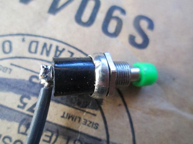
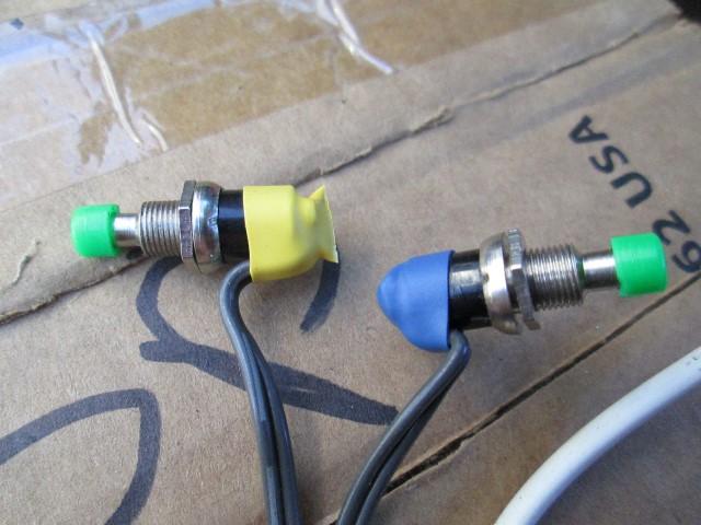
- 2 X Push Button Momentary SPST NO Green Black Red
- 1 X Latching On-Off Switch (lots of options here)
- 1 X Mini Relay SPDT 6V DC.
- 1 X 100 ohm 1 watt Resistor
- 6 X 1N4007 Diodes
- 1 X 4 Wire Cable
- 1 X Assortment of Heat Shrink Tubing -> Great Value
Yes it is a little complex, but if you have one each of NO and NC momentary switches, and a DPST switch as your 'enable' switch, you can eliminate the resister and relay. I did it the way I did for a couple reasons specific to my setup.
If you wish to play around with this circuit, here it is plugged into a circuit simulator, just click the switches, the LED color corresponds with the wire color, and them being on just means they are getting power.
On to actually getting our hands dirty: Before we get started, I'm making a new acronym 'RYHST' (Remember Your Heat Shrink Tubing).
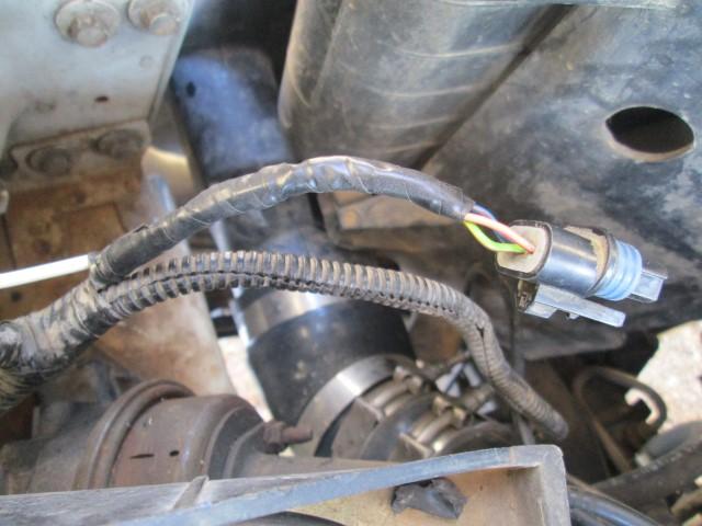
First things first we need to be able to get to the cruise control servo's plug for soldering. You can also solder this in up top where the wires run along the firewall, but I liked doing down there where it's out of the way. To get to it I removed the drivers side battery, which also gives us more room for soldering.
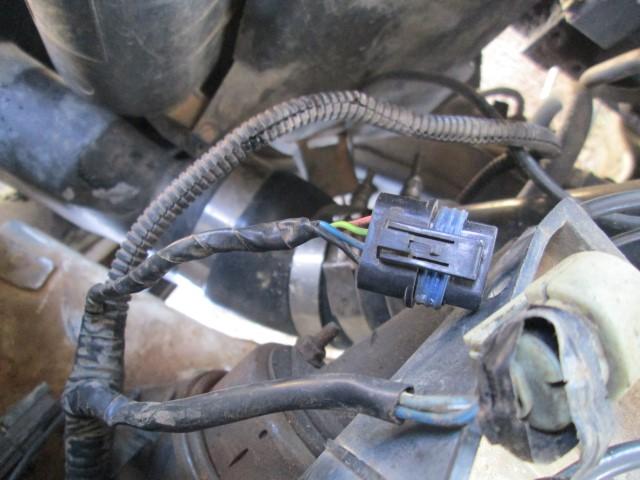
After removing a little electrical tape:
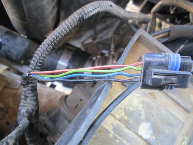
Moment of no return.... Not really, Solder, Duct Tape and WD40 can fix about anything.
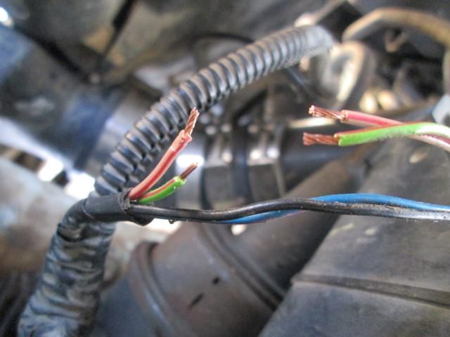
Now for the diodes, I personally went with the 1N4007's as I had a pack of them, they're about as generic as they come. The only difference between these and the 1N4001-6 is the voltage rating, the larger the last number, the higher the voltage rating, for this system any of them will work. The way I figure it, if we're going to protect the PCM with these, might as well protect it all the way to 1000 Volts! When selecting a diode, anything over 100V should be fine. Now for amperage rating, each solenoid has a resistance of 44 ohms, we'll be feeding them 14.5 Volts, minus the voltage drop of the diodes which is ~.6V each, 14.5V-.6V-.6V = 13.3 Volts. Using that info we can calculate the amp draw, 13.3V/44Ω = .3 Amps. Now that is for a single solenoid, the diodes on pin 3 will be powering 2 solenoids (.6Amp) constantly, and all 3 (.9Amp) for a short period of time. These Diodes are rated for continues 1Amp. Normally I would shoot for a larger margin for error, however a higher rated diode will be physically bigger, and because we're soldering relatively thick wires straight to the diode it will have more heat dissipation abilities allowing it to handle more amperage.
- Voltage Rating - 100V minimum (overkill is good) - Check!
- Current Rating - 0.9 Amp Minimum - Check!
- Lastly, Make sure these are just a general diode, not a fancy zener diode or something - Check!
Remember, the diodes are getting soldered to the PCM side of the plug.
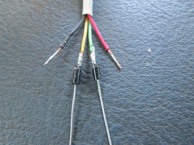
Now to reach into the cab for our switches we'll need a 4 wire cable, I picked a chunk of phone cable, even had good wire colors.
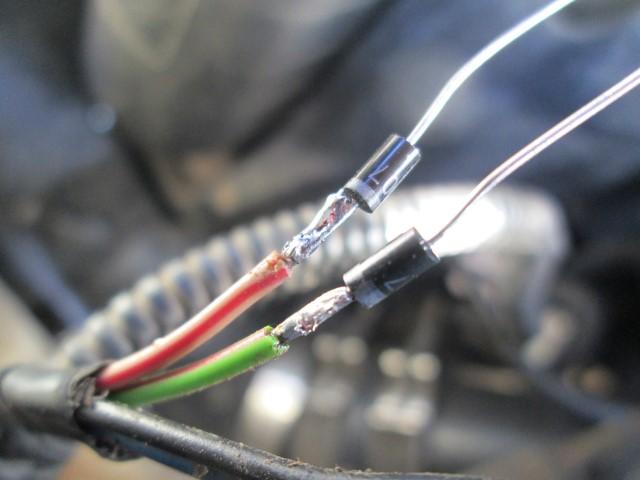
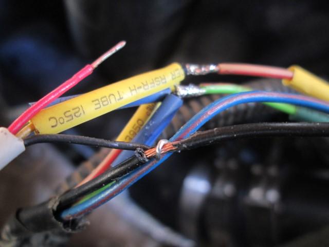
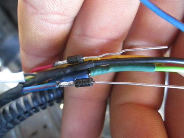
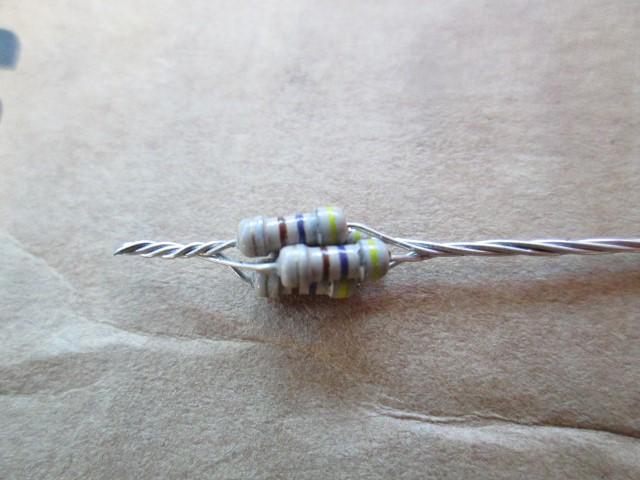
Again, solder the diodes on. Also, remember diodes are directional, so notice the orientation of all the diodes we install. You can tell the orientation by the silver stripe, in the picture below, electrical flow can only go up, if it tries to go down the diodes will close and prevent it from doing so.
RYHST and twist the two sets of diodes together.
When soldering, once done, make sure there are no spikes that are sticking up waiting to puncture the heat shrink tubing. If you have a lot of issues with this, it may be a sign of using to much solder.
Now solder that back to your plug (RYHST)
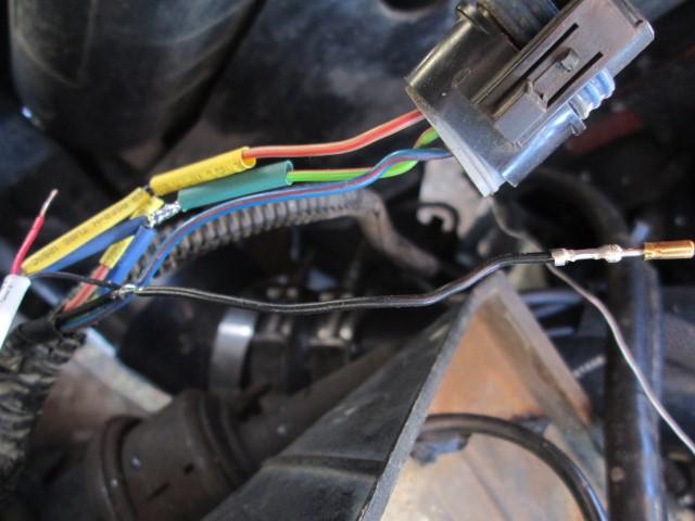
Now the ground wire, just strip a portion of the insulation off, rap the new wire around it and apply solder.
There is a small issue, doing it this way we can't get heat shrink tubing on the wire.
Or maybe we can...
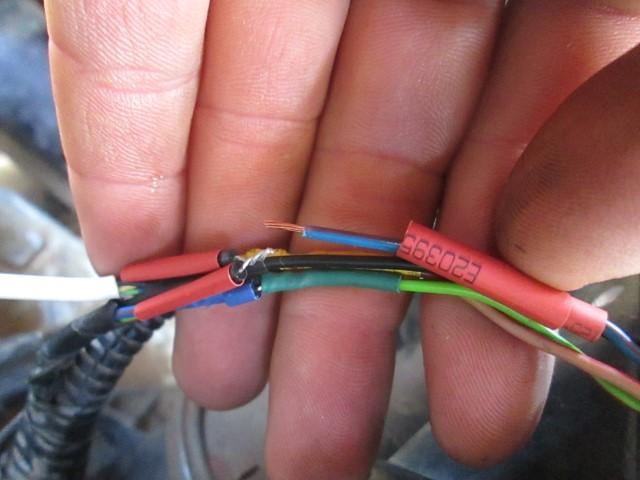
Use a pick (or pocket knife) to pry this red plug out
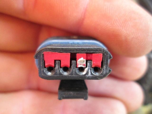

Now there are little fingers holding the pins in, again take your "pick" and pry the one up to get the pin out.
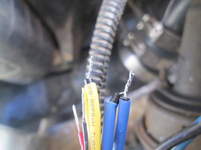
Now for pin #3 (notice that the diodes are facing the opposite direction, that is because this is a power wire where as the others were ground).
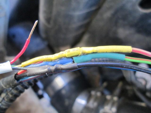
RYHST!
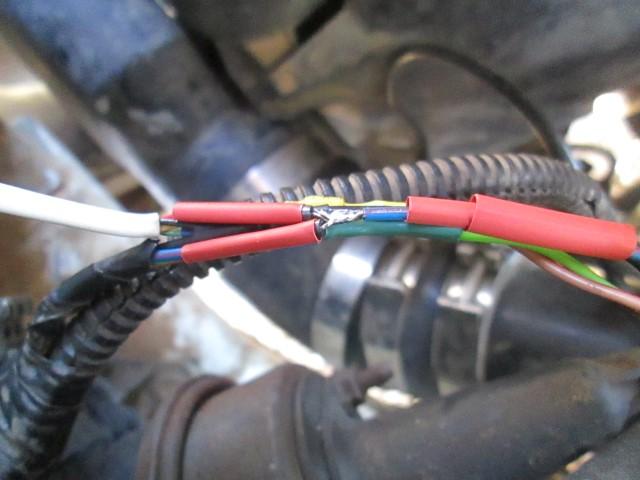
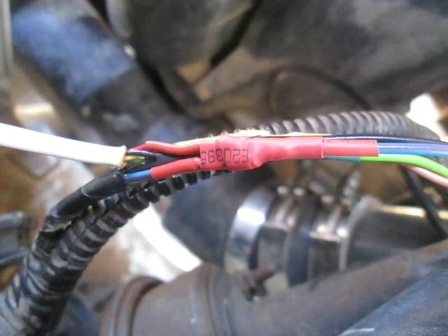
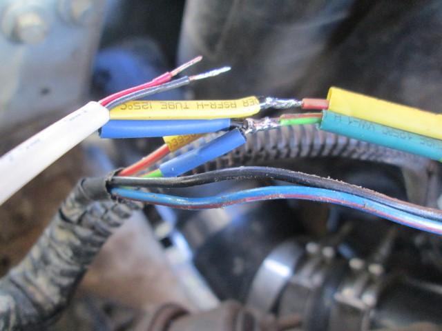
All back together
That's all ready, Time for the truck side, unfortunately I didn't get as many pictures as I would have liked, but they arn't really of use anyway, just a rats nest of wires everywhere. Just stick to the diagram above and you'll be fine!
I'm going to be using 4 resisters instead of one... Why?
It' simple, the design requires a 6 volt relay, so we must split the 12V in half. I measured the relays resistance and got 100 ohm's, so all we need is a 100 ohm resistor. However we need to make sure it is rated for our needs. we'll have half of 14 volts going through it, so 7 volts/100 ohms = .07 amps. .07 amps x 7 volts = .49 watts! So our resistor needs to be rated for at least 1/2 watt, 1 watt would be better. Easy Peizy, however I did not have one on hand... So my fix was to put four 470ohm 1/4watt resistors in parallel. What does that give us? The equivalent to one 117ohm 1watt resistor! That'll do donkey, that'll do.
I had some clearance issues with the switches, so I had to cut the terminals short, but I was able to use some larger heat shrink tubing to protect them pretty well.
Here's the rats nest all soldered up ready to go;
.JPG.821181be1dfbf53448c203f00eef438a.JPG)
Throw a little electrical tape at it and it's ready to call the dash it's home!
.JPG.623b491799aa14fde30cdf484d29a4e3.JPG)
And Installed:
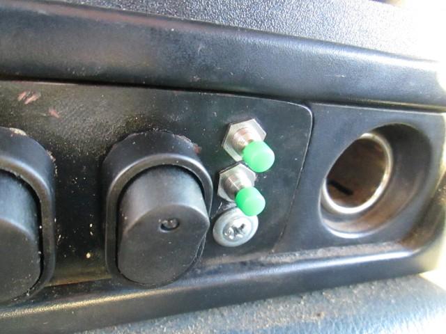
-
 3
3
There are no reviews to display.