This article covers building a simple Arduino device that will buffer APPS input from the pedal to the ecm. The end result is a slow but steady increasing TPS input to the ECM regardless of how quickly the driver modulates throttle input. If the driver goes from idle to %100 throttle this device will slowly roll into the throttle, at a configured delay, to prevent smoke.
This device can also prevent barking by using the same logic in reverse.
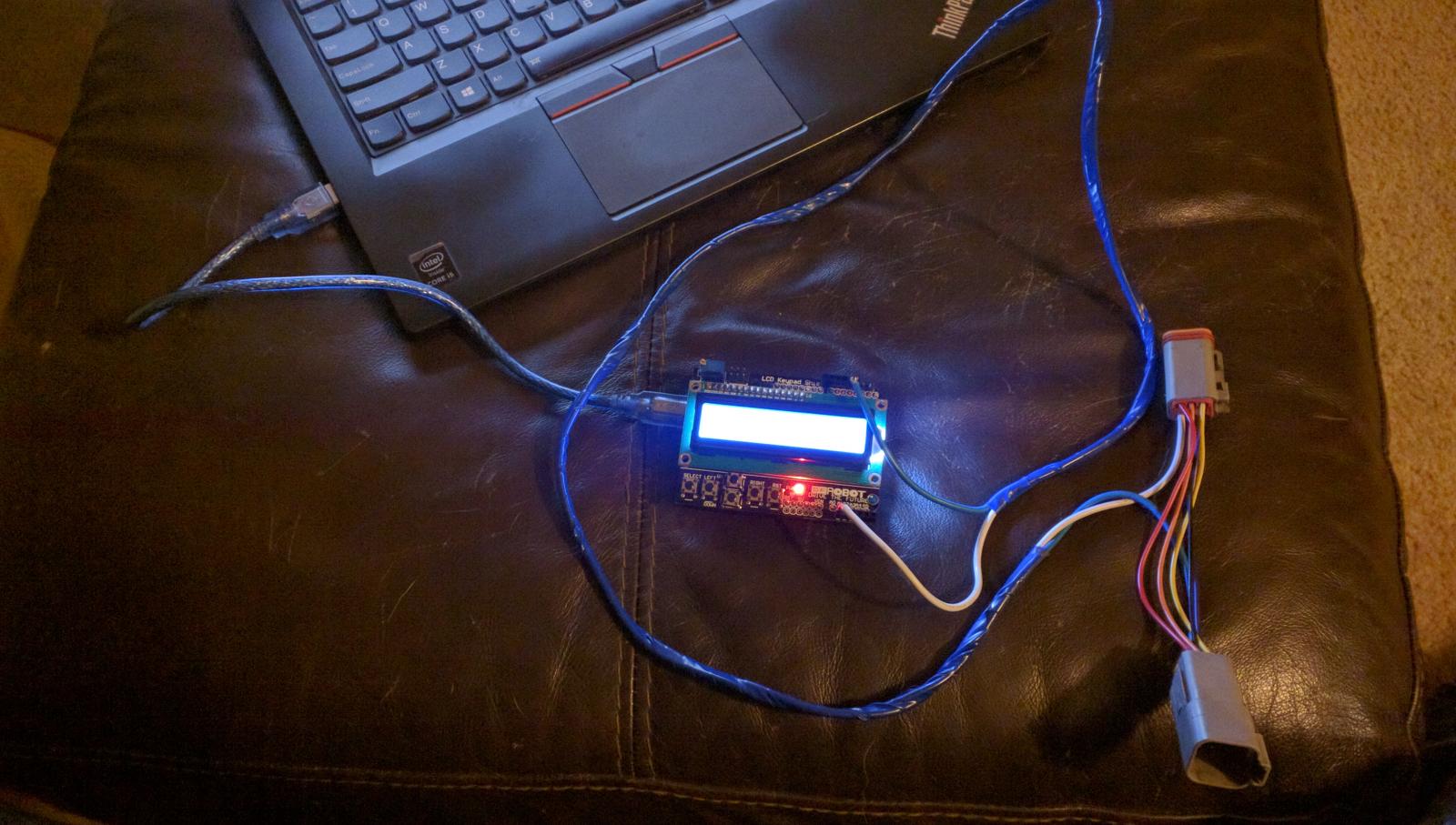
What you will need for this is
- Arduino Uno with a button / LCD shield http://www.ebay.com/itm/UNO-R3-BOARD-LCD-BUTTON-SHIELD-CABLE-ARDUINO-COMPATABLE-PREPROGRAMMED-/322124430521?hash=item4b001cbcb9:g:ulAAAMXQpPhTlIkP
- Deutsch dt 6 plugs http://www.ebay.com/itm/321335296062?_trksid=p2060353.m2749.l2649&ssPageName=STRK%3AMEBIDX%3AIT
- ~30" of 14 - 16 gauge wire. More or less to remote mount the unit in cab
- 12v power source for arduino, I would suggest usb car charger to usb B plug
Connecting the Unit,
Stack the arduino with the button shield, The pins should line up
The TPS input from the apps ( white wire) plugs into A0 on the arduino board, and should be pin 3 on the female end of the DT -6 plug that plugs into the apps sensor.
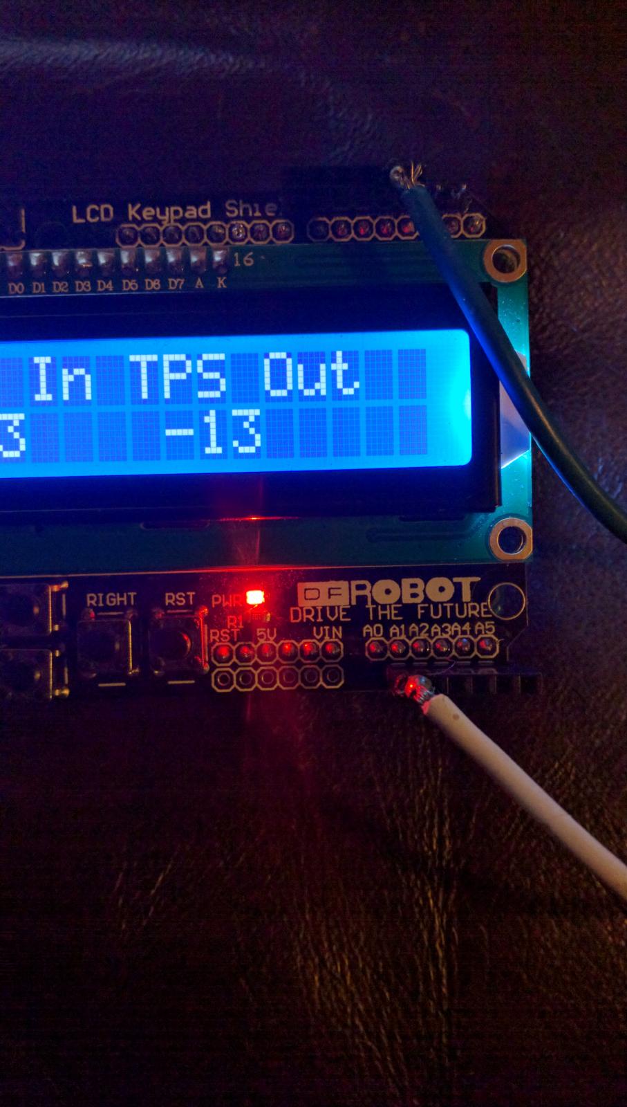
The TPS output from the arduino ( blue wire) plugs into pin 3 on the arduino, and should be pin 3 on the male end of the dt-6 Plug that plugs into the OEM wire that leads to the ecm.
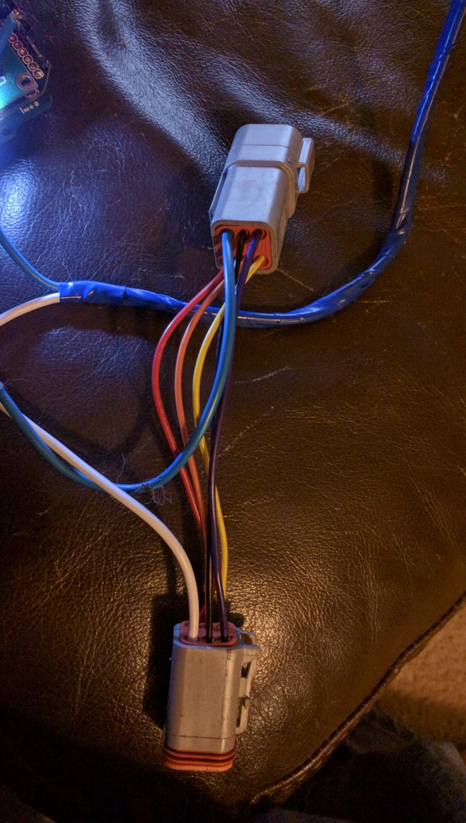
All other wires between the DT-6 plugs are pass through wires, IE; pin 1 to pin 1
Upload this Code to the arduino using a USB cable and the arduino software
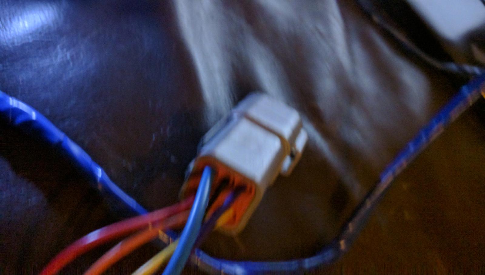
unplug the OEM dt-6 connector from the APPS sensor, plug in the arduino pig tail to the apps and the OEM dt-6 plug that leads to the ecm.
Use,
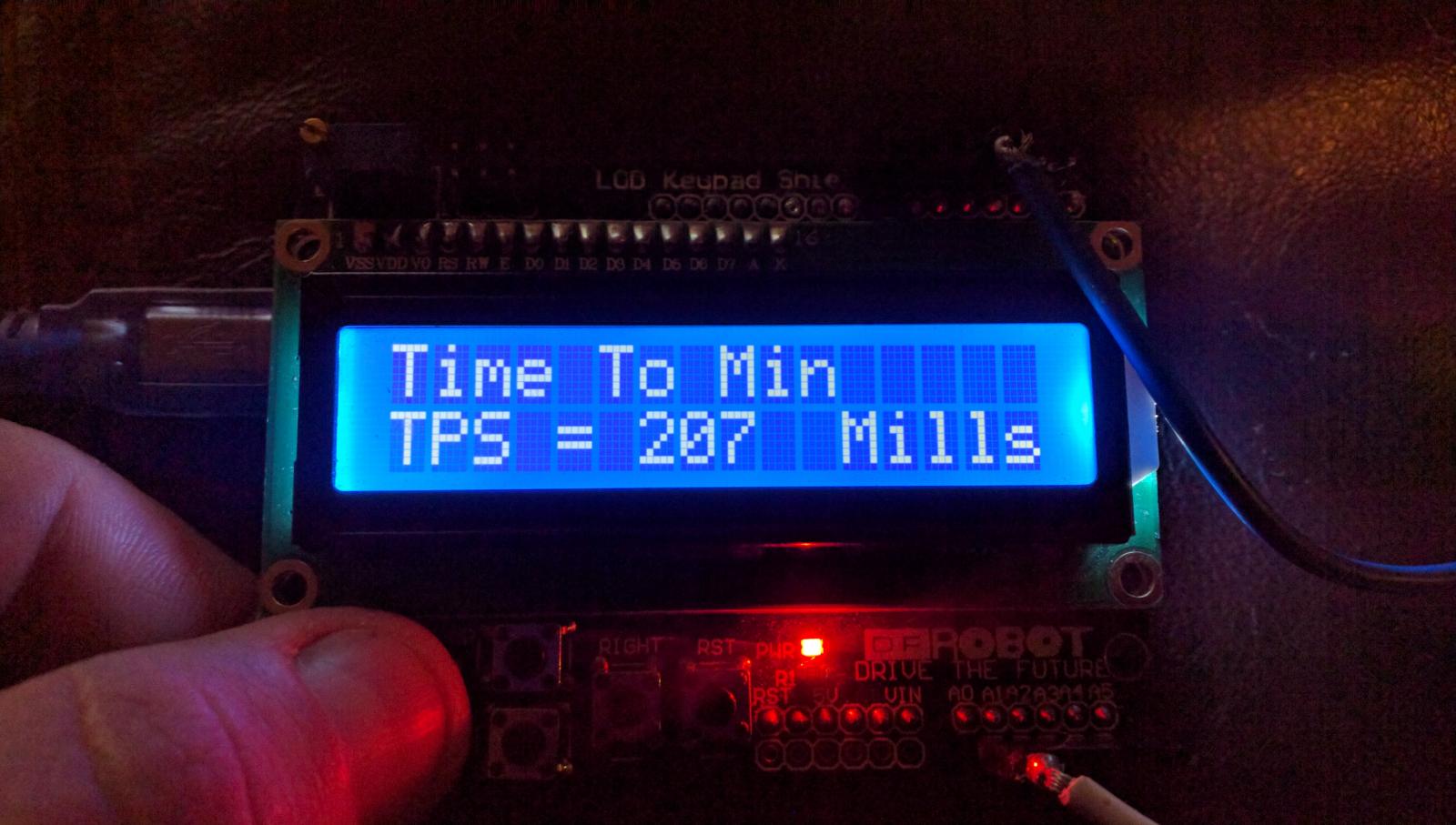
Use the far left button to set the buffer for increasing throttle, then use the up and down to increase or decrease between 1 and 2000 ms.
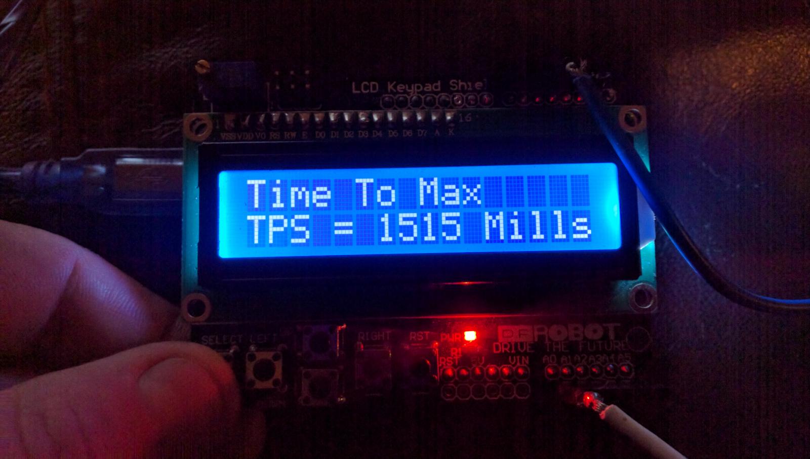
To set the buffer for decreasing TPS use the 2nd to left button to set the mode, then use the up and down button to increase or decrease between 1 and 500 ms.
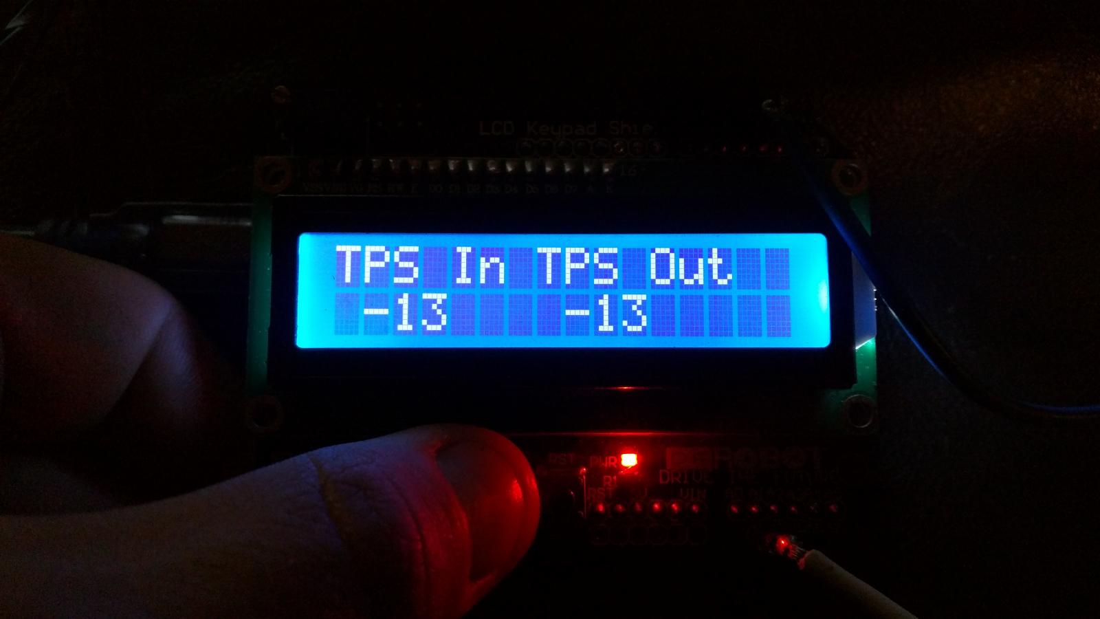
to see the inputted TPS vs the Outputted TPS use the 2nd to right button
"TPS In" is what the driver commanded for a position, TPS Out is what the arduino outputted to the ecm. You should see the output follow the input.



There are no reviews to display.