


The instrument cluster actuator test will put the instrument cluster into its self-diagnostic mode. In this mode the instrument cluster can perform a self diagnostic test that will confirm that the instrument cluster circuitry, the gauges, and the CCD data bus message-controlled indicators are capable of operating
as designed. During the actuator test the instrument cluster circuitry position each of the gauge needles at various calibration points, illuminate each of the segments in the Vacuum-Fluorescent Display (VFD), and turn all of the CCD data bus message controlled indicators on and off.
Successful completion of the actuator test will confirm that the instrument cluster is operational. However, there may still be a problem with the CCD data bus, the Powertrain Control Module (PCM), the Engine Control Module (ECM), the Airbag Control Module (ACM), the Controller Anti-lock Brake (CAB), or the inputs to one of these electronic control modules.Use a DRBIII scan tool to diagnose these components.
Refer to the appropriate diagnostic information.
1. Begin the test with the ignition switch in the Off position.
2. Depress the odometer/trip odometer switch button.
3. While still holding the odometer/trip odometer switch button depressed, turn the ignition switch to the On position, but do not start the engine.
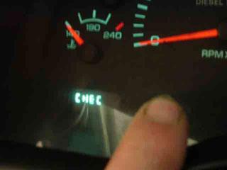
4. Keep the odometer/trip odometer switch button depressed for about ten seconds, until CHEC appears in the odometer display, then release the odometer/trip odometer switch button.
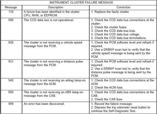
5. A series of three-digit numeric failure messages may appear in the odometer display, depending upon the failure mode. If a failure message appears, refer to the Instrument Cluster Failure Message chart for the description and proper correction. If no failure message appears, the actuator test will proceed as described in Step 6.
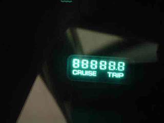
6. The instrument cluster will begin the Vacuum Fluorescent Display (VFD) walking segment test. This test will require the operator to visually inspect each VFD segment as it is displayed to determine a pass or fail condition. First, all of the segments will be illuminated at once; then, each individual segment of the VFD will be illuminated in sequence. If any segment in the display fails to illuminate, repeat the test to confirm the failure. If the failure is confirmed, replace the faulty instrument cluster. Following completion of the VFD walking segment test, the actuator test will proceed as described in Step 7.
7. The instrument cluster will perform a bulb check of each indicator that the instrument cluster circuitry controls. If the wait-to-start indicator does not illuminate during this test, the instrument cluster should be removed. However, check that the incandescent bulb is not faulty and that the bulb holder is properly installed on the instrument cluster electronic circuit board before considering instrument cluster replacement. If the bulb and bulb holder check OK, replace the faulty instrument cluster. Each of the remaining instrument cluster circuitry controlled indicators except the cruise indicator are illuminated by a Light Emitting Diode (LED). If an LED or the cruise indicator in the VFD, fails to illuminate during this test, the instrument cluster must be replaced. Following the bulb check test, the actuator test will proceed as described in Step 8.
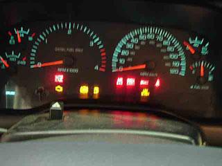
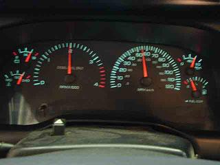
8. The instrument cluster will perform a gauge actuator test. In this test the instrument cluster circuitry positions each of the gauge needles at three different calibration points, then returns the gauge needles to their relaxed positions. If an individual gauge does not respond properly, or does not respond at all during the gauge actuator test, the instrument cluster should be removed. However, check that the gauge terminal pins are properly inserted through the spring-clip terminal pin receptacles on the instrument cluster electronic circuit board before considering instrument cluster replacement. If the gauge terminal connections are OK, replace the faulty instrument cluster.
9. The actuator test is now completed. The instrument cluster will automatically exit the self-diagnostic mode and return to normal operation at the completion of the test, if the ignition switch is turned to the Off position during the test, or if a vehicle speed message indicating that the vehicle is moving is received from the PCM on the CCD data bus during the test.
10. Go back to Step 1 to repeat the test, if required.
There are no reviews to display.