


INTAKE GRID HEATER
OPERATION
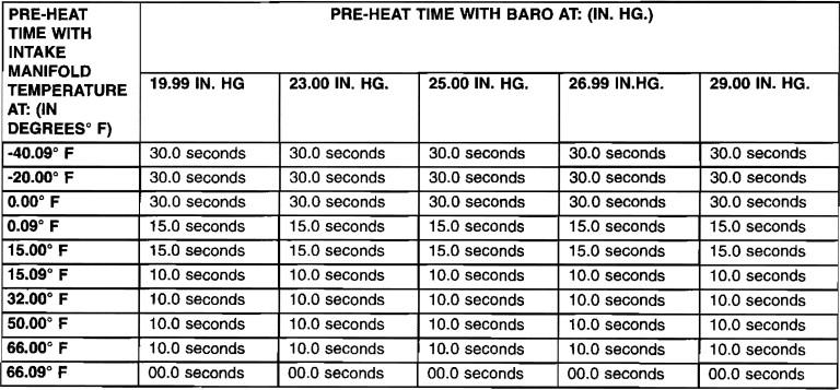
The air heater element is used to heat incoming air to the intake manifold. This is done to help engine starting and improve driveability with cool or cold outside temperatures. Electrical supply for the air heater element is controlled by the Engine Control Module (ECM) through the air heater relay. Refer to Intake Manifold Air Heater Relay for more information. A heavy-duty cable connects the air heater element to the air heater relay. This cable will supply 12-volts to an individual' heating element within the heater block assembly. The following chart displays the pre-heat, or turn-on times (in seconds) of the wait-to-start lamp. If the intake manifold temperature is above 66.09 degrees Fahrenheit, the wait-to-start lamp will not illuminate. Consequently, the intake air heater element will not be activated.
WAIT-TO-START LAMP TURN ON TIMES
REMOVAL
If servicing the heater element, the entire block/element assembly (integrated intake cover) must be replaced.
1. Disconnect both negative battery cables at both batteries. Cover and isolate ends of both cables.
2. Remove both the intake manifold air intake tube (above injection pump), and its rubber connector hose.
3. Remove fuel rail and high-pressure fuel lines. Refer to Fuel Rail Removal.
4. Loosen clamp securing EGR crossover tube to EGR valve. Also, loosen opposite end of EGR crossover tube. Remove clamp from intake connection.
5. Remove air intake connection mounting bolts.
6. Remove air intake connection.
7. Remove heater cable nut and disconnect heater cable from stud.
8. Disconnect electrical connectors.
9. Disconnect crankcase vent line at top of valve cover.
10. Disconnect crankcase pressure sensor electrical connector.
11. Disconnect engine oil dipstick tube bracket.
12. Remove mounting bolts and remove heater element assembly.
13. Remove and discard gasket.
INSTALLATION
1. Clean top of intake manifold and bottom of heater assembly.
2. Install new gasket.
3. Position assembly to top of manifold.
4. In~tall mounting bolts. TIghten to 24 N·m (18 ft. Ibs.).
5. Attach engine oil dipstick t~be bracket.
6. Install fuel rail and all high-pressure fuel lines. Refer to Fuel Rail Installation.
7. Position air intake connection.
8. Install air intake connection mounting bolts. TIghten bolts to 24 N·m (18 ft. Ibs.).
9. Install new EGR crossover tube gaskets to crossover tube.
10. lighten crossover tube clamps.
11. Connect heater cable to stud.
12. Install heater cable nut.
13. Connect electrical connectors.
14. Connect crankcase vent line at top of valve cover.
15. Connect crankcase pressure sensor electrical connector.
16. Connect rubber connector hose (2) and intake tube to air intake housing. Tighten clamp bolts to 11 N·m (100 in. Ibs.) torque.
17. Connect both negative battery cables at both batteries.
There are no reviews to display.