


CP3 INJECTION PUMP
DESCRIPTION
A Robert Bosch high-pressure CP3 fuel injection pump is used. The CP3 pump is attached to the back at the timing gear housing at the left ftront side of the engine.
OPERATION
The CP3 fuel injection pump supplies high pressure to the fuel rail independent of engine speed. This high pressure is then accumulated in the fuel rail. High-pressure fuel is constantly supplied to the injectors by the fuel rail. The Engine Control Module (ECM) controls the fueling and timing of the engine by actuating the injectors. Fuel enters the system from the electric fuel transfer (lift) pump, which is located in the fuel tank. Fuel is forced through the fuel filter element and then enters the Fuel Pump/Gear Pump. which is attached to the rear of the CP3 fuel injection pump. The Fuel Pump/Gear Pump is a low-pressure pump and produces a minimum pressure of 440 kpa (64psi). Fuel then enters the CP3 fuel injection pump. Low-pressure fuel is then supplied to the FCA (Fuel Control Actuator).
The FCA is an electronically controlled solenoid valve. The ECM controls the amount of fuel that enters the high-pressure pumping chambers by opening and closing the FCA based on a demanded fuel pressure. The FPS (Fuel Pressure Sensor) on the fuel rail provides the actual fuel pressure. When the actuator is opened, the maximum amount of fuel is being supplied to the CP3 fuel injection pump. Any fuel that does not enter the injection pump is directed to the cascade overflow valve. The cascade overflow valve regulates how much excess fuel is used for lubrication of the pump and how much is returned to the tank through the drain manifold. Fuel entering the injection pump is pressurized to between 200-1800 bar (2901 - 26107 psi) by three radial pumping chambers. The pressurized fuel is then supplied to the fuel rail.
REMOVAL
CAUTION: Cleanliness cannot be overemphasized when handling or replacing diesel fuel system components. This especially includes the fuel injectors, high-pressure fuel lines and CP3 fuel injection pump. Very tight tolerances are used with these parts. Dirt contamination could cause rapid part wear and possible plugging of fuel injector nozzle tip holes. This, in turn, could lead to a possible engine misfire. Always wash/clean any fuel system component thoroughly before disassembly and then air dry. Cap or cover any open part after disassembly. Before assembly, examine each part for dirt, grease or other contaminants and clean if necessary. When installing new parts, lubricate them with clean engine oil or clean diesel fuel only.
1. Disconnect both negative battery cables at both batteries. Cover and isolate ends of both cables.
2. Remove intake manifold air intake tube (above injection pump) and its rubber connector hose.
3. Remove accessory drive belt.
4. Thoroughly clean rear of injection pump, and attachment points for its fuel lines. Also clean the opposite ends of these same lines at their attachment points.
5. Disconnect quick-connect fitting by pressing on button.
CAUTION: Whenever a fuel line fitting is connected to. a secondary fitting, always use a backup wrench on the secondary fitting. Do not allow the secondary fitting to rotate.
6. Remove high-pressure fuel line to fuel rail.
7. Remove banjo bolt.
8. Disconnect FCA (Fuel Control Actuator) electrical connector.
9. Remove line clamp.
10. Remove fuel pump drive gear access cover with a 3/8" drive ratchet. Access cover is threaded to timing gear cover.
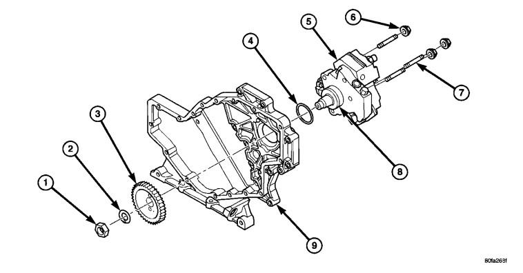
11. Remove fuel pump drive gear mounting nut and washer.
12. Attach C3428B, or L4407A (or equivalent) gear puller to pump drive gear with 2 bolts, and separate gear from pump (a keyway is not used on this particular injection pump). Leave drive gear hanging loose within timing gear cover.
13. Remove three injection pump mounting nuts (6), and remove pump from engine.
INSTALLATION
1. Inspect pump mounting surfaces at pump and mounting flange and pilot bore for nicks, cuts or damage. Inspect O-ring surfaces for nicks, cuts or damage.
2. Clean injection pump mounting flange and pilot bore at gear housing. Also clean front of injection pump.
3. Install new rubber O-ring (square) into machined groove at pump mounting area.
4. Apply clean engine oil to injection pump O-ring and pilot bore only. The machined tapers on both injection pump shaft and injection pump gear must be absolutely dry, clean and free of any dirt or oil film. This will ensure proper gear-to-shaft tightening.
5. Clean pump gear and pump shaft at machined tapers with an evaporative type cleaner such as brake cleaner.
6. FUEL INJECTION PUMP PHASING: Perform the following phasing procedure anytime the injection pump has been removed and re-installed.
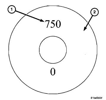
7. Locate the end of the fuel injection pump shaft. Two numbers (750 and 0) are stamped into the end of the shaft.
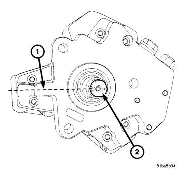
8. Rotate the injection pump shaft until the number 5 (located in the center of number 750) is positioned at 9 o'clock.
9. Position injection pump to mounting flange on gear housing while aligning injection pump shaft through back of injection pump gear. Be sure the number 5 is still at the 9 o'clock position.
10. Bring the engine to TOe position. Do this by rotating the crankshaft until the TDe mark on the crankshaft damper is at 12 o'clock position. It does not matter if cylinder #1 or #6 is at top. Again, check to be sure the number 5 is still at the 9 o'clock position. Rotate pump shaft accordingly.
11. After pump is positioned flat to mounting flange, install three pump mounting nuts and tighten finger tight
only. Do not attempt a final tightening at this time. Do not attempt to tighten (pull) pump to gear housing
using mounting nuts. Damage to pump or gear housing may occur. The pump must be positioned flat to
its mounting flange before attempting to tighten three mounting nuts.
12. To prevent damage or cracking of components. install and tighten nuts in the following sequence:
a. Install injection pump shaft washer and nut to pump shaft. Tighten nut finger tight only
b. Do preliminary (light) tightening of injection pump shaft nut (1).
c. Tighten three injection pump mounting nuts to 24 N·m (18 ft. Ibs.).
d. Do a final tightening of pump shaft nut to 105 N·m (77 ft. Ibs.).
13. Install drive gear access cover using a 3/8" drive ratchet. Access cover is threaded to timing gear cover. Tighten to 8 N·m (71 in. Ibs.) torque.
14. Install fuel return line. Tighten banjo bolt to 24 N·m (18 ft. Ibs.) torque.
15. Install quick-connect fitting.
16. Install fuel line (injection pump-to-fuel rail). Using a back up wrench, tighten fitting at fuel pump to 40 N·m (30 ft. Ibs.) torque. Tighten fitting at fuel
rail to 40 N·m (30 ft. Ibs.) torque.
17. Install clamp.
18. Connect Fuel Control Actuator (FCA) electrical connector to rear of injection pump.
19. Install rubber intake manifold air intake tube. Tighten clamps .
20. Install accessory drive belt.
21. Connect both negative battery cables to both batteries.
22. Check system for fuel or engine oil leaks.
There are no reviews to display.