Eco77
Unpaid Member
-
Joined
-
Last visited
Everything posted by Eco77
-
Thanks everyone for the knowledge and the willing to help.
-
thanks guys, you use the max9924 in order to sample the car's motor rpm and feed it back to the Arduino's pin 2 (if i remember right). according to Me78569 if I close the switch (pin7 to ground), the pot effect directly on the vanes without the need to calculate the RPM and so, am I right? I'm looking for someone who succeed in operating the actuator on the table and can share with us what is the right process without the need to connect the actuator to the cars turbo. anyway other thoughts will be great :-) and we have a winner !!!!! so, few minutes ago I wrote that I'm looking for more ideas and now I'm happy to tell you I succeed to control the actuator. so, first of all, the actuator must be calibrated in order to be control by the Arduinos software. after the calibration I was able to control the movements with the boost pot. I'll try to upload short video of what I did so everyone can learn. sorry for the video resolution.... calibrating the actuator and control it 2.mp4
-
ok, thanks. btw what can bus shield is working for you? if anyone think of other solution please let me know. thanks again one more thing, is anyone succeed to run the actuator on the table without calibrating him first?
-
Hi, It's a good question!! when I'm sending the calibration command my motor rotate only to one direction, I believe its happen because he can't find the limits.. maybe he goes to "shutdown" state and that's why I need to recycle the power after every calibration command.... So what you actually saying is only after the calibration success (moving on both side and hitting the limits) I can effect the motors movement with the whole circuit.. its a good way of thinking.... thank you very much, I must try it !
-
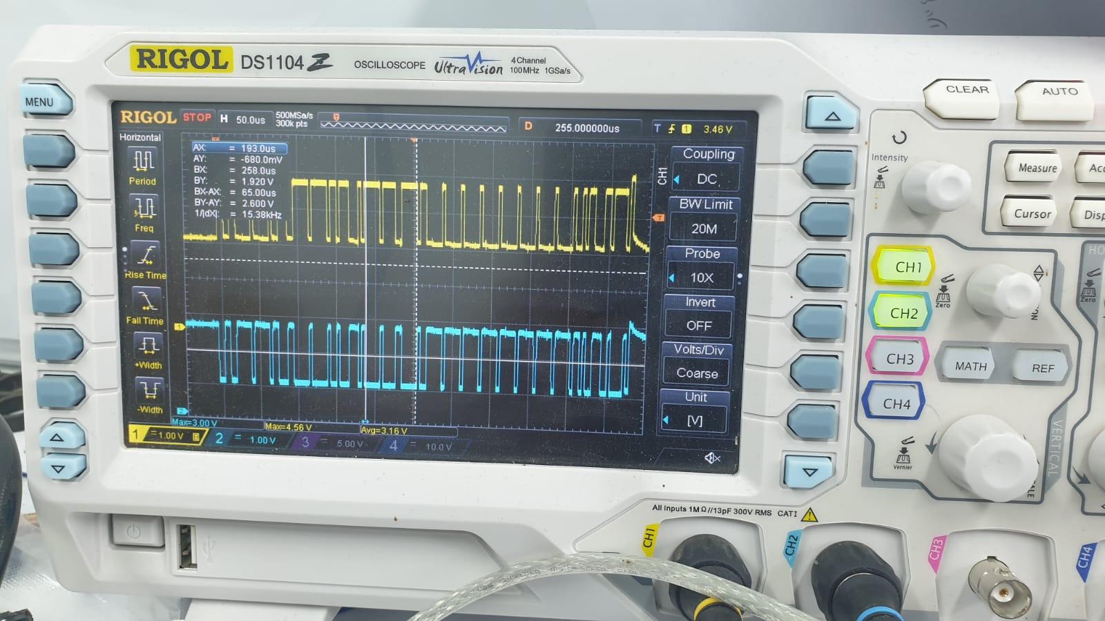
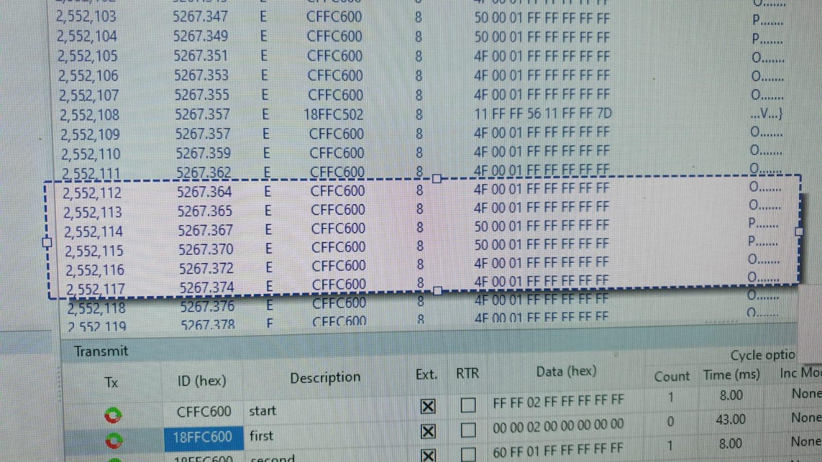
you right, when pin 7 is grounded the pot is changing the can bus message dramatically. but still nothing happen when pin 7 is grounded this is the can bus message
-
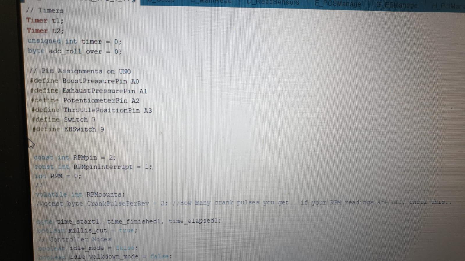
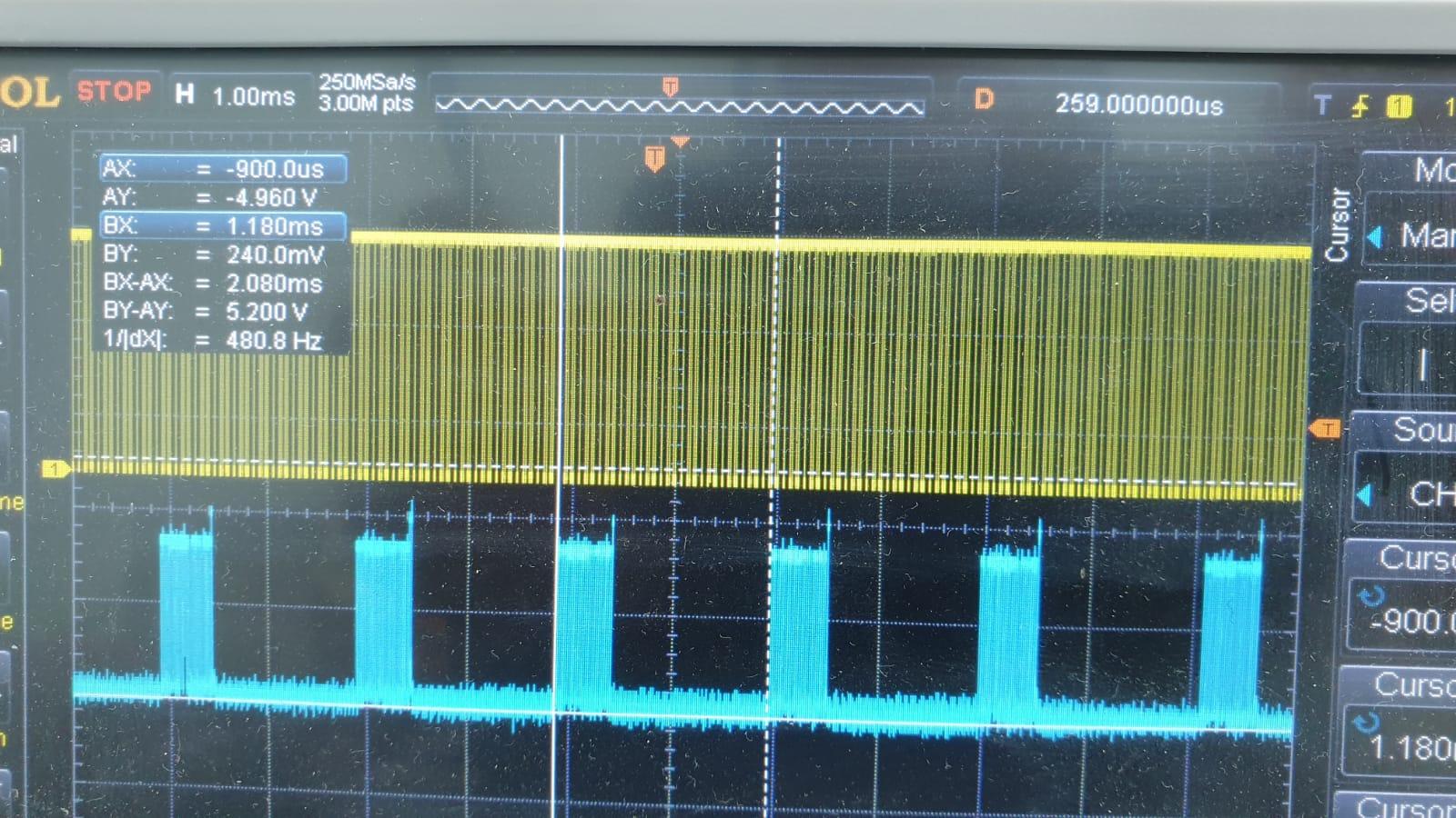
thanks for your reply, according the code you use only pins A0, A1,A2,A3,7,9,2,1 so maybe you used the push pull pot on another code. you right about that, i remember I read somewhere that can messages should be every 10ms, i capture my communication with my scope and the can messages are every 2.080ms so i believe its not the problem. can you or someone else can upload simple code for moving the motor with only one pot? in the past i took the calibration code and changed it to read the pot and send the command to the vans, but with no success...
-
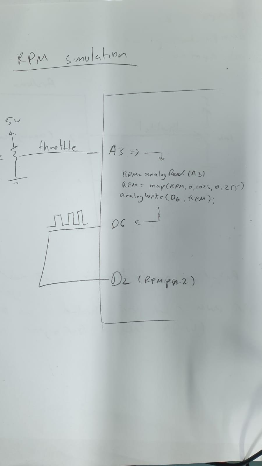
Great Work! thanks for your reply. I didn't connect the rpm sensor, I saw in the code it was in comment. can the stand alone tester work without the rpm input? Is there a way to simulate this sensor, lets say sample the throttle value that is corelate to the rpm value and insert it to pin 2 (as written in the code)? I'm not sure what did you mean by that, you want me to send a canbus a command in order to toggle a led? I can try it, but I believe my communication is working well after I sent the calibration command : 0x0ff0600,extID,8, 0x00,0x00,0x02,0xff,0xff,0xff,0xff,0xff - and the motor rotate to one direction. when I rotate the pot I can see the number changing. so I know the can bus its ok. so, instead of sampling the outside potentiometer (pot), you suggest to sample the boost pot(A0) divide by 2 and send it to the final_vane_position? void set_turbo_position() { //final_vane_position = vane_position; //original code final_vane_position = (analogRead(A0)/2); what we want to accomplish by that? I tried it without any change.... i dont have the max9924 chip so i tried to simulate the rpm by sampling the throttle pin(A3) and send it as PWM to pin 2 (RPMpin2) - what do you think about that? can it work?
-
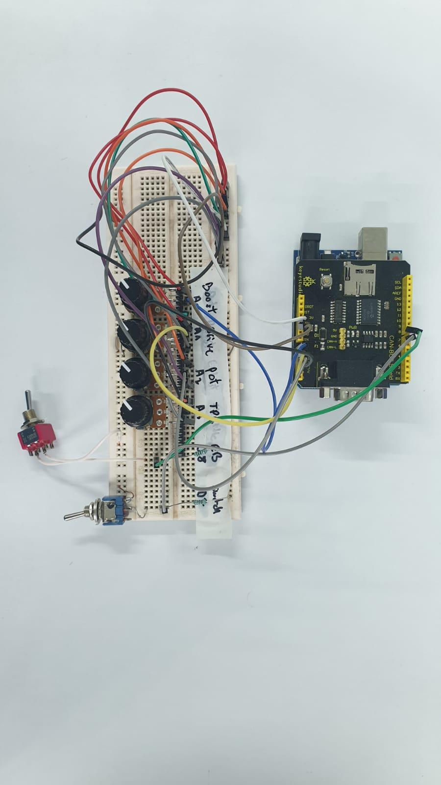
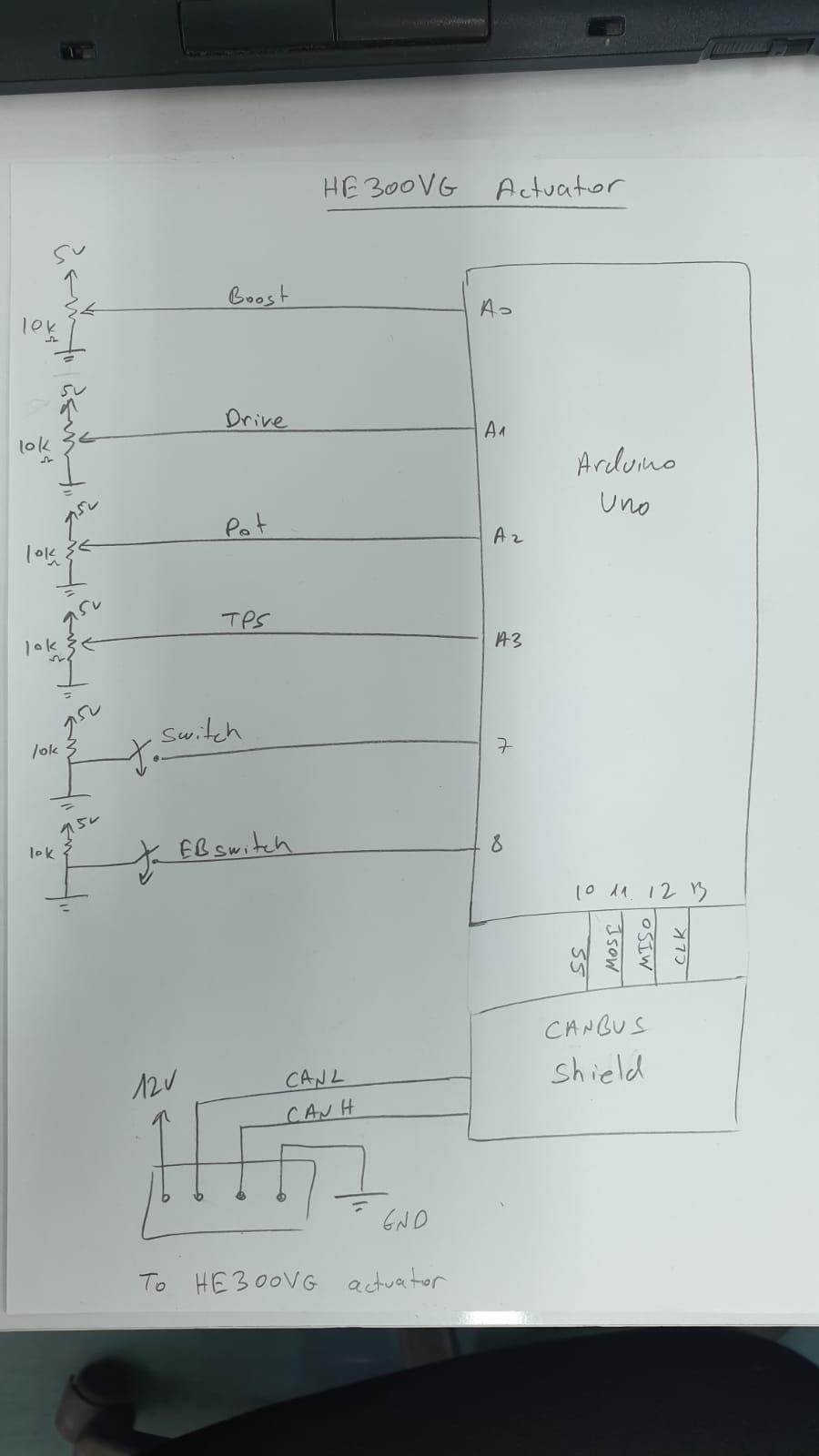
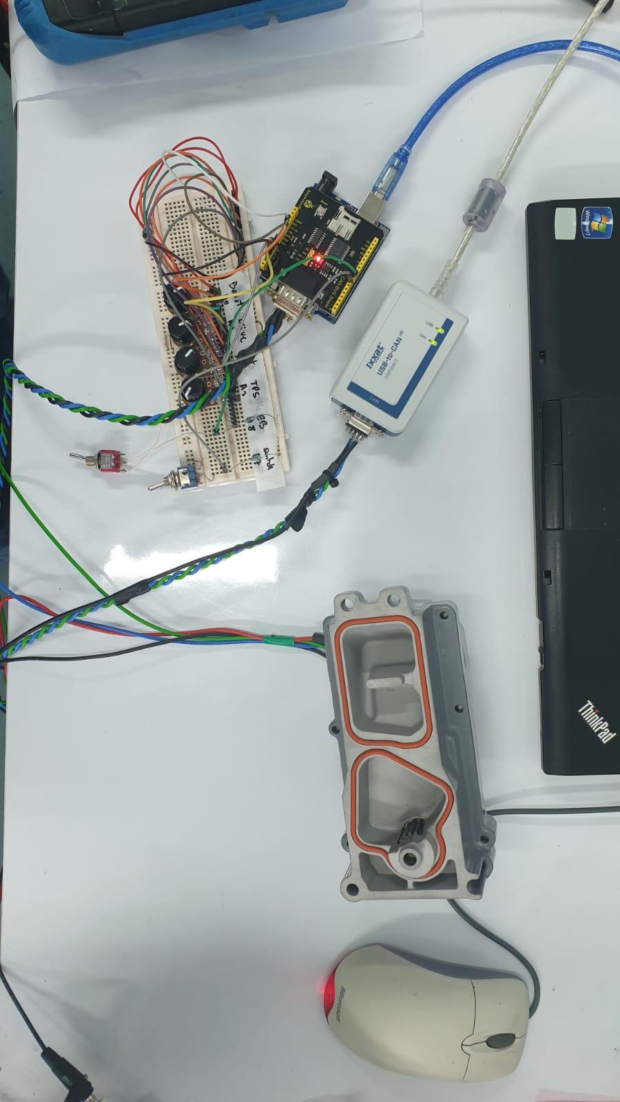
Hi Everyone, I’m following this forum for long time and I wanted to thanks everyone for sharing their knowledge and experience, I learn a lot from you guys, so thank you very much. Currently I’m working on refurbished Holset He300VG turbo actuator, and I’ll be glad if someone can assist me little with controlling the motor. I’m using 12v\10A power supply. I connected everything according the instruction. (On holset main plug the connection are: (GND – CanL – CanH – 12v). (See pic) I sent the calibration code: (CFFC600, extID , 8,FF FF 02 FF FF FF FF FF) And I can see the motor rotating to one direction as it supposed to do, after that I must recycle the power. I connected my Arduino to can bus shield and then connect it to 4 potentiometers + 2 on\off switches. The sensor connection are: Boost pot – A0 Drive pot – A1 Pot – A2 TPS - A3. “Switch” connect the GND to digital pin 7 “EBswitch” connect the GND to digital pin 8 (just to make sure pin 9 is not used by the SPI (See pic) I upload the A_HE351Mainfreq_TPS 1.11 sketch (not the 1.12), the LCD has some problems so I comment his lines. My can bus shield use pin 10 to communicate with the Arduino. Next I checked the can bus messages using Ixxat (usb to can). (See pic) And I can see the numbering changing when I move the pots and switches. The problem is that the motor is not rotating left or right. I saw on the sketch : //const int RPMpin = 2; //const int RPMpinInterrupt = 1; //int RPM = 0; // //volatile int RPMcounts; //const byte CrankPulsePerRev = 2; //How many crank pulses you get.. if your RPM readings are off, check this.. I connected everything in my lab so I don’t have RPM reading, can the actuator work properly without these readings? Maybe you have an idea what else can I do? I upload some pictures, may be it can help...