


grib
Unpaid Member
-
Joined
-
Last visited
-
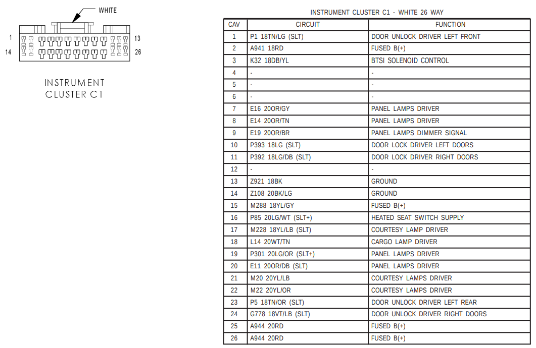
Apparently, there is a preliminary diagnosis step that is recommended when everything in instrument cluster fails at once. It goes something like this: 1. Check the B(+) fuse (51, 20a) in the IPM. 2. Check for battery voltage at the same fuse. 3. Disconnect the battery; remove the instrument cluster; reconnect the battery. Check for battery voltage at the fused B(+) in Connector C1 for the instrument cluster. 4. Check for continuity between the signal ground in Connector C1 and a good ground. There are a few pins that could be referenced above for each of the power supply and the ground. Fortunately, this is consistent with cleaning the connectors anyway.
-
The date of manufacture is June 2004. I ran the instrument cluster self-check and it appears correct to me. I have a number of codes. These are the ones I recall - A4 99 A5 70 ( TCCM transfer case ) AA 00 ( PCM powertrain ) AE 52 ( ACM airbag ) B8 01 The good news is that the failure seems durable at the moment. The most obvious sign is that the fuel gauge is reading empty despite a full tank. I should be able to systematically troubleshoot it. I don't have a lot of familiarity with the communications system on this truck. I'm looking for some decent documentation that will tell me whether it is PCI, CCD, or CAN. The shotgun approach to this kind of system would be: 1. Identify any connectors that sever the entire bus (firewall, etc.). Disconnect, examine, clean, re-seat. 2. Identify connectors for each node that attaches to the bus. Disconnect, turn the ignition on, check the fuel gauge. 3.1. If the fuel gauge works, try to start the truck. If everything works with that node disconnected, troubleshoot that node. 3.2. If no change, clean and re-seat the connector for that node. If I get through all of that and haven't found the problem, I'll need a scope to record the voltage levels and do all the nodes again. Is there definitive documentation available on where everything connects to the bus? If I can narrow the scope given the group of items that cannot communicate with the instrument cluster, I might save a lot of time. The fact that the unseen modules include airbags as well as transfer case and powertrain indicates to me that either something is knocking out the entire bus, or I have a localized issue getting to the instrument cluster.
-
This is an interesting failure that I've now had twice. While running, all the gauges suddenly zero out (tach, speedo, oil pressure, voltmeter, fuel gauge), and all the idiot lights fire up. The truck continues running. After shutting down, the engine will start, idle momentarily and then shut off. The first time it happened, I started checking connections for anything obvious, and re-seating the APPS / TPS connector seemed to resolve it. I went there first because the throttle housing has been haphazardly relocated to accommodate dual CP3s and a Banks Big Hoss intake. The harness is stretched, and I need to extend it a few inches once the proper bracketry arrives to secure the throttle bell and the oil dipstick tube, which is also loose. The second time, that did not resolve the issue. Both instances occurred in the snow. My thinking at this point is that I've got some kind of intermittent CAN failure that both zeros everything on the instrument cluster and prevents the immobilizer from authorizing the motor to keep running. I rather expect that I would see the "no bus" message in the odometer if that analysis were accurate, but I don't... What am I actually seeing in this case? 04 3500 DRW 4x4 D&J Precision 5.9, compound Garretts, Firepunk Comp3
-
Thanks, IBMobile and dripley. I think the ASD + manual switch approach is the wisest. It will be a touch more opaque from a troubleshooting perspective than running directly off the Fuel Pump Relay (which is labeled Fuel System Relay on my PDC cover - item 51), but has a safety advantage.
-
Fair enough. I should probably use the automatic shutdown relay output for normal operation, and add a momentary manual switch in the cab to run the lift pump after fuel filter changes, etc. That would mean the trigger comes from the dark green and orange wire from terminal 87 of the ASD. There is also something labeled "fuel pump relay" that seems appropriate. That output is red and light green in the PDC (87). This is a common enough problem that it is worth getting right (particularly in view of the safety concerns).
-
I've got an ECM that no longer powers the lift pump on an 02 24v Cummins HO. I replaced the VP44 and hotwired the aftermarket lift pump (airdog raptor) to test. Manually supplying power to the lift pump and bleeding injectors did the trick, so now I need to wire it in properly. I read the article on RF noise with aftermarket lift pumps, so I'll modify the harness with a .1 Mfd Orange drop capacitor and modify the pump when I have it out again. Given that my ECM lift pump circuit is DOA, where should I grab a trigger voltage to engage the lift pump relay? I am looking at the light green and black wire carrying ignition power at F18 in the first diagram in the engine wiring diagrams post. Is that the best circuit?
-
Excellent work. Do you plan to open source it?
