PCM
Operation
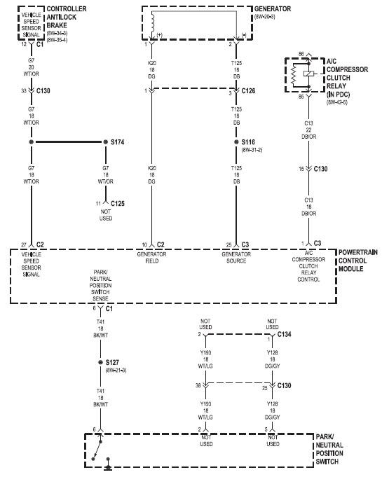
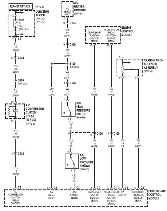
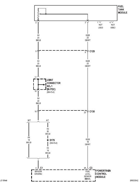
Two different control modules are used: The Powertrain Control Module (PCM), and the Engine Control Module (ECM). The ECM controls the fuel system. The PCM does not control the fuel system. The PCM’s main function is to control: the vehicle charging system, speed control system, transmission, air conditioning system and certain bussed messages. The PCM can adapt its programming to meet changing operating conditions. The PCM receives input signals from various switches and sensors. Based on these inputs, the PCM regulates various engine and vehicle operations through different system components. These components are referred to as PCM Outputs. The sensors and switches that provide inputs to the PCM are considere PCM Input
Inputs
-
A/C request (if equipped with factory A/C)
-
A/C select (if equipped with factory A/C)
-
Accelerator Pedal Position Sensor (APPS) output from ECM
-
Auto shutdown (ASD) relay sense
-
Battery temperature sensor
-
Battery voltage
-
Brake switch
-
CCD bus (+) circuits
-
CCD bus (-) circuits
-
Crankshaft Position Sensor (CKP) output from ECM
-
Data link connection for DRB scan tool
-
Fuel level sensor
-
Generator (battery voltage) output
-
Ignition sense
-
Output shaft speed sensor
-
Overdrive/override switch
-
Park/neutral switch (auto. trans. only)
-
Power ground
-
Sensor return
-
Signal ground
-
Speed control resume switch
-
Speed control set switch
-
Speed control on/off switch
-
Transmission governor pressure sensor
-
Transmission temperature sensor
-
Vehicle speed inputs from ABS or RWAL system
Outputs
After inputs are received by the PCM, certain sensors, switches and components are controlled or regulated by the PCM. These are considered PCM Outputs. These outputs are for:
-
A/C clutch relay and A/C clutch
-
Auto shutdown (ASD) relay
-
CCD bus (+/-) circuits for: speedometer, voltmeter, fuel gauge, oil pressure gauge/lamp, engine temp. gauge and
-
speed control warn. lamp
-
Data link connection for DRB scan tool
-
Five volt sensor supply
-
Generator field driver (-)
-
Generator field driver (+)
-
Generator lamp (if equipped)
-
Malfunction indicator lamp (Check engine lamp)
-
Overdrive warning lamp (if equipped)
-
Speed control vacuum solenoid
-
Speed control vent solenoid
-
Tachometer (if equipped)
-
Transmission convertor clutch circuit
-
Transmission 3–4 shift solenoid
-
Transmission relay
-
Transmission temperature lamp (if equipped)
-
Transmission variable force solenoid (governor sol.)
Wiring Diagrams


