


update: I am not longer providing any support beyond what is found in this Article. I don't have the time to work with this stuff anymore., but thankfully Quadzilla is up and running again, you can find them at www.quadzillapower.com
Hope This helped you guys out
Nick
Looking to buy a Quadzilla here is the links back to Quadzilla Power.
1998.5 to 2000 Dodge Ram Quadzilla Adrenaline $699.99
2001 Dodge Ram Quadzilla Adrenaline $699.99
2002 Dodge Ram Quadzilla Adrenaline $699.99

Tuners:
Adrenaline standard
The Quadzilla Adrenaline tuner, or Quad ADR, is a wiretap fueling , canbus fueling, and timing box for your 24v Cummins power turbo diesel in a Dodge ram application.. It is very customizable which makes it easy to tune for your specific needs. The Quadzilla Adrenaline or ADR will fuel to ~3500 RPM depending on the truck and the health of the Bosch VP44 injection pump for your Cummins power Truck.
Custom Tunes can be found in this article covering both the old Quadzilla tuning and the New Quadzilla V2 Tuning. along with information in regards to how to tune.
Base Tunes for Adrenaline and ZXT:
The base tunes provided by Quadzilla can be found HERE A huge thanks to Jigabop for hosting and various members for sharing their saved files.
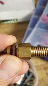
Model numbers:
ADR1000 98.5-00 model truck
ADR1001 2001 model truck
ADR1002 2002 model truck
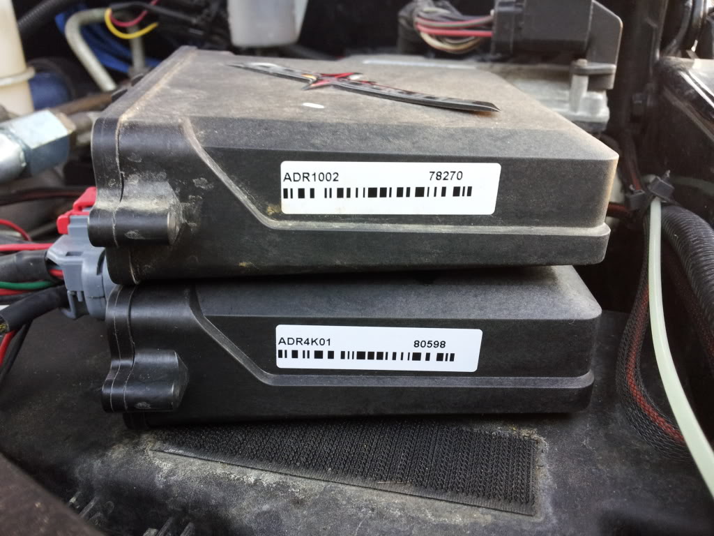
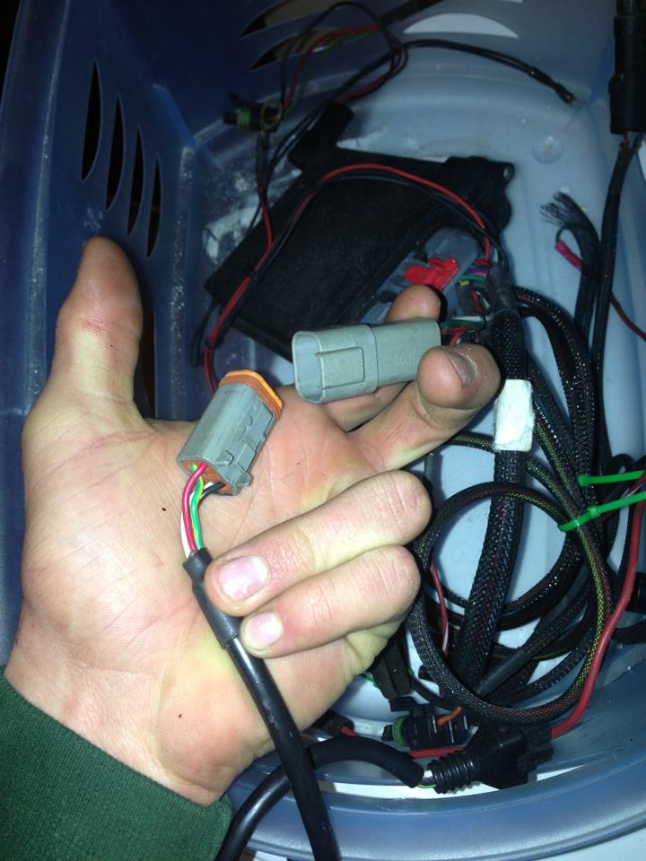
The Model number will be on the side of unit as seen above. The top tuner is a standard ADR for a 2002 model truck and the bottom is a 4k tuner for a 2001
Adrenaline 4k
ADR4k00 98.5-00 Model truck
ADR4k01 2001 Model truck
ADR4k02 2002 Model truck
The ADR 4k boxes allow the Revlimiter to be raised to ~4000 RPM. Think of this as a soft limit, not every truck will fuel to 4000 RPM as the VP44 has trouble at higher RPMS. Every truck will act different. The ADR 4k tuners are very well known for not being street friendly.
Again I am pretty sure that the only physical difference in the 4k tuner between the model years is the jumper inside. The wiring harness pigtails for the MAP and Canbus should be the only difference.
Adrenaline 4k VS Standard Adrenaline
This Thread covers the actual physical differences between the 4k box and the standard ADR. Please read the entire thread if you have any questions in regards to upgrading a Standard ADR to a 4K ADR. There is a lot of good information in that thread that I am not going to move over to this thread at this point.
***Please note that it is not possible to turn a standard ADR tuner into a 4k tuner without changing the internal parts. To my knowledge no one has tried yet.
***Don't load the 4k tune from the tune library on a ADR1000,ADR1001, or ADR1002 model
Boost Values reading Incorrectly
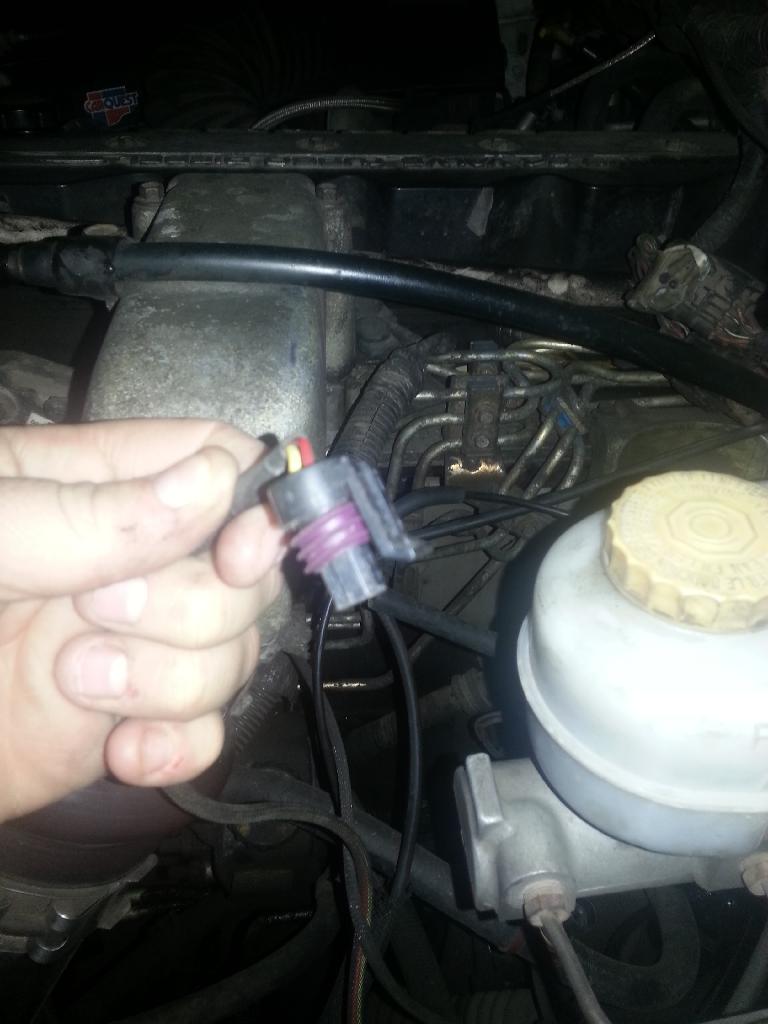
If your boost values are not reading correct you may have to remove or insert a jumper within the box. The only real difference I am aware of between the actual physical standard ADR tuner between the model years is the jumper within *Not the 4k vs standard ADR differences*. If the jumper is installed the MAP values will read correctly for the 01-02 years but not right for the 98.5-00 years. Taking the jumper off from within will make the 98.5-00 MAP values read correctly, but not 01-02. You can see the jumper circled in the picture below.
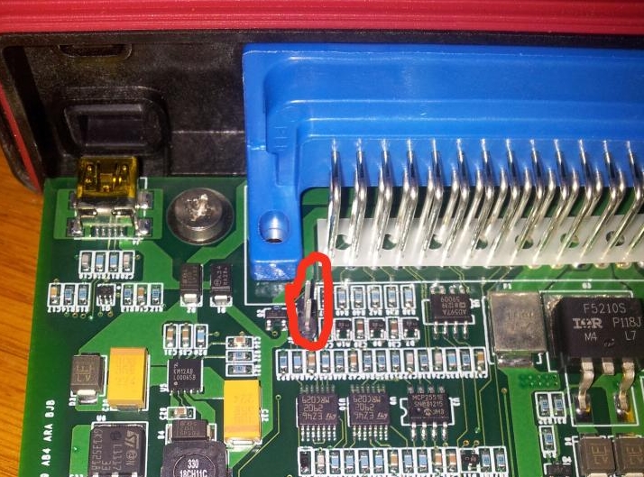
No Jumper installed 98.5-00
Jumper Installed: 01-02 years
** Sometime in Older adr boxes the jumper must be installed for 98.5-00 and not installed for 01-02
I have personally run a 01 unit on my 2000 without issues just by changing the internal jumper. Truck ran fine, tunes loaded fine.
The difference really comes with the wiring harness pigtails that shipped with the unit as explained below.
Harness
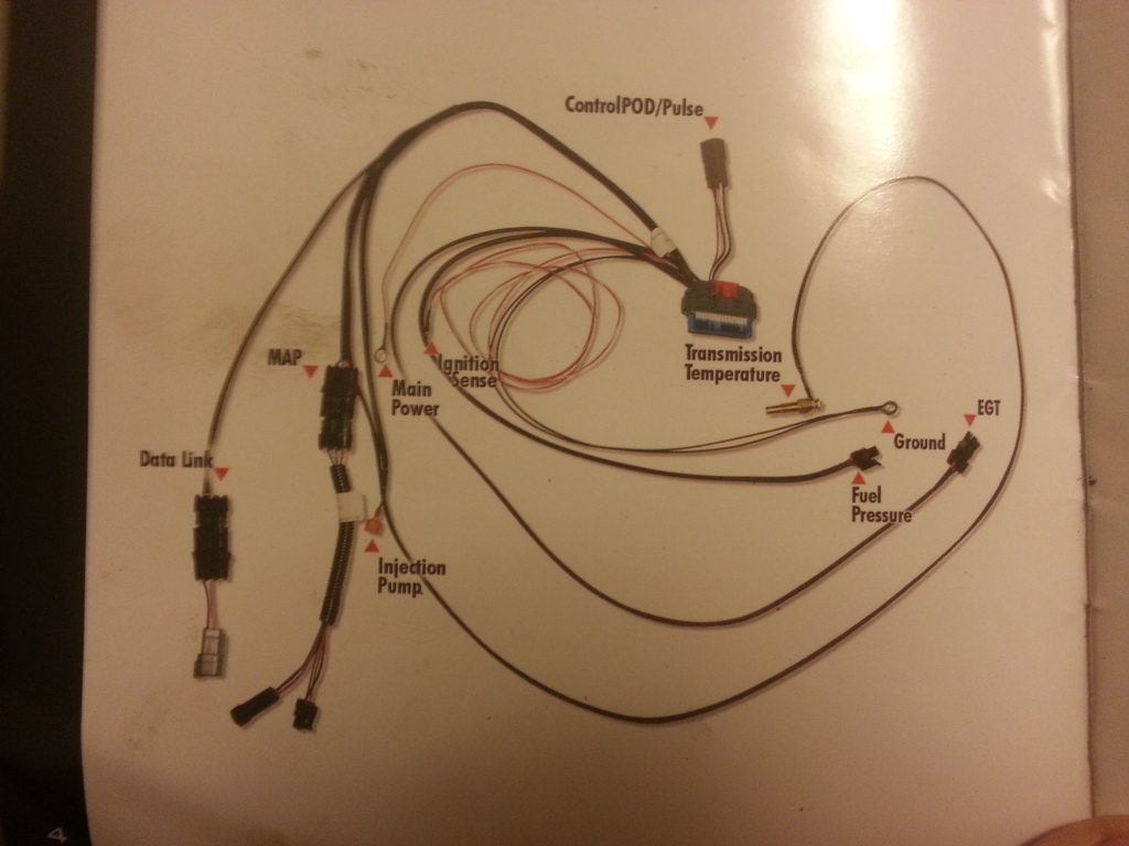
The Different model year ADR tuners use the same box, BUT a different harness pigtails for the different years.
Connectors
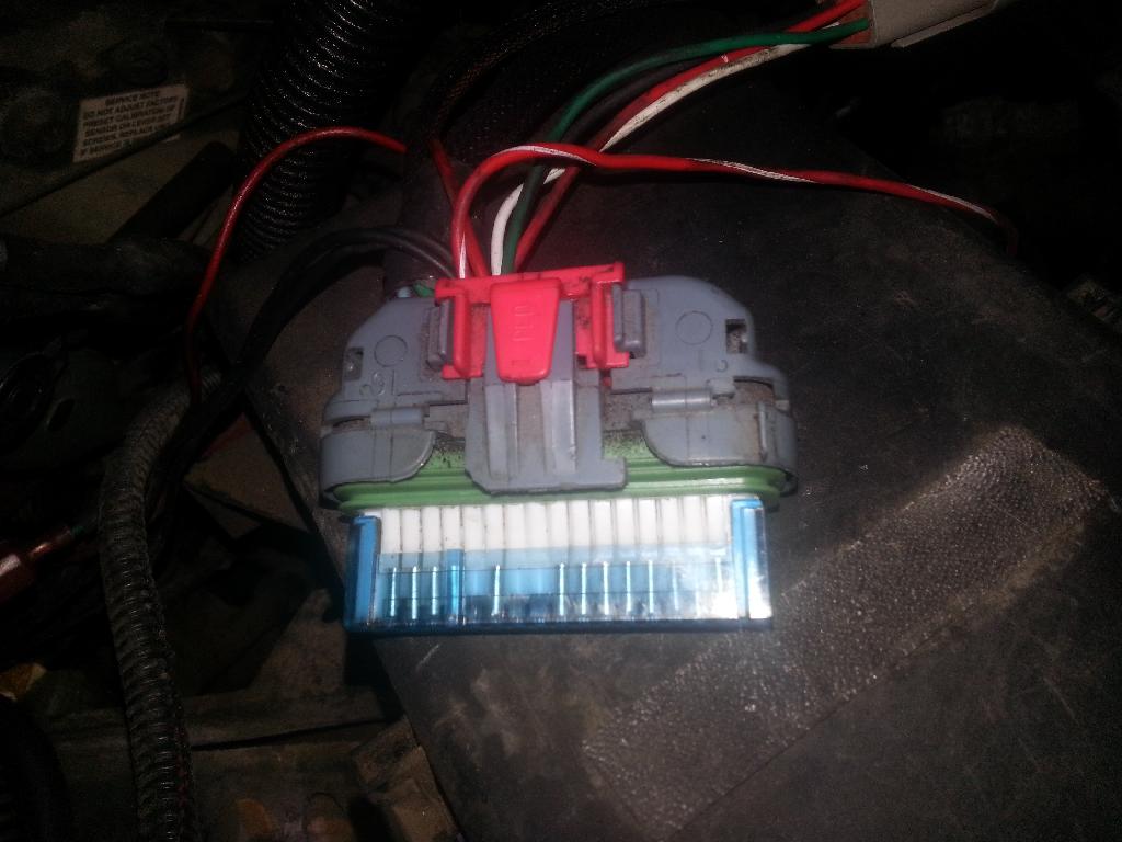
Main harness Connector
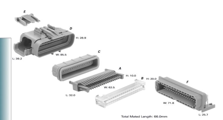
The main Harness Connector is a Delphi Connector. Information on it including part numbers for specfic parts can be found HERE Personally I order random parts like this from Mouser.
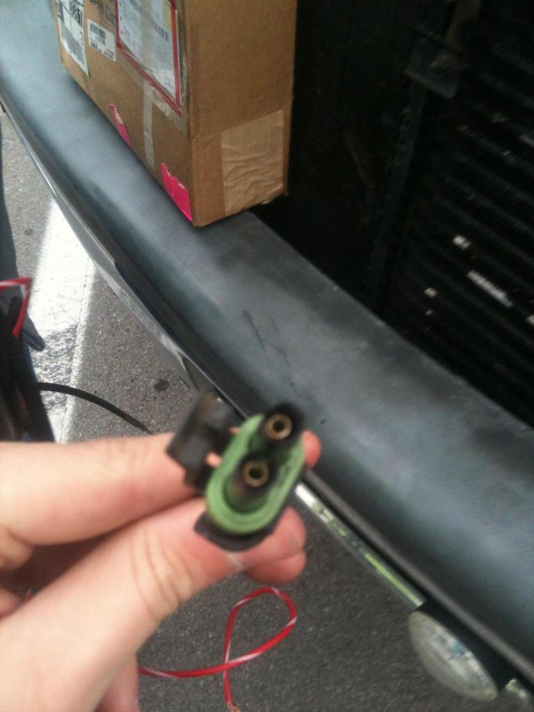
MAP
The ADR 1000 Uses a different MAP plug than the 01-02 style. I believe there is an adapter to convert from 00 style to 01-02 style, but it is very hard to come by. The 01 and 02 don't share the same MAP sensor pin layout but they use the same plug. There is a converter to use a 01 MAP to a 02 which I am pretty sure was included with the sale of ADR1001 and ADR1002 Tuners. This converter isn't as hard to find. You should be able to find this adapter from EDGE. The plugs are the same regardless of the of maker of the tuners.
MAP sensor connector for the 98.5-00 Model Year 3 pin round It's hard to see but it is too cold and too windy for me to want to mess with it now. It will look very similar to the Fuel pressure connector, but the MAP will have a pigtail on it and the Fuel pressure will not.
I believe the female MAP connector for the 98.5-00 years is a Delphi PN: 12065287
12065287 Delphi Connection Systems | Mouser
I believe the male MAP connector for the 98.5-00 years is a Delphi PN: 410027
http://www.casperselectronics.com/st...oducts_id=1524
MAP for the 01 3 pin flat
http://i879.photobucket.com/albums/ab360/me78569/Quadzilla/IMG_0535_zps240f198c.jpg
MAP for a 02 uses a 3 pin flat, but has a different pinout than the 01.
02 map sensors use the same plug with a different pin out on the non-ground wires. Some trucks have been moved to 01 map sensors so check to see what map you have.
Making your Own Map converter for the Quadzilla
You will want to buy the right MAP sensor connectors listed above for your year truck.
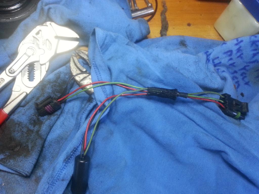
The wiring for the MAP converter is a little odd. This is due to the box doing boost fooling
Dark Green, or the wire C coming from goes to the ECM side of the pigtail
Green, or wire B goes to the MAP sensor side of the pigtail
Red, or wire A goes to both the ECM side of the pigtail and the MAP sensor side of the pigtail, just splice them together as shown.
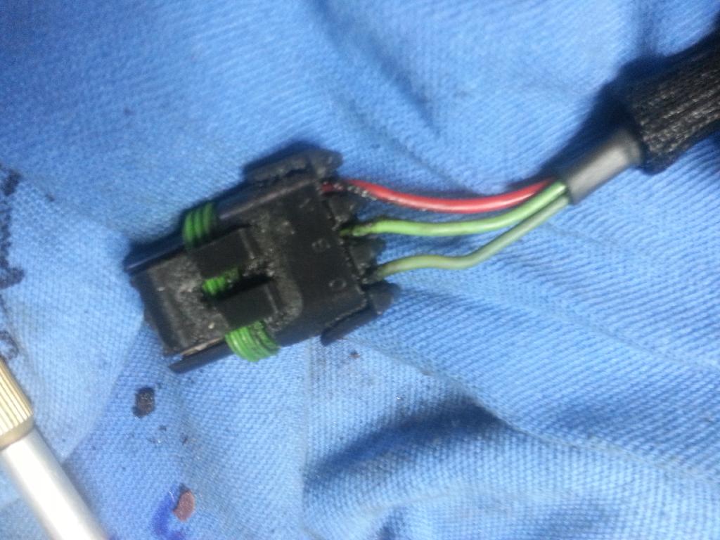
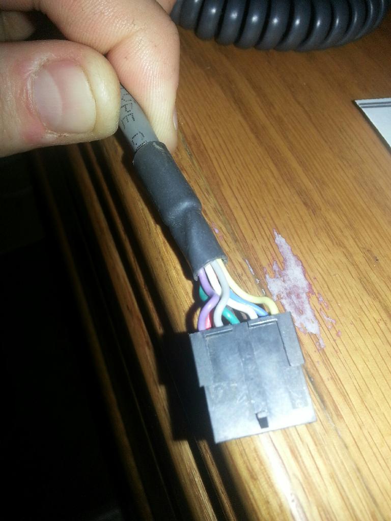
Here is the wiring for the MAP sensor side of the pigtail, Notice the clip on the top of the plug.
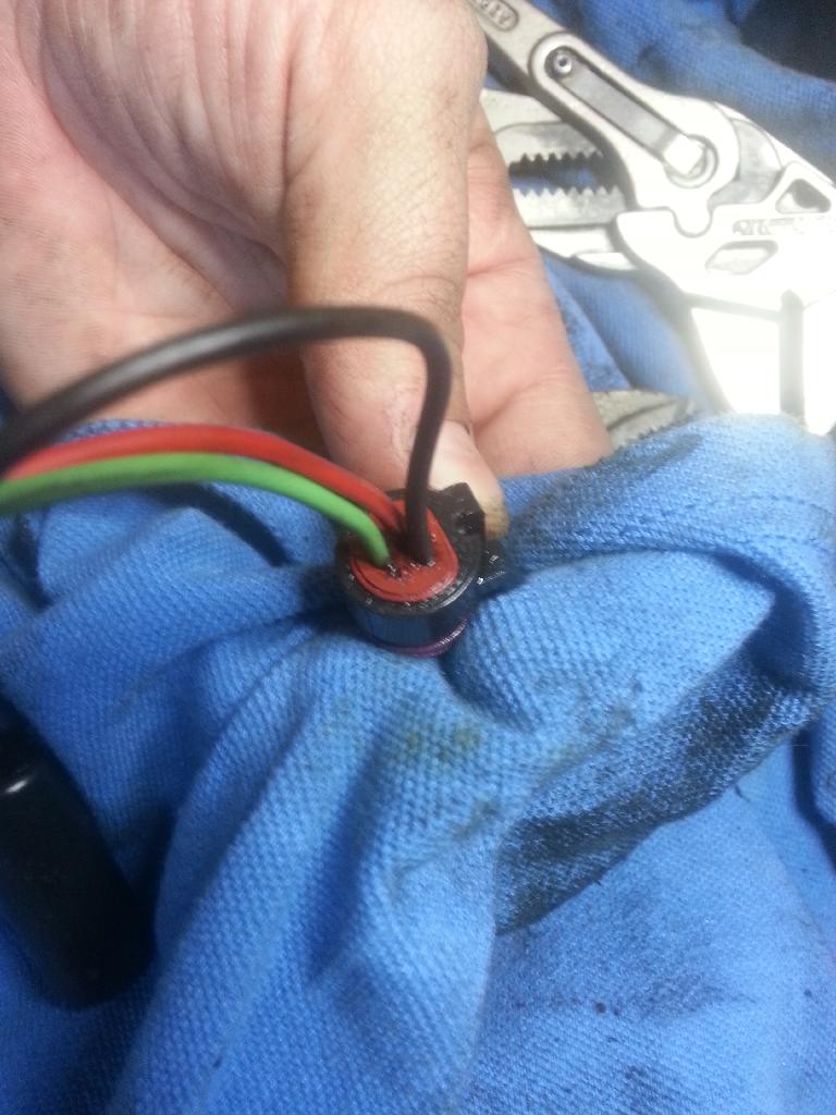
Here is the connector for the ECM side of the pigtail, notice the black and red on the top and green on the bottom.
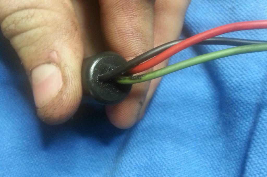
The Ground is shared between the female and male section
Canbus / Datalink
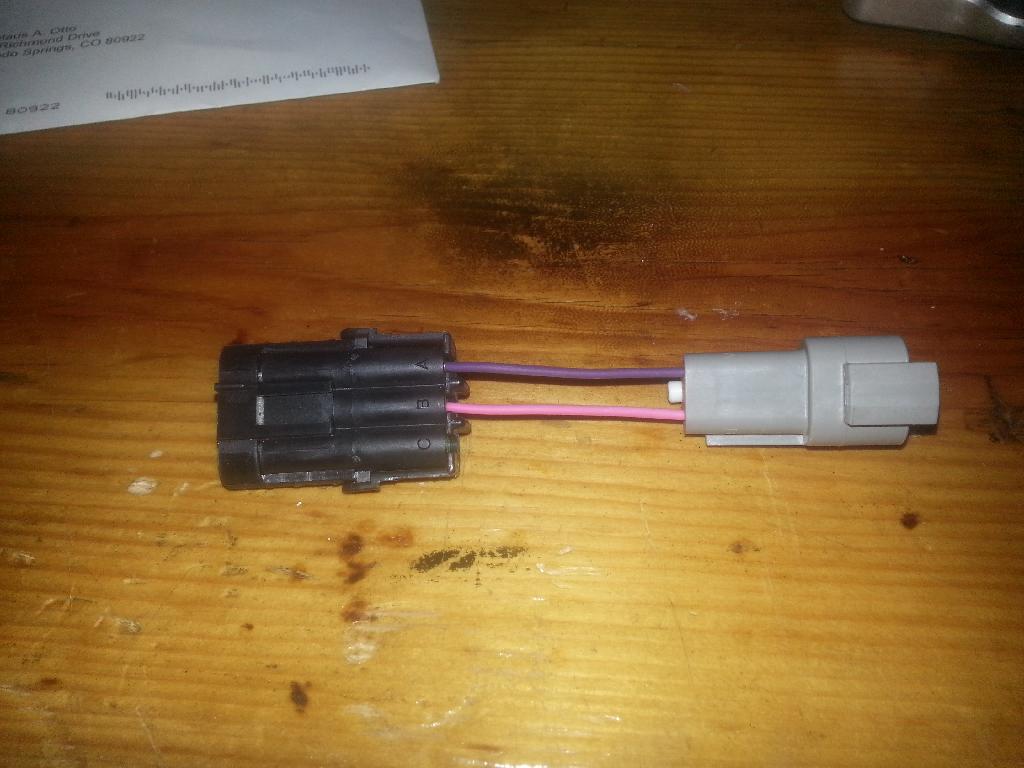
The Canbus/ Datalink also uses a different plug depending on the year, which there is an adapter for, I believe every ADR sold came with a Canbus adapter. Again this adapter should be sold by multiple companies as the plugs are the same regardless of the maker of the tuner. If you make your own just match the wiring as shown in the picture. Each plug is labeled A, B, and C
The flat 3 pin canbus/data plug is a Delphi plug.
Male connector assembly is PN: 12010717
Female connector assembly is PN: 12065287
the triangle data link is a DT04-3P.
You can make your own or look for on Ebay or Craigslist. They can typically be found for $25-$35
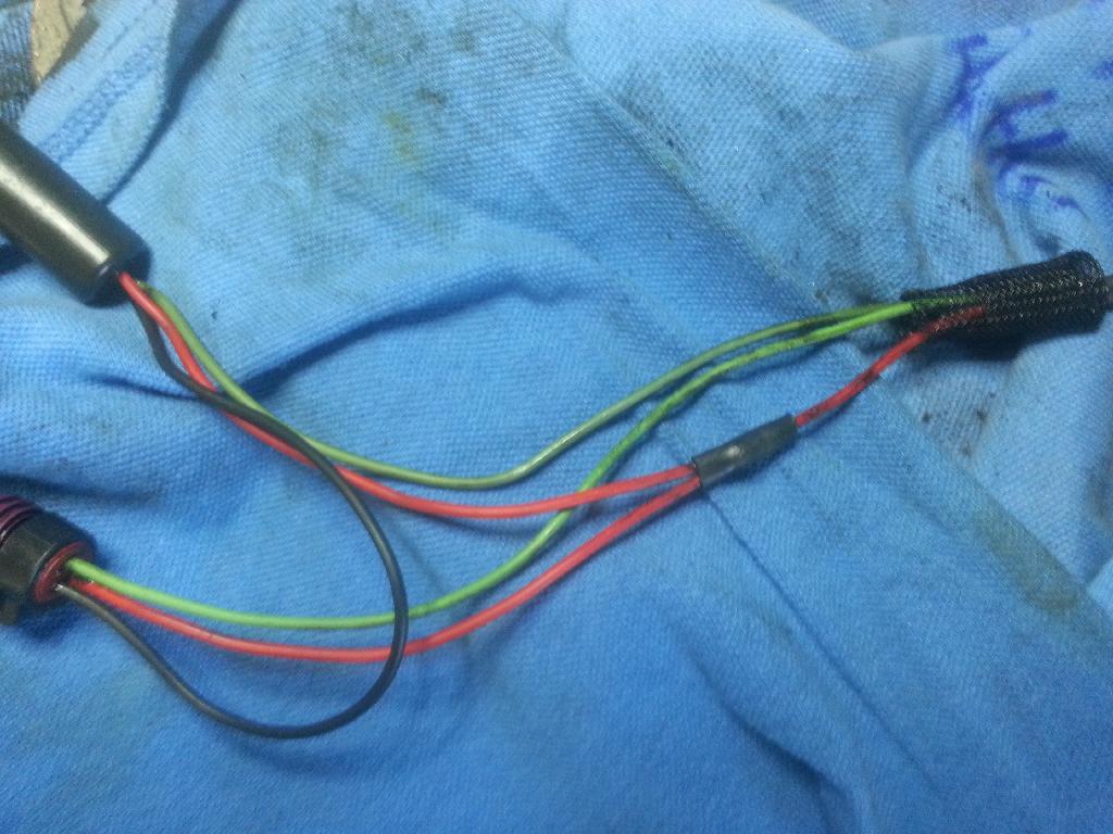
Fuel pressure
the Fuel pressure connector looks like this
very similar to the MAP but it is a single connector on the lead wires. Color for the wires are Red, Yellow, and black
I believe The FP uses a Delphi Connector also. PN: 12065287 12065287 Delphi Connection Systems | Mouser
To summarize the above information, The wiring harness connector pigtails are specific between the ADR1000 and ADR1001/2 tuners for the MAP sensor. If you have a 1999 year truck, but a ADR1002 tuner you can run it just by using a ADR1000 harness and changing the jumper setting within. The wiring harness Pigtails are what you need to match to you year truck. There are adapters out there, but it is easier to find the right harness. You can also splice the harness and use the OEM connector found at a multitude of online vendors.
Updating your Tune:
**DO NOT CONNECT THE MODULE TO THE COMPUTER UNTIL INSTRUCTED TO DO SO**
Windows 7 8 10
Windows Vista & Windows XP
This software has been designed to work with Windows XP and MOST Vista machines, and does not work on Macintosh. If you have a Vista computer and the update does not work, an error log called “QZError.log” will be automatically saved
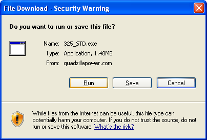
Begin the download process by clicking the “download” button associated with the tuning file you would like to use from the Quadzilla update web page.
Windows will ask you if you want to “run” or “save” the file.
If you would like to keep the tuning file on your computer for future use choose “save” otherwise click “run”. If you choose to save the file, you will have to specify where you would like to save the file on your computer. You can save it anywhere you like, although saving to the “desktop” allows for easy access.
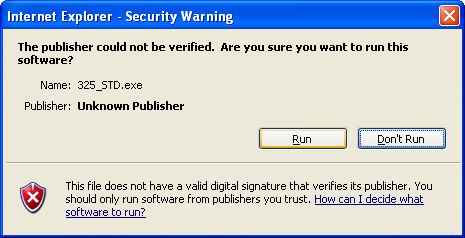
After the download is complete, Windows will ask if you would like to “run” the file. Select “run” to open the X2 flash software.
If this is not your first time to use the X2 Public Flasher, then you will not see the “Setup Wizard” load when the utility is started. Please skip to page 9.
If this is your first time to use the X2 Public Flasher utility, please follow the proceeding steps:
1. Begin by clicking “run” after the download is complete. This will start
the utility.
You should see the “Setup Wizard” if this is your first time to run this program.
This window will guide you through setting up the device drivers for your module.
Once the “Setup Wizard” completes, you will not see it on subsequent uses of the X2 Public Flasher.
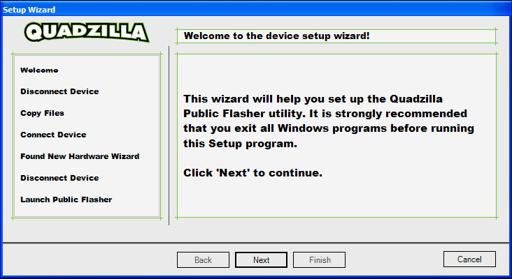
2. Click “Next” to allow the file copying process to begin.
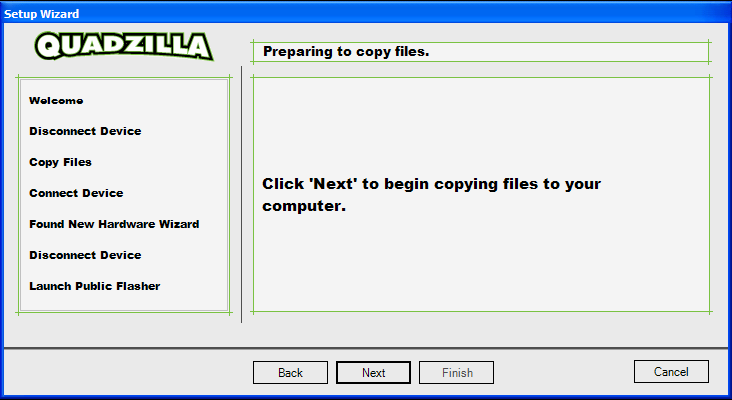
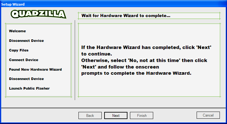
3. Once all files are copied to your computer, you will be prompted to complete the steps necessary for the Hardware Wizard to begin.
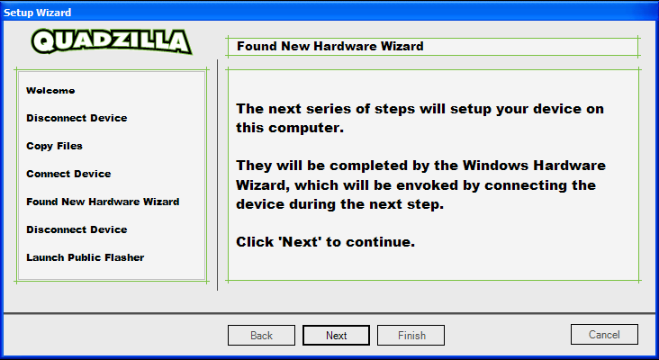
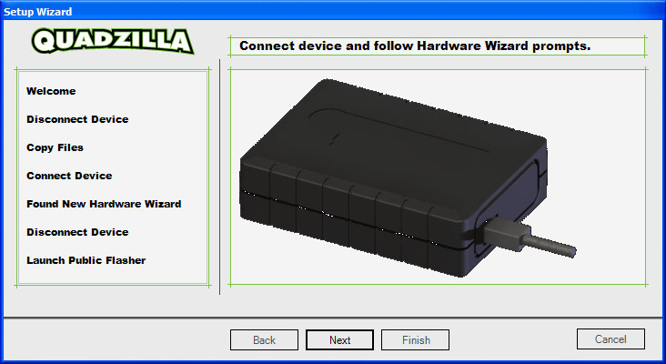
4.After you have read the displayed instructions on this step, click “Next” to continue. When you see the following screen, you will need to connect the module to the computer and click “Next” so that the “Hardware Wizard” may begin.
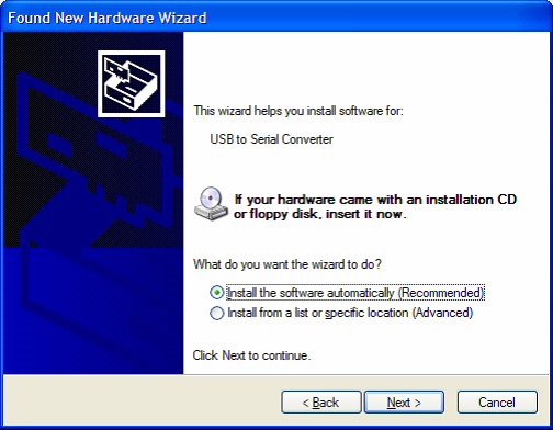
5. When you see the “Welcome to the Found New Hardware Wizard”, select “No,not this time” or “Install the software automatically (recommended)”,and click “Next”. Please be patient as the “Found New Hardware Wizard” may take several minutes before reaching the next screen, depending on the speed of your computer.
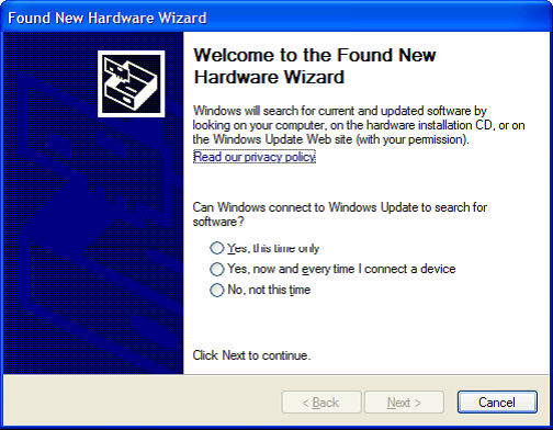
**If you do not see the “Found New Hardware Wizard” within a couple of minutes,
disconnect the module from the computer, wait one second, then reconnect it to the computer.**
6. Once you have reached the below screen, select “Install the software
automatically (Recommended)” and click “Next”.
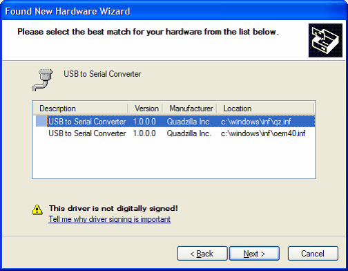
7. Select the driver with a “Location” ending with “qz.inf” and click “Next”.
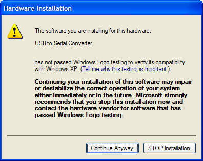
**Not all computer systems will display this message, if you do not see this screen simply go to the next step**
8.You will then see the following “Hardware Installation” screen, simply choose
“Continue Anyway”.
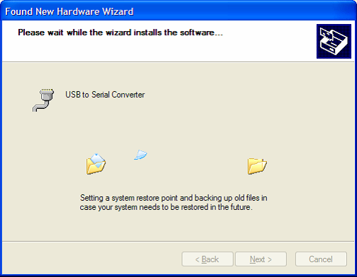
9. The “Found New Hardware Wizard” will then continue installing the necessary files to your computer.
If at some point around this step you get an error message that reads, “Files needed. The file usbser.sys on windows drive cabinet is needed” GO TO STEP 14 OF THESE INSTRUCTIONS TO READ ABOUT HOW TO PROCEED.
10. When you see the following “Cannot Start this Hardware” message click “Finish” and disconnect the module from the computer.
11. Once the “Hardware Wizard” completes, click “Next” to proceed with the setup.
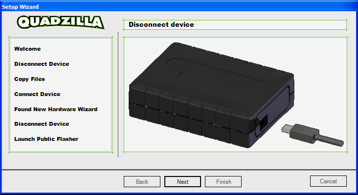
12. It is now time to disconnect the module from the computer.
Once you have disconnected the module from the computer, click “Next”.
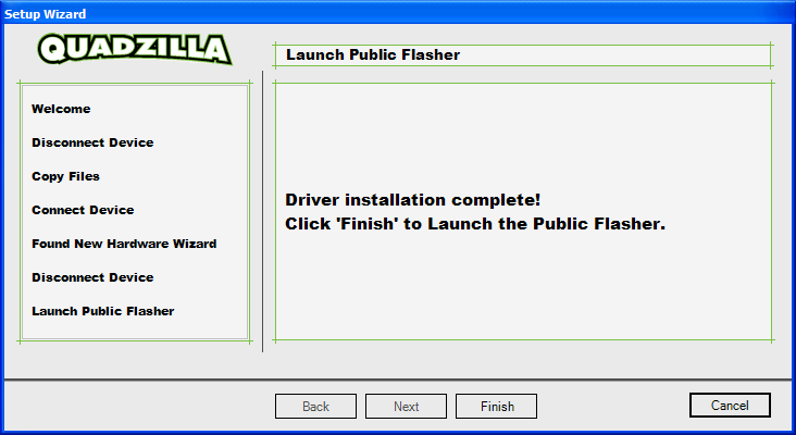
13. The following screen indicates the “Setup Wizard” has completed its tasks
You may now click “Finish” to launch the “X2 Public Flasher”.
14. (This step only applies if a “files needed” error was encountered)
A. Look at the error window that popped up saying that there are “files needed”. There should be a button that reads “BROWSE” click it.
B. Another window will pop up that will allow you to manually select the file. At the top of this window there should be a pull down menu, click the small arrow symbol pointing down, and choose the folder labeled “WINDOWS” .
C. In the “WINDOWS” folder scroll down until you see another folder that reads “system 32” and open it.
D. Within the “system32” folder there should be another folder labeled “drivers” , open it.
E. In the “drivers” folder there should be the file labeled “usbser.sys” , click on this file and click OK, the next to finish the hardware installation wizard.
F. Revert to back to step 10 to finish the installation wizard.
Loading a Tuning File to your Xzillaraider2, XZT+, M3, or Adrenaline Module
Before beginning, make sure you have the Microsoft .NET Framework installed on your computer. It may be freely downloaded from:
Updating your module is accomplished by following three easy steps:
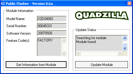
1. Start the X2 Public Flasher. Example:
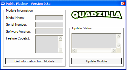
2. Click “Update Module” and connect your module to the computer within ten seconds.
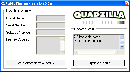
3. You can click “Get Information from Module” after programming to verify the tuning file has successfully been installed. Check the feature code and make sure it corresponds to the file that you desired to use.
At this point you are ready to reinstall the module on your truck and enjoy your new tunes!
Xzt
http://i879.photobucket.com/albums/ab360/me78569/Quadzilla/XZT-plus_zpsa7a1d9ed.jpg
The Xzt is a canbus and timing box. It connects to the Canbus for fueling and the MAP sensor for boost fooling and fueling based upon boost. It does the same hp as other Canbus tuners or ~65hp and ~125ft/lb along with a timing increase. HP numbers are pretty relative. It should be very similar to the Edge EZ
I am not an expert on the XZT but I am pretty sure you need the correct XZT for your year truck/MAP sensor type. Again 98.5-00 uses the 3 pin round plug, 01 uses a 3 pin flat connector and 2002 uses a 3 pin flat connector with a different pin layout.
Tunes for the XZT can be found on Jigabops hosted site found in numerous places in this post.
Screens:
PV2
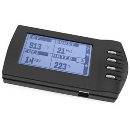
If you want to update your PV2 please ensure that you are running the update from a Windows XP machine. If you run the update file from a windows 7 machine it will make your PV2 useless. The update can be found on Jigabops tune download site within the complete tune zip.
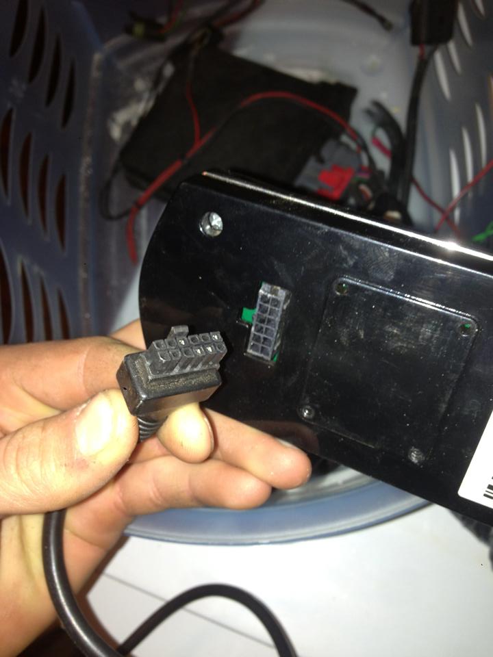
Making your own PV2 Cable
Big thanks to Cumminsdog and Tdoorn28 for posting pictures and PN for the needed parts.
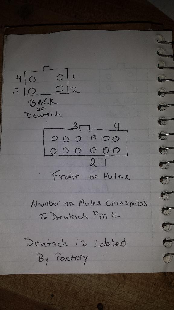
The 12 pin molex connector on the screen side of the wiring harness THIS is the male part! Again the picture is wrong but everything else should be right.
43020-1201 - MOLEX - PLUG & SOCKET CONNECTOR, PLUG, 12POS, 3MM | Newark element14 US [URL=http://s879.photobucket.com/user/me78569/media/Quadzilla/1510561_618106761586980_1710185498_n_zpsec810060.j pg.html]
Here is the wiring pinout for the cable
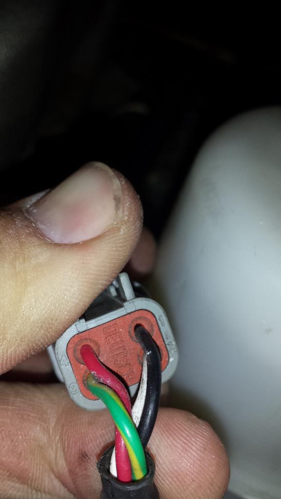
The 4 pin connector on the ADR harness side is a Duestch connector. It can be found HERE
PN DT06-4S
Ensure the wire orientation match that in this picture for the plug.
PV1
PV1 Doesn't change power levels
If your PV1 won't change power levels or accept custom tuning you likely need to run the PV1 upgrade program hosted on Jigabops Quadzilla site. It is VERY important to run the upgrade from a single core Windows XP 32bit machine. I ran the upgrade 10+ times from a single core 32bit windows 7 machine and always ended up with a PV1 that wouldn't change power levels. Once I ran it from a Windows XP machine it started working again.
Flashing PV1 and PV2 screens from a Windows 7 Machine ***May or May Not Work***
The following steps allow you to upgrade/flash the PV1/2 using a Windows 7 machine provided it support Windows XP mode
http://windows.microsoft.com/en-us/w...e-in-windows-7
I will help as much as I can with this part, but you will have to research installing this on your own. It is possible as I have done it on my personal 64 bit windows 7 machine for one VP! screen, but for another it did not work. I would recommend using a XP machine EVERYTIME, but if you cannot for one reason or another xp mode may work
You must have windows 7 professional, Enterprise, or Ultimate. Your computer must also support CPU virtualization.
You will need to download and install
Windows Virtual PC
http://www.microsoft.com/en-us/downl...s.aspx?id=3702
And XP mode
http://windows.microsoft.com/en-us/w...e-in-windows-7
Once those are both downloaded you simply start the virtual windows xp then download and install Windows Framework 3.5 ( again I will try to help but installing Framework is your responsibility). Finally run the commander app with the PV1/2 plugged in, disregard when it says to unplug. Since it is a virtual environment the plugging in of the pulse is handled by forwarding that USB through the main machine, which you enable in the next step.
Install the quadzilla drivers from the installer. once the drivers have been installed and the update program prompts you to plug in the PV1/2 then you enable the usb device, by clicking USB on the top menu bar and selecing the Pulse pv1/2.
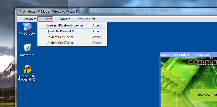
The pulse will show up and the windows pop up to install drivers will come up, This might take up to a minute for the usb to be patches through to the XP mode. Select install drivers automatically then click next. Click OK when the warning appears. When it finishes the install process you can click update now within the Quadzilla flasher program.
Once the Quadzilla finishes updating your power up and down buttons should work again.
Making your own PV1 Cable
The cable for the PV1 is very similar to the PV2, but the screen side is actually soldiered to the board instead of a nice Molex connector.
White: PAD 20
Black: PAD 21
Green: PAD 9
Red: PAD 12
These numbers were taken from my Commander screen which I am pretty sure is the same as a pv1 board. Take note of the spacing on the board if you do this yourself. Verify that my numbers match yours.
The ADR side of the cable is a Duestch connector. It can be found HERE
PN DT06-4S Ensure the wire orientation match that in this picture for the plug.
Fixing your PV1 buttons
The buttons on the PV1 are known for not working well. They can stick, not read etc. Here is a good write-up on how to install buttons for cheap. Very easy to do, works much better than the standard setup.
Pulse Monitor Modification (no more bad buttons!)
Big thanks to dknaks for this write-up
Specs are pretty basic, 5mmx5mm should work. You want to make sure the switch is momentary.
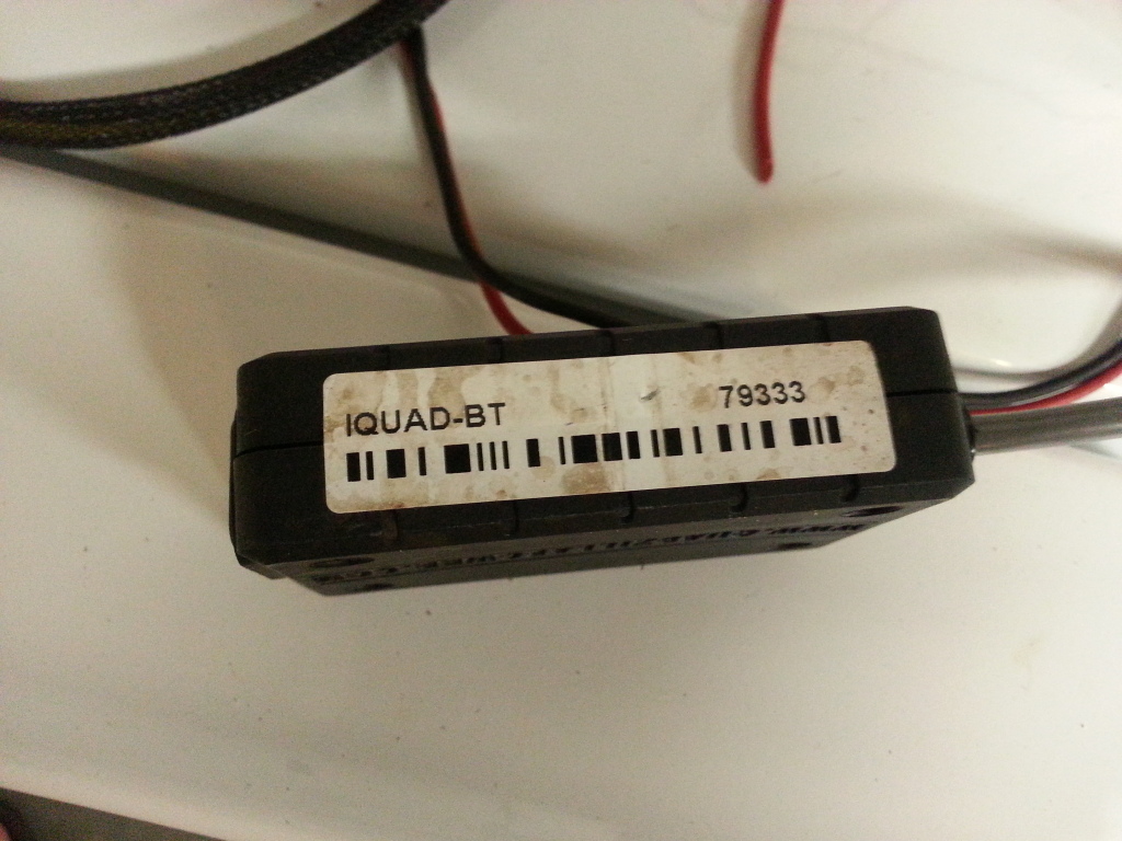
All iquad bluetooth modules share the same PN so it is fair to assume that the bluetooth module can be from any year.
The Iquad for Bluetooth is for Android only.
Converting PV Screens from other model years
PV2
From a purely speculation shot in the dark I will say that it MIGHT be possible to flash a different model year PV2 to work with the 2nd gen adr1000/1001/1002 boxes. From what I have seen with the PV1 screens I don't think Quad built the units with differences in the screens between the years. No one has tried that I am aware of using a PV2. I am more than willing to try if someone would provide me with a PV2.
****Again this is at your own risk****
PV1
See the below in regards to converting a Scout PV1 screen in the a working 2nd gen PV1. I am more than willing to try with other PV1's but again it is at your own risk.
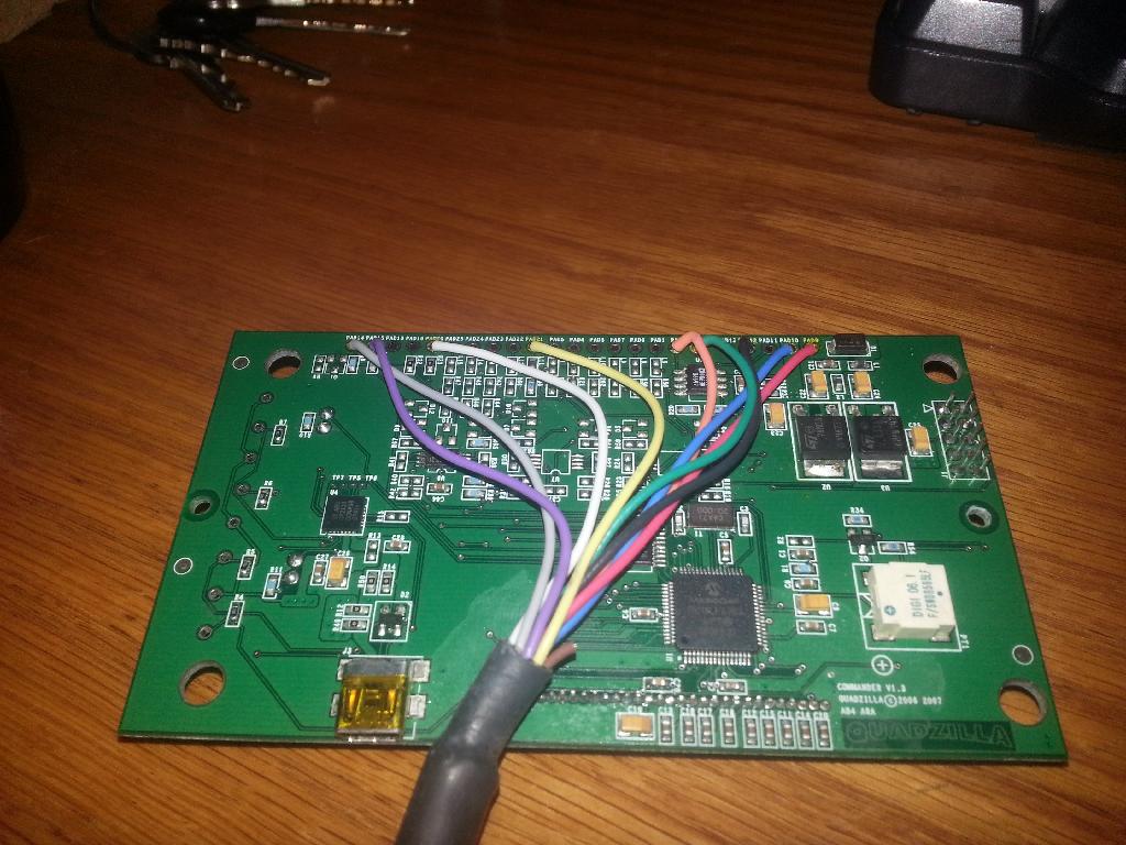
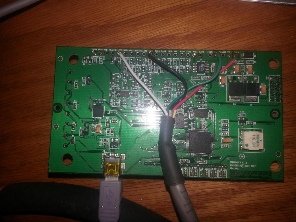
Converting a Commander/Scout screen into working with ADR
To the best of my knowledge on the subject, the commander screen and scout screens are both early PV1 screens. I personally have a Scout screen that a friend had for his 2003 dodge SMS1002. Inside the board states it is a commander v1.3, but when you plug it into the computer the driver that is shown is for a PV1.
However the tuner side of the cable is a 10 pin molex.
Using an XP machine I have loaded the PV1 update found on Jigabops hosted site. The Commander screen took the update fine and now has power levels and custom tuning as a setting.
***Very important to note that you need an XP machine to run the PV1 or PV2 update that is hosted by Jigabop. If you run the update on a windows 7 machine or vista (I think) you will very likely ruin your PV screen. Seeing as we don't have the original firmware for them I don't know if we can fix it. You may be able to rerun the update from an XP and fix the issue, but I am not sure.
I was able to soldier the correct wires into place on the board of my old commander screen to match the wiring from other PV1 screens
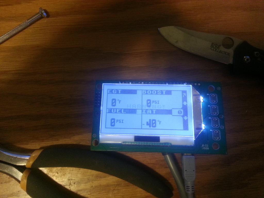
Here it is working with the PV1 ADR software
Sensors
EGT Probe
The Probe looks like this
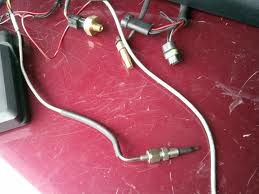
The connector on the harness looks like this.
Also
any K type thermocoupler will work with the Quadzilla. Cumminsdog was using an Isspro thermocoupler for ever with his. Again, any brand K-Type will work.
DAP also sells one. Link is HERE
Something like THIS
Fuel Pressure Sender
Isspro pressure sensors are supposed to work with the quadzilla. People have said they have in the past (actually tried it) and DAP told cumminsdog they were Isspro sensors.
DAP site link to the Fuel pressure sender HERE
The Issopro FP sender is PN: R89141, but I suggest contacting Jkidd at DAP first since they have verified that the part they sell works with the Quadzilla.
Transmission Temp Sender
The Quadzilla tranny temp sender is a Datcon 02022-00 Temp sensor. You can fine one HERE
Other temp sensors may work, but I would stick with the part above as it matches the PN# on the Quadzilla Sender.
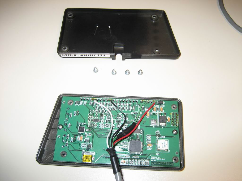
So you jumped your truck without unplugging the ADR tuner?
It is very important that you UNPLUG your Quadzilla tuner before jumping you truck. I can almost promise you that if you jump your truck without removing your Quadzilla tuner it will ruin your tuner. Typically after this happens the inside of your Quadzilla tuner will look like this.

The big White thingy ( technical term for resistor) is a 1 OHM 10w Resistor with a %5 tolerance made by xicon PN: 280-CR10-1.0-rc. You can replace it and other burnt parts to try and fix the issue, or Ask/bribe ED to try and fix it for you.
Mouser has them 280-CR10-1.0-RC Xicon | Mouser
The Mosfet has a PN of IRF5210SPBF
The thread having to do with Quadzilla stuff is HERE
Windows Vista Unhandled Exception Error.doc
If you find this helpful throw a donation my way. %95 of the things I do in regards to Quadzilla are to support the community and I receive no payment for the work.
Thanks
- Me78569
![]()
-
 1
1
-
 2
2
There are no reviews to display.