


Mopar1973Man.Com High Idle / MPG Fooler Overhead Console Installation
Ed Grafton sent me a Mopar1973Man High Idle switch for me to install into my overhead console, and do a write-up on it This is for guys that have no where else to put it due to too many gauges, or in the rare case like Jigabop who has too many options
Ed Grafton extended the length of the wiring to allow for the wires to be run from the overhead console, under the headliner, down the A pillar, and into the engine bay. Whole install took about 2 hours.
Tools And Supplies Needed
- Drill
- 2 1/8" whole saw
- Smaller drill bit to drill the center ( 1/4" - 3/8" something small to ensure the center hole is in the right position)
- Center Punch
- Straight Edge/Ruler 1/16"
- X Acto Knife
- Wire cutters/Strippers
- Soldering Iron
- Heat Shrink
- Lighter
- Phillips Screw driver
- Super glue or strong glue of choice
- Zip Ties
First thing you need to do is remove and unplug the overhead console. Do this by opening up the Garage Door Opener holder. You will see two clips that hold it onto the roof ( near the front). While pressing the clips pull down the front and slide it back.
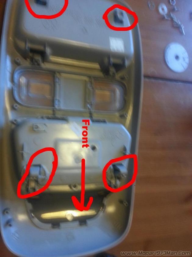
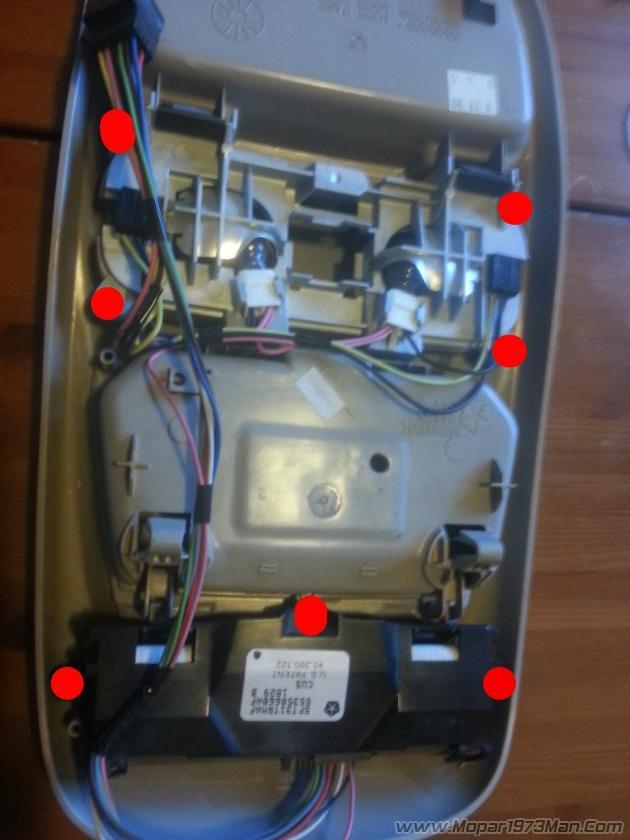
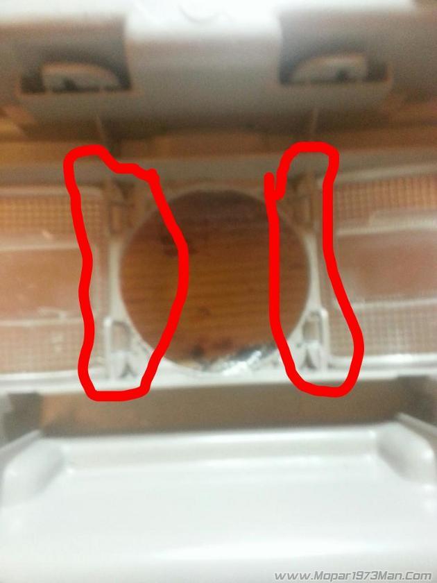
Next you need to remove the wiring and computer. Remote the Phillips screws hold in the lights (x4) and the Phillips screws holding in the Computer (x3) ****Notice the hole between the lights, this is where Mopar1973Man's High Idle wiring harness will be feed through. There is plenty of room between the console and the roof.
Remove the faceplate from the Mopar1973Man High Idle Switch. Do this by removing the set screen in the knob and pulling the knob off. Remove the retaining nut and spacer. You will need to reinstall this later in the reverse order to take care to remember how it dissembled so you can reassemble it.
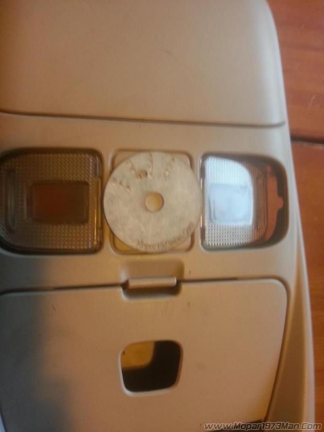
Just looking at the Overhead Console you can see it fits about perfect right between the lights. That being said it is easy to see that if you don't measure the center of the lights you will mess up and break your lights and end up with an off center hole
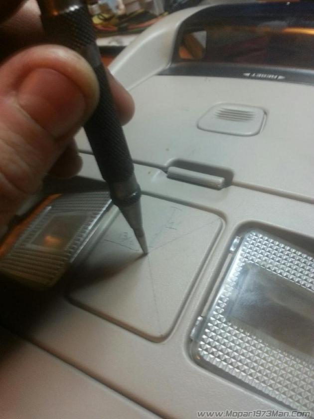
Measurements you want for the center of the plate is 1" vertical and 13/16" horizontal 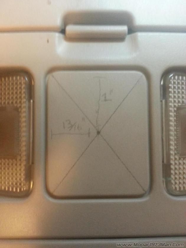
From the corners draw lines to find the center then verify with the above measurements. Measure and measure again.
User a Center Punch to set the middle for the drill bit. ENSURE that you are perfectly centered. If this center is not perfect your faceplate WILL NOT FIT.
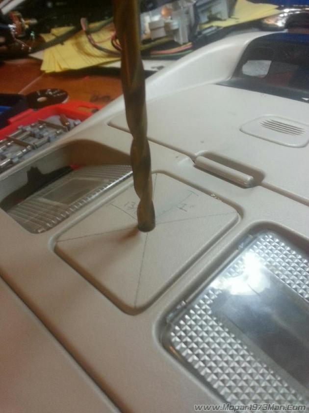
After using the Center Punch, place the drill bit in the center to set the center hole for the hole saw. Again ensure that the drill is set perfectly in the middle BEFORE drilling.
Next use the 2 1/8" Hole saw to cut out a circle for the faceplate to sit in. 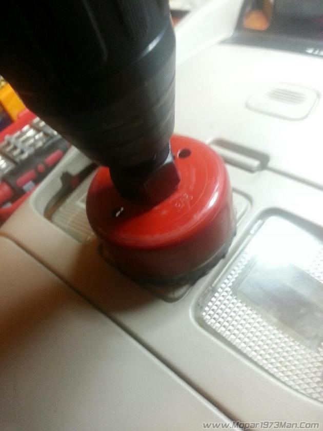
Drill slowly and stop as often as needed to reduce the amount of heat build up to prevent the plastic from melting too much.
Verify that the hole you are cutting fits between the clear lens for the lights.
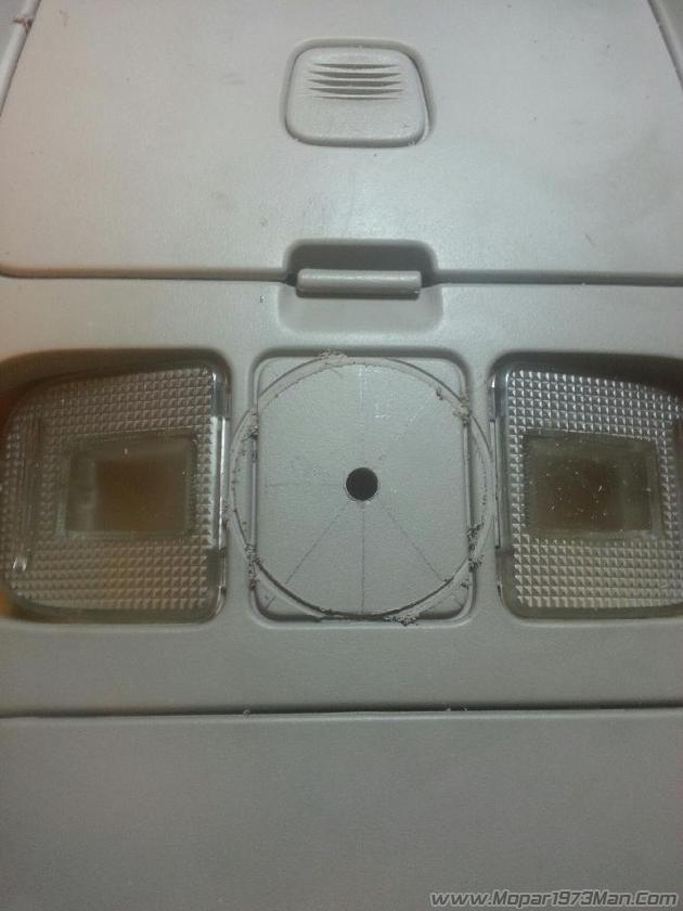
Again it will be close, but it does fit. Above all take your time cutting the hole out. The slower you do it the better the end result will be. The plastic is bound to melt some, but you can take care of this with the help of an xacto knife.
Once the hole is cut flip over the overhead console and verify that the clip section for the lens is intact. If you notice any breaks glue them back together. You may need to remove the lens to ensure you don't loose the functionality of the button press lights by gluing them shut.
Using your faceplate and X-acto knife fit the faceplate into the cut hole. You may need to cut out some melted plastic etc to get the faceplate to fit good. Test the movement of the lens once the gauge is test fitted. Cut overhead console as needed to make the lens work.
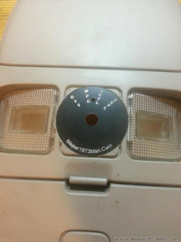
Once you are satisfied with the fitment/position of the faceplate glue it into place in the console. I choose to have the LED towards the back of the truck, but you can rotate the faceplate until it is in the position of your choosing. Glue from the back in a few locations slowly to ensure that no glue seeps to the front of the faceplate. Once the glue has dried then install the switch assembly into the faceplate in the reverse order of which you disassembled it. You will have to test the knob position, Far left is the off position. Once you have aligned the switch assembly tighten down the retaining nut that holds the faceplate. Reinstall the knob and verify again the turning the knob all the way counter-clockwise makes the knob point to the off position.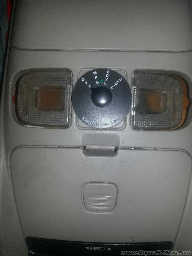
Next reinstall the lights and computer by feeding Mopar1973Man High Idle wires through the OEM lights and reinstalling the Phillips screws in the reverse order of the above. Take your time when reinstalling to ensure that the harness fits and the lights click again when you press the lights. It will take a little work to get everything fitting good, but you will not need to cut anything on the light and button assembly. Gently bend Mopar1973Man's High Idle harness to contort in the same place as the OEM wires. 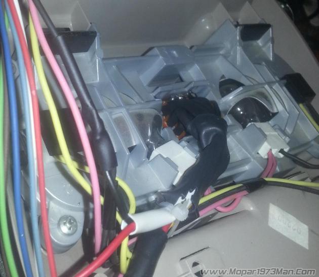
Next you need to supply power to the LED light. Thankfully there is 12v power already in the overhead console. The pink wire coming off the plug is 12v and the black wire next to it is ground. The pink wire is a keyed power wire, the yellow wire is a power that is supplied based upon doors open and interior lights.
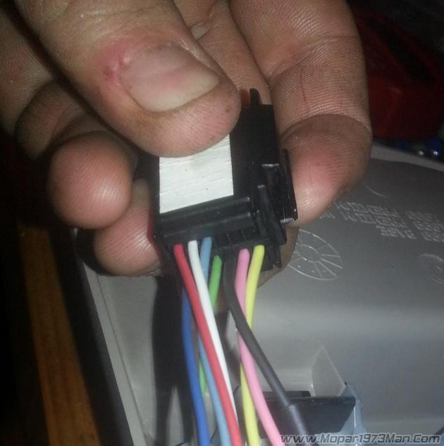
Cut the Black and Pink wire with enough length to install heat shrink on the end. I cut them about 2" from the OEM plug. Strip the red and black wire that are together in the white conduit. Ensure that you DON'T cut the wires that go to the OEM plugs for ECT and IAT. There will be 4 wires in the harness that goes to the engine and 2 wires in the harness that you are cutting. Pre-install the heatshrink wrap onto the plug side of the cut wires. Solder together the cut pink wires and the red wire in Mopar1973Man's High Idle harness. Then Solder together the cut black wires and the black wire in Mopar1973Man's High Idle harness. Using a lighter heat up the heat shrink wrap to seal your solder splice. Use a zip tie to hold the wires together. Test the led in the switch by plugging the OEM connection and turning the High idle switch to any position. If it doesn't work use a multimeter to test for power to the OEM connector.
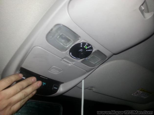
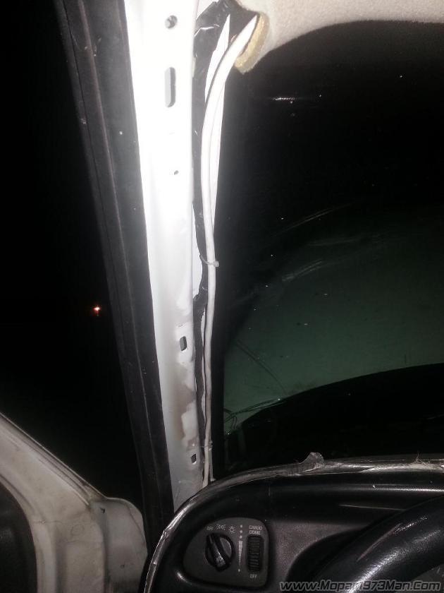
Next remove your sun vizor by removing the 4 Phillips screws holding it to the roof. Feed the Mopar1973Man's High Idle ECT/IAT harness under the headliner by Gently pulling it down. It doesn't take much. Once you feed it through the console hole in the headliner you can pull it towards the A pillar. There is plenty of room for the harness to run between the window and the front of the headliner. You can slip it under the headliner easily. The A pillar cover will pull off by just popping it out. Use zip ties to the hold Mopar1973Man's High Idle harness to the OEM wiring running down the A pillar.
Route the wiring through the dash and through the firewall into the Engine bay. Once at this point the install is the same as the other Types of installs for Mopar1973Man's High Idle switch.
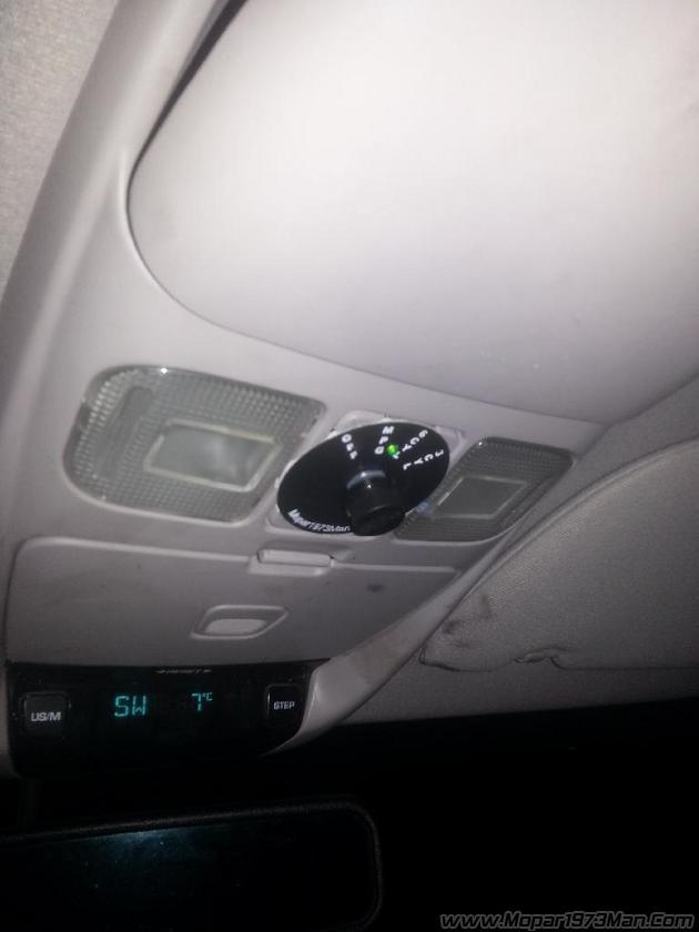
You will end up with something that looks like this.
There are no reviews to display.