


I decided to go through the trouble of installing a Momentary switch in the gear select arm. A Momentary switch means that it will only connect the circuit if the button is pressed. As soon as you release the button the circuit closes. IE: Pressing it will complete the Ground and trigger the Torque Converter to Lockup, as soon as you release the button the Torque converter lockup will release. This fixed the issue of forgetting that the switch was on when coming to a stop. I found that in the cases where I wanted to use the lockup switch I was already using my right hand to shift down or disable OD. It was only natural to think that a lockup switch on the Gear Selector would be nice.
This DIY is not for how to connect the lockup switch, You can see how to do that by clicking here.
Sorry for the blurry pictures.
You can use any switch you like, so long as it fits. The switch I used was 1 Black Momentary Off on Push Button Horn Switch | eBay
Your switch should be no deeper than ~1/2"
This will require taking the truck out of park to adjust the shifter, so ENSURE YOU APPLY THE EBRAKE AND CHALK THE WHEELS BEFORE YOU START.
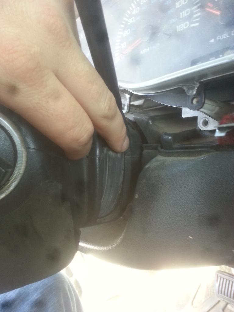
First thing to do is remove the gear select arm. To do so, remove the Dash Bezel, and drivers kick panel. The kick Panel is held on using 2 phillips head screws on the bottom of the panel and pinned into the top. Unscrew the phillips heads and pull the kick panel directly towards the seat. It should "pop" off without much issue. the dash bezel is just press fitted, I think ( my bezel has been gone so long I don't honestly remember.
Once the Kick panel is removed you need to disconnect the OD wires from the steering column. Thankfully dodge put a connection right there to do so 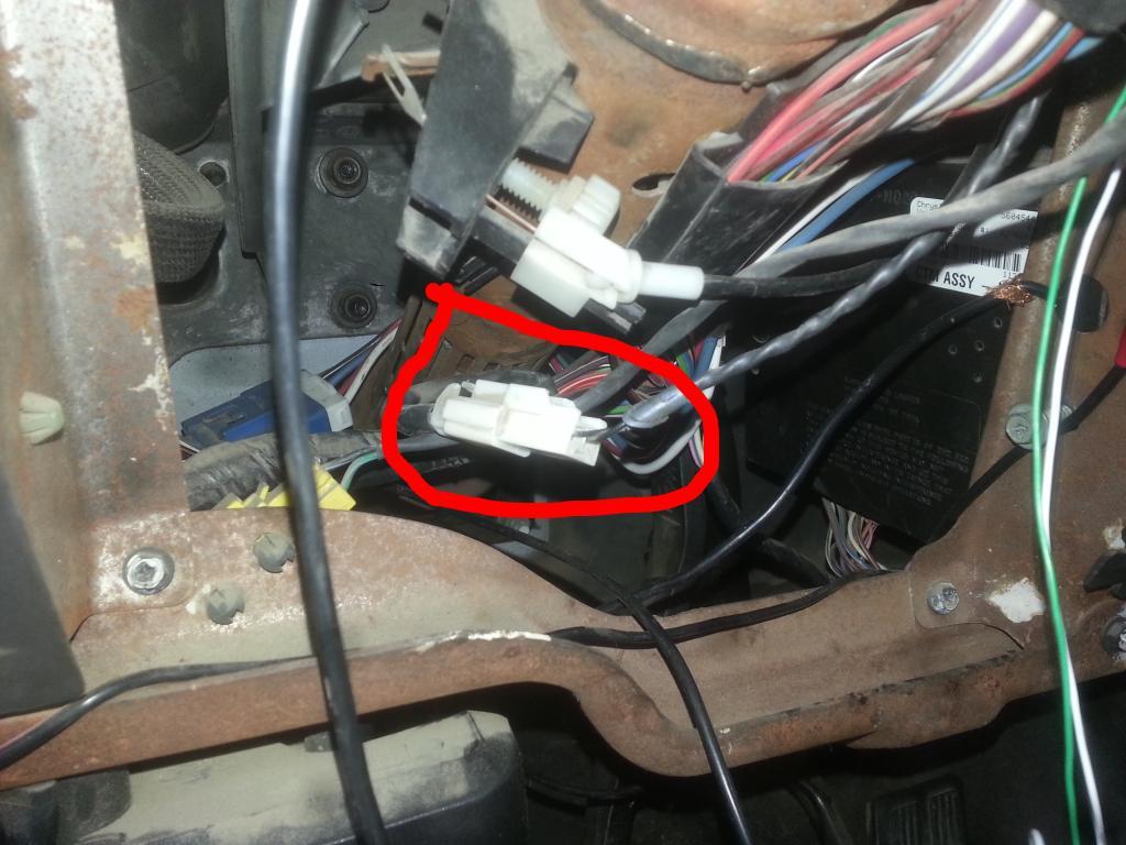
It should be attached to the bottom of the column itself. Disconnect the switch and let it hang.
Next you will need to use a t-20 torx driver to remove the bots under the steering shaft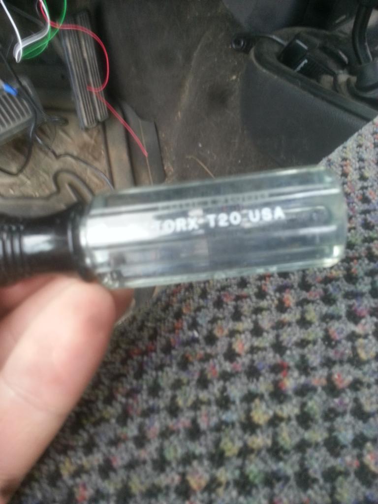
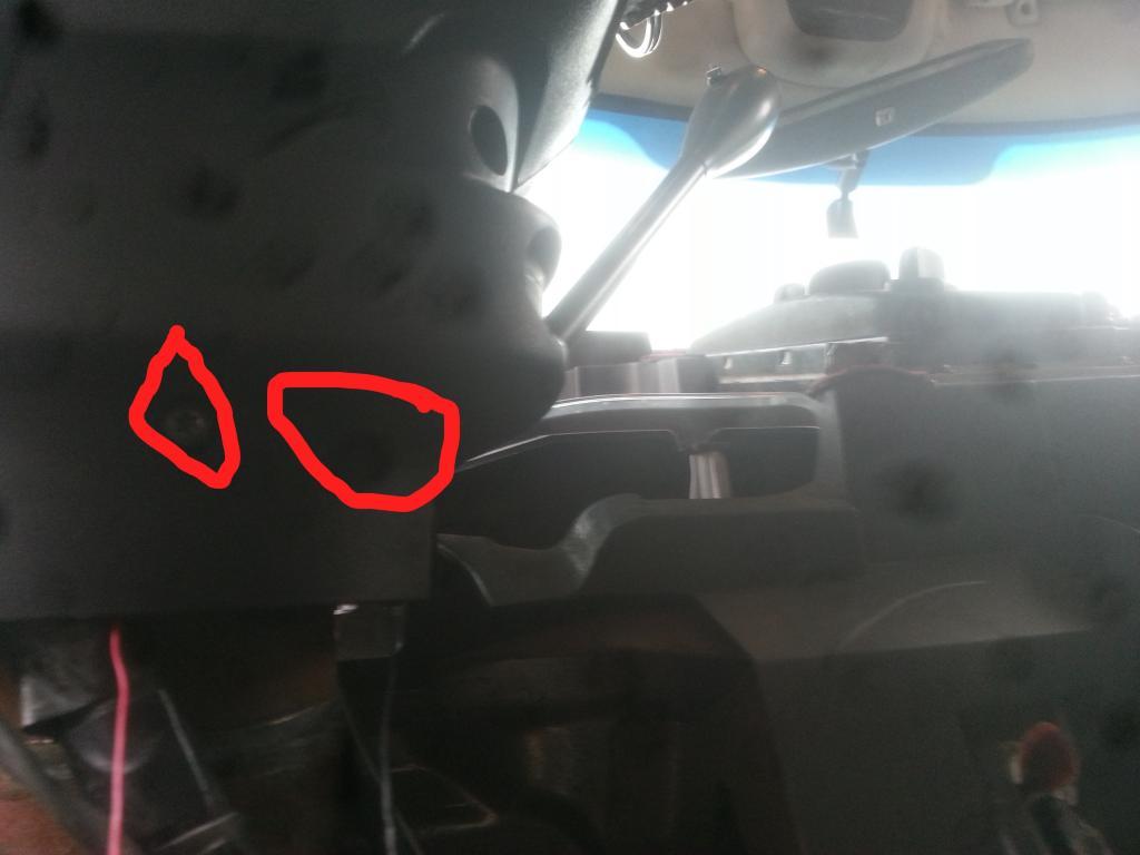
Once the bolts are removed, set them aside and carefully pry the plastic panel that covers the shift selector. The steering wheel needs to be at the lowest position so adjust it down. The plastic cover tucks under the upper steering column cover. There is an upper and a lower section held together using the above torx screws, and they also clip into each other. Pry carefully to get them to "pop" apart.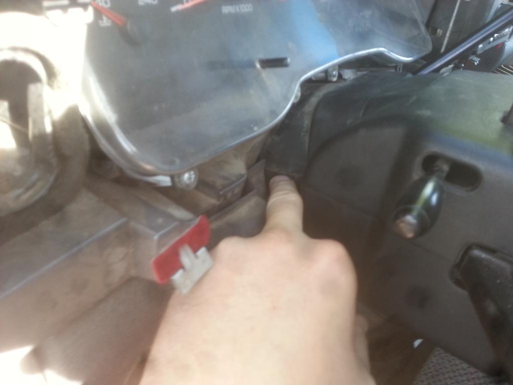
Once the upper and lower covers have been popped apart, put the lower half aside, then check to ensure your ebrake is on and the tires are chalked. After that above is you need to move the gear selector from park to 1st. this will give you enough room to pull the top cover off. It will have to be wiggled out.
Once the top cover is removed put the truck back into park.
this should expose the base of the Gear select arm. It is held in using a single pin that needs to be tapped out from the bottom using a hammer and a punch. I didn't take a picture of this for some unknown reason, but it is pretty self explanatory. The Arm will stay put with the pin removed. Carefully pull the gear selector out of the holder. it will come out with the OD wires and connector.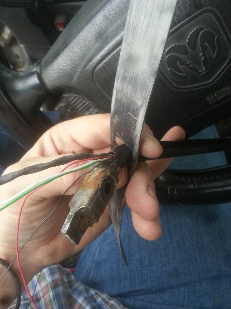
This picture shows the arm with the wires for the lockup already in it.
Notice the hole in the bottom of the arm, the OD wires go into it.
Bring the arm inside.
Next pull the OD button out. to do so pop the od button cover off using a small flat head. There is a divot where you should pry from. The cover will come off and expose the OD button. 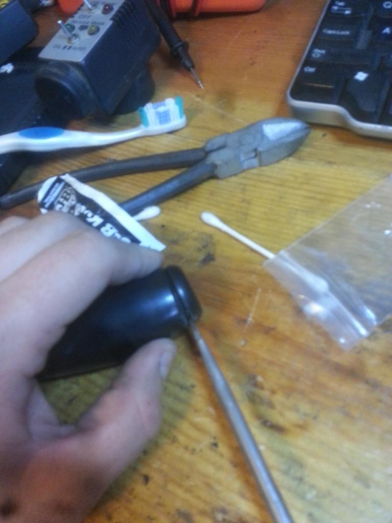
The OD button is held in via the cover so you can use a pair of pliers to pull it out.
Next is the pin holder for the OD wire connection. Use a pair of needle nose pliers to pull that out carefully.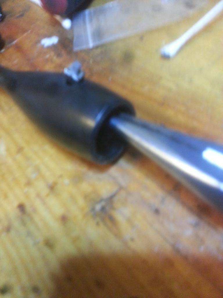
Note the position of the orientation pin. it should point up. The holder will only go in one way with the pin point towards the OD button.
Once the piece is out carefully pull the connection pins out of the black holder. 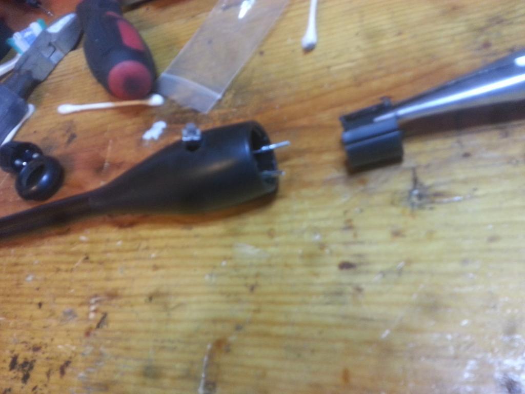
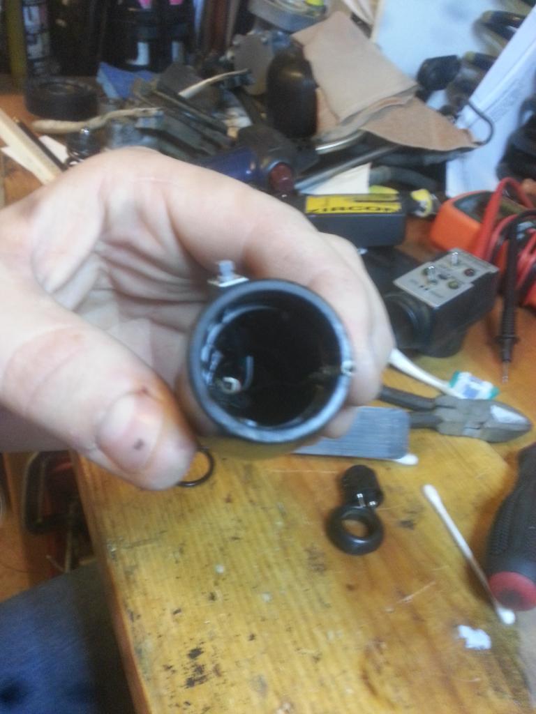
Notice the arm is hollow allowing for a switch to be installed.
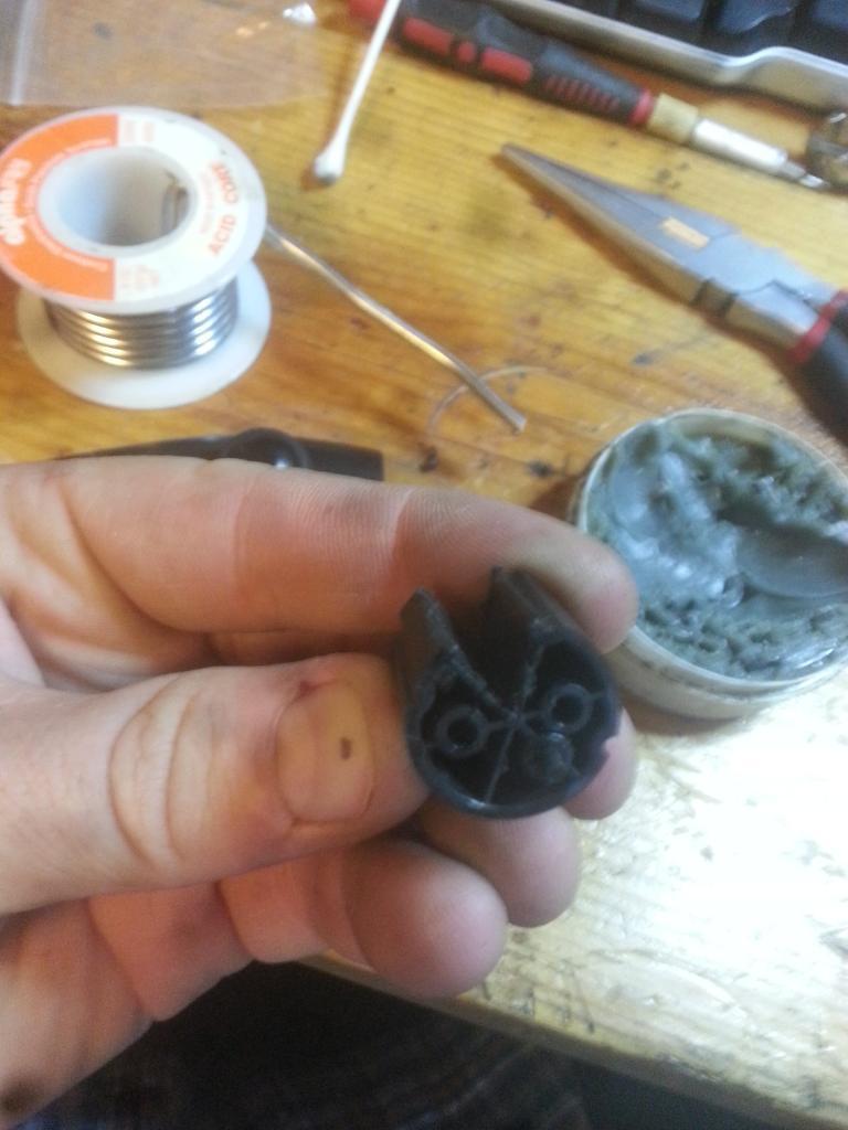
Here is a picture of the OD button holder. that I used a dremel to cut out to allow for the switch to sit in. You will have to cut this to your needs depending on the switch you go with. Ensure that you don't cut more than 1/3 of the plastic out. If you do the holder will not work. I ended up cutting out the entire area between the connector holes.
You will need 2 fairly small wires to feed through. I used wires from a older USB cable I had laying around. I was able to feed the extra wires through by pulling the OD wires completely out of the arm, then feeding my small wires through, and then re-feeding the OD wires through. The OD wires are pretty rigid so they will feed through without much issue.
Next you will need to drill a hole in the handle of the arm in the position that you like, and to the size you need to fit the switch. I used a 1/2" hole. Feed the wires through the hole you drilled and connect them to your switch in a manner that reduces the needed space behind the switch using soldier, ensure to use heat shrink wrap to keep the terminals on the button from making contact with each other.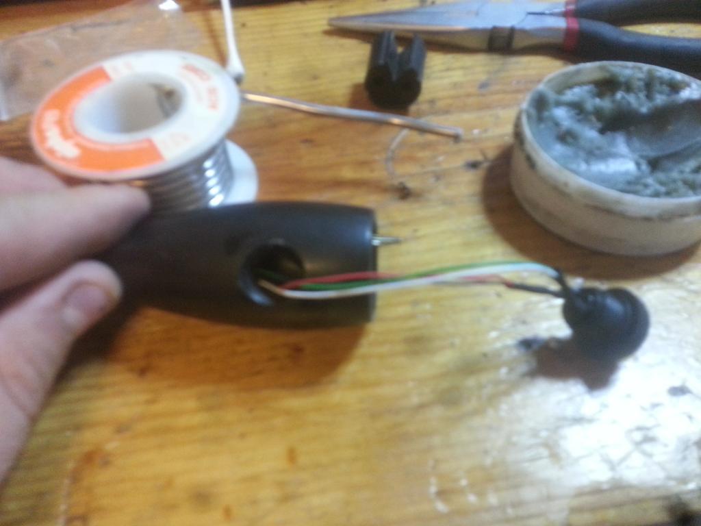
using a Multimeter with a continuity function test the Lockup wires coming out of the bottom of the arm to ensure that is is open until you press the button. Pressing the lockup button should complete the circuit.
Carefully pull your wires back through the arm to keep any spare wires from taking up space in the arm. install the button in the arm handle, and use some sort of glue, such as JB weld to hold it in place. due to spare issues, it is not easy to use a nut on the back of the switch.
Insert the OD wires into the OD button holder, doesn't matter which goes where, and reinstall the holder into the arm. Notice the area that is cut out of my holder in the image to allow space for the button. Keep in mind that the Lockup switch is simply completing a ground circuit, so if the wires touch when installed the lockup will always be triggered.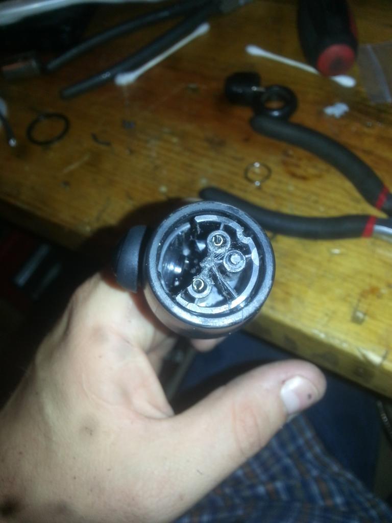
Reinstall the OD button into the end of the arm and check to issues. If all is well then reinstall the cover over the OD button.
using a Multimeter with a continuity function test the OD button to ensure that is is open until you press the button. The OD button is a Momentary switch so it should only complete the circuit when pressed and then open again once the button is released.
Take the arm back out to the truck and reinstall it. The only thing to watch out for is the shift arm is held into the holder using a pin and a spring to gate the shifter to prevent you from going from Drive to Reverse without pulling the arm backwards then up/down. You will need to use a flat head screw driver to push the spring back while installing the arm into the holder. Reinsert the pin that holds the gear selector arm. tap it flushing a hammer.
Reconnect the OD button wires under the dash.
Reinstall the cover for the gear selector base, and pop the lower and upper section back together. install the torx screws.
Remember that the cover tucks under the cover above it.
Attach one lead of the lockup switch to the wire that is run from the orange and black wire on the passenger side of the motor, Keep in mind this wire should NEVER touch a ground under the dash on it's own. Use heat shrink to protect it from accidental grounding.
Attach the other lead of the Lockup switch to a ground location under the kick panel.
Reinstall the kick panel and take her for a test drive. If you used a Momentary switch verify that lockup only happens when you are holding the button. Lockup should disengage as soon as you release the button.
-
 2
2
There are no reviews to display.