


ABS System Diagnostics / Troubleshooting
4 Wheel Anti-Lock Brake System
4 Wheel Anti-Lock Braking System Wiring Diagrams
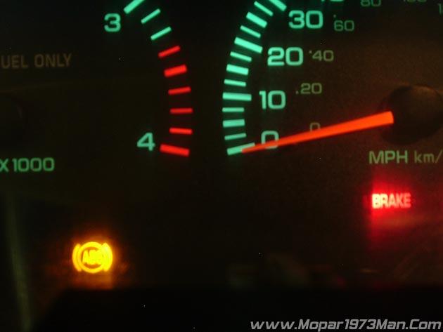
I find it's really common to hear people complain about ABS and BRAKE lights being lit. There are a few simple things you can do to diagnose your problem.
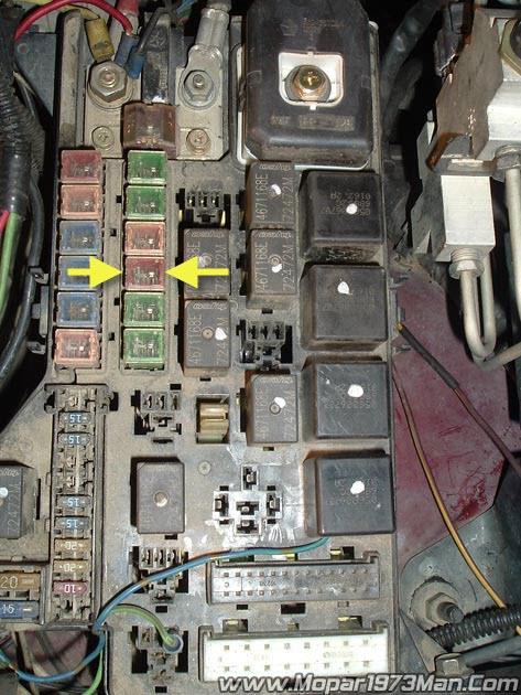
- Check your ABS fuses under the hood fuse #11 and check the #3 fuse inside the cab (driver side door jamb). Replace any that are blown.
- Step on you brake pedal and see if the tail lights light up and turn off when released. If not, repair the brake light switch.
-
Shift the transfer case into 4WD and check if the 4WD light comes on. (4WD equipped vehicles). If not repair the 4WD switch.
-
Does the speedometer work? If so, the rear speed sensor in the differential is functional.
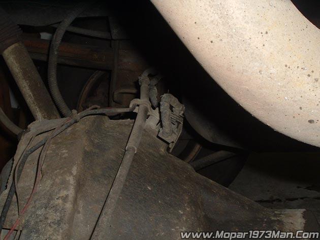
So now that you done that much that means that it one of the front speed sensors that has either become disconnected or the sensor has failed.
If the lights remain the only way I know to diagnose this correctly is at a Dodge dealer. They have the tools to hook up to the ABS computer and pull the error codes and tell you what has failed.
Once you've repaired the problem you must drive the vehicle to reset the ABS and BRAKE lights. Also, take the second and check the error codes on the ECM/PCM and reset any error codes.
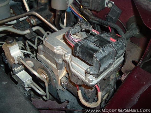
Description - CAB (Controller Antilock Brakes)
The CAB (Controller Antilock Brakes) monitors wheel speed sensor inputs continuously while the vehicle is in motion. However, the CAB (Controller Antilock Brakes) will not activate any ABS components as long as sensor inputs indicate normal braking. During normal braking, the master cylinder, power booster and wheel brake units all function as they would in a vehicle without ABS. The HCU components are not activated.
The purpose of the antilock system is to prevent wheel lockup during periods of high wheel slip. Preventing lockup helps maintain vehicle braking action and steering control. The antilock CAB (Controller Antilock Brakes) activates the system whenever sensor signals indicate periods of wheel slip. Periods of wheel slip occur when brake stops involve high pedal pressure and rate of vehicle deceleration. The antilock system prevents lockup during a wheel slip condition by modulating fluid apply pressure to the wheel brake units. Brake fluid applies pressure is modulated according to wheel speed, a degree of slip and rate of deceleration. Sensors at each front wheel convert wheel speed into electrical signals. These signals are transmitted to the CAB (Controller Antilock Brakes) for processing and determination of wheel slip and deceleration rate.
The ABS system has three fluid pressure control channels. The front brakes are controlled separately and the rear brakes in tandem. A speed sensor input signal indicating a wheel slip condition activates the CAB (Controller Antilock Brakes) antilock program. There are Two solenoid valves (Isolation and Dump valve) which are used in each antilock control channel. The valves are all located within the HCU valve body and work in pairs to either increase, hold, or decrease apply pressure as needed in the individual control channels. During an ABS stop, the ISO valve actuates, Stopping any more pressure buildup to the calipers. Then the Dump valve dumps off pressure until the wheel unlocks. This will continue until the wheels quit slipping altogether.
Operation - System Self-Test
Battery voltage is supplied to the CAB (Controller Antilock Brakes) when a speed of 15 miles per hour is reached. The CAB (Controller Antilock Brakes) performs a system initialization procedure at this point. Initialization consists of a static and dynamic self-check of system electrical components. The static and dynamic checks occur at ignition start up. During the dynamic check, the CAB (Controller Antilock Brakes) briefly cycles the pump and solenoids to verify operation. An audible noise may be heard during this self-check. This noise should be considered normal. If an ABS component exhibits a fault during initialization, the CAB (Controller Antilock Brakes) illuminates the amber warning light and registers a fault code in the microprocessor memory.
Mopar's Note: OBDII Testing / DRBIII Testing
As for testing equipment the ODBII code reader will only see P0500 error code but the DRBIII tool that Dodge dealer has been capable of seeing all speed sensors and test the ABS braking system for it faults. A lot of people ask me how much a DRBIII tool cost... They are approximate $6,000.00 for a DRBIII tool. So it might be worth a trip to the dealer and have them diagnose the system for you.
Speed Sensor Operation
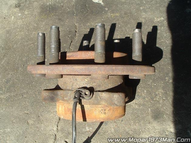
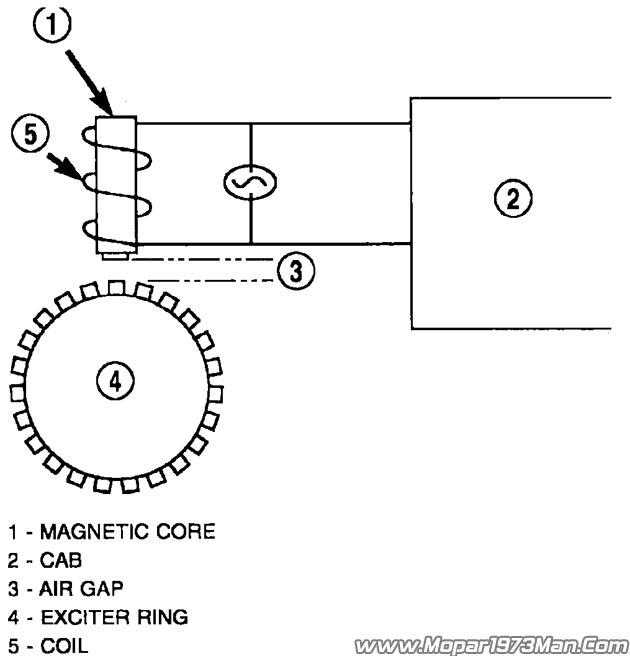
The Wheel Speed Sensor consists of a magnet surrounded by windings from a single strand of wire. The sensor sends a small AC signal to the CAB (Controller Antilock Brakes). This signal is generated by magnetic induction. The magnetic induction is created when a toothed sensor ring (exciter ring or tone wheel) passes the stationary magnetic WSS.
When the ring gear is rotated, the exciter ring passes the tip of the WSS. As the exciter ring tooth approaches the tip of the WSS, the magnetic lines of force expand, causing the magnetic field to cut across the sensor's windings. This, in turn, causes current to flow through the WSS circuit in one direction.
When the exciter ring tooth moves away from the sensor tip, the magnetic lines of force collapse cutting the winding in the opposite direction. This causes the current to flow in the opposite direction. Every time a tooth of the exciter ring passes the tip of the WSS, an AC signal is generated. Each AC signal (positive to negative signal or sine wave) is interpreted by the CAB (Controller Antilock Brakes). It then compares the frequency of the sinewave to a time value to calculate vehicle speed. The CAB (Controller Antilock Brakes) continues to monitor the frequency to determine a deceleration rate that would indicate a possible wheel-locking tendency.
The signal strength of any magnetic induction sensor is directly affected by:
- Magnetic field strength; the stronger the magnetic field, the stronger the signal
- Number of windings in the sensor; more windings provide a stronger signal
- Exciter ring speed; the faster the exciter ring/tone wheel rotates, the stronger the signal will be
- Distance between the exciter ring teeth and WSS; the closer the WSS is to the exciter ring/tone wheel, the stronger the signal will be
The rear WSS is not adjustable. A clearance specification has been established for manufacturing tolerances. If the clearance is not within these specifications, then either the WSS or other components may be damaged. The clearance between the WSS and the exciter ring is 0.005 - 0.050 in.
Resetting the ABS / BRAKE light
You must repair/replace the damaged sensor/unit of the ABS braking system then drive the vehicle a short distance at road speeds before the lights will go off. The ABS module does an on the fly diagnostic of all the system and if all sensor is reporting properly the system will automatically reset at a speed of 15 MPH.
CAB (Controller Antilock Brakes) Inputs
The CAB (Controller Antilock Brakes) continuously monitors the speed of the differential ring gear by monitoring signals generated by the rear wheel speed sensor. The CAB determines a wheel locking tendency when it recognizes the ring gear is decelerating too rapidly. The CAB (Controller Antilock Brakes) monitors the following inputs to determine when a wheel locking tendency may exist:
- Rear Wheel Speed Sensor
- Brake Lamp Switch
- Brake Warning Lamp Switch
- Reset Switch
- 4WD Switch (If equipped)
CAB (Controller Antilock Brakes) Outputs
The CAB (Controller Antilock Brakes) controls the following outputs for anti-lock braking and brake warning information:
- RWAL Valve
- ABS Warning Lamp
- Brake Warning Lamp
Mopar's Notes: P0500 Error Code - Explained
Since 4 wheel anti-lock brakes rely on 2 front axle sensors and 1 rear wheel sensor. The CAB (Controller Antilock Brakes) is watching the speed output from all 3 sensors at one time. So when on a slick surface like ice, gravel, wet pavement, etc. when you accelerate rapidly and cause the rear tires to spin the rear speed sensor jumps up in speed rapidly and the front 2 sensors could be at zero speed yet. So the CAB (Controller Antilock Brakes) can't understand how the rear half of the truck is doing say 35 MPH and the front half is doing 0 MPH. POOF! P0500 code is thrown.

-
 1
1