
I took some pics as I did mine last week, and thought I'd try making a write up on it.
Basic tools etc. you'll need are , approx. 8qts. of ATF+4/filter,Governor press. solenoid and transducer,1/4' drive torque wrench, 1/4" & 3/8" socket sets, basic metric wrench set, a pick or small screwdriver, a drill with a 1/2" bit for the drain plug kit, big catch pan:thumbup2:, and a paint pen or sharpie,plus whatever I forgot:ashamed:
1) Drop pan to drain the fluid, the easiest way is to go around and loosen them all just a turn, then work from one side loosen the bolts in steps. The idea is to get the pan to drop on only one side to minimize spilling and dump the fluid off a corner- easier said than done. I'd recommend putting a drain plug in the pan while it's off ,to make draining the fluid easier.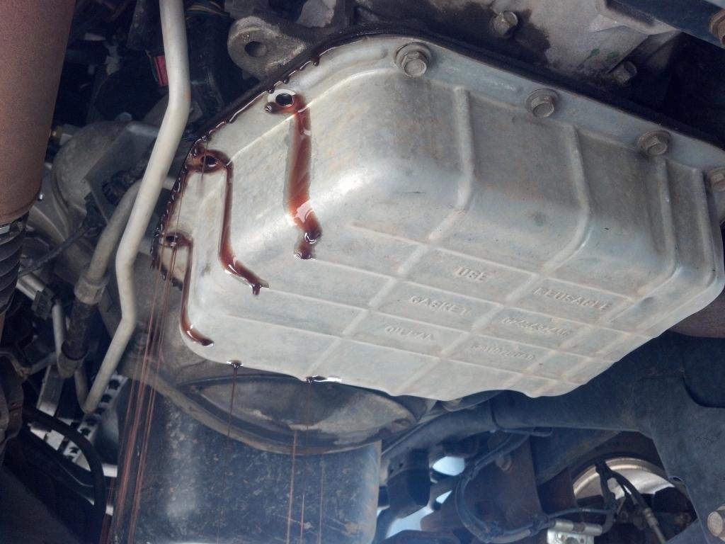
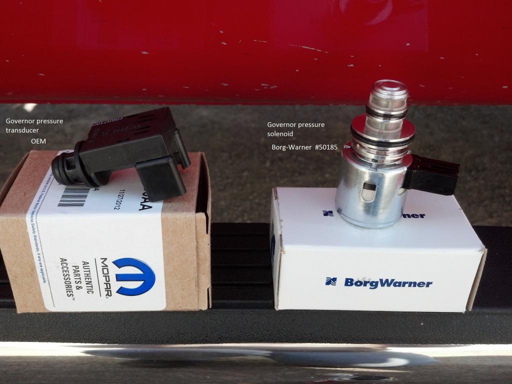
2)Pic of the Solenoid and transducer, I used the Borg-Warner 50185 Solenoid upgrade instead of the OEM , recommended because of it's larger magnet, and the difference in my shifts is amazing..
3)Remove the filter and there they are, your going to need a torx bit-T40 I believe and socket to drop it out, but first you'll need unplug the the electrical connectors to the solenoid and transducer, go easy with them ,the hot cold cycles tend to make them brittle.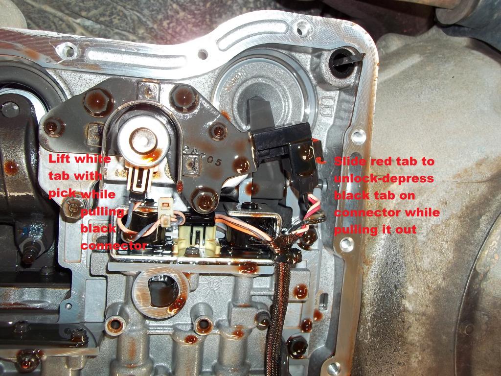
4)I removed the two torx screws and bolts, leaving the bolt closest to the rear band adjuster in, this will hold the base on the valve body,no risk of gasket damage doing it this way.At this point you can pull gently on the stamped retainer and the governor solenoid will pop out of the base,since its held in a slot in the retainer. The transducer will remain , just make a note of it's orientation and then pull it out as well. If you notice, there is a slot in the retainer that indexes to a groove in the transducer also, thats to hold it in after reassembly 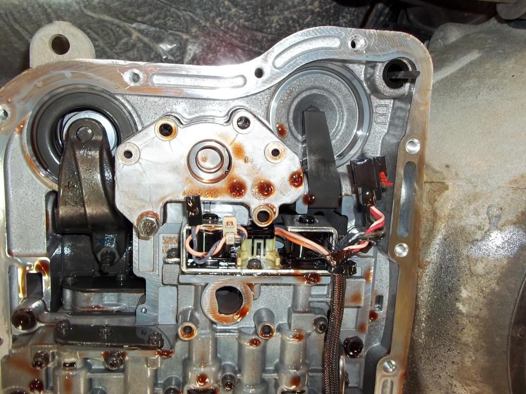
Comparison pic old vs. new.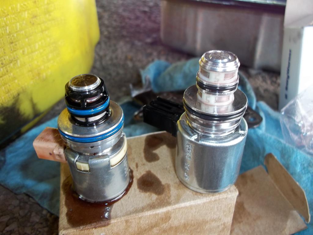
5) Slide the transducer into the spacer after coating the o-rings with some ATF, make sure that it's turned so that the slot will line up properly with the retainer ,oil the o-rings on the solenoid and slide it into the slot in the retainer.Hold it in the bracket ,and reinstall the opposite of how you removed it,just make sure the retainer is lining up with the slot in the transducer as you guide it in. It should go in easily, if you have to force it stop and verify everything's all lined up, before you go primal on it  torque all the fasteners, hook up the connectors and your done! Eezy peezy..
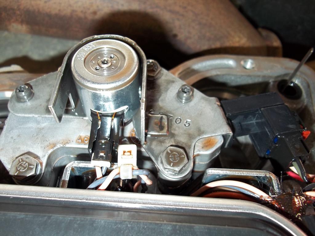
6) Now's the time to adjust the rear band, it's a easy job but it has to be done right,if you don't do it properly, bad (expensive) things are probably coming your way. That being said, crack loose the lock nut, and back it off 4-5 turns so it doesn't bottom out as you tighten the band. Get yourself a 1/4" torque wrench and 5.5mm socket.Tighten the band to 72 INCH lbs then back off 3 full turns ,hold the adjuster (very important) so it doesn't turn as you tighten the locknut-25ft lbs. Here's a couple of tips, use the paint marker on the adjuster to make a reference mark, AFTER you've reached your final torque.Then carefully take note of it's location and back it off the 3 turns. Then after you tighten the locknut, this mark also gives you a positive verification that it hasn't turned, as you tightened it. It's much better to err on the loose side band adjustments, too tight is probably gonna break some parts. I personally like using a beam type wrench so that I can see it coming up on it's final torque, and I also back off the torque values by 10% since it's a worn in band- right or wrong that's my opinion only. 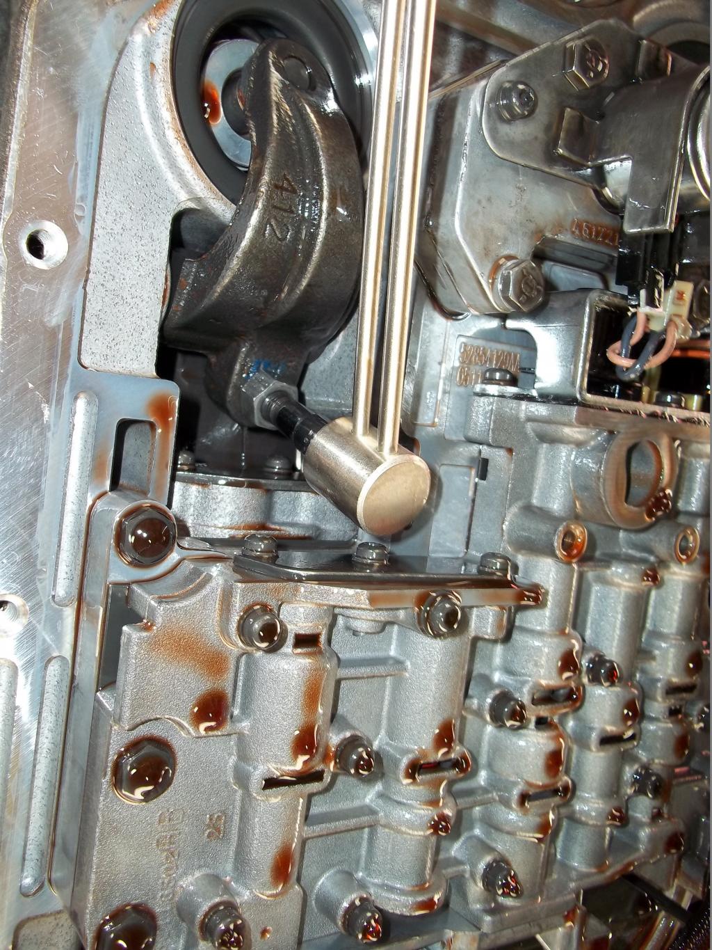
I don't have any pics but,the front band is essentially the same procedure. Its a little difficult to get to and if you have one, a crow foot wrench will come in handy! Back off the lock nut a few turns ,use a torx bit to tighten the adjuster to 72 INCH lbs. then mark it and back it off 1 3/4 turns ( I went 2 turns because of my err a bit on the looser side opinion) then hold firmly as you tighten the lock nut- if you can torque it great! your a better man than I,there's just not enough room in there for my pudgy hands :shrug:a wrench and a torque wrench, just wing it ,it will be fine..
7) Install the filter
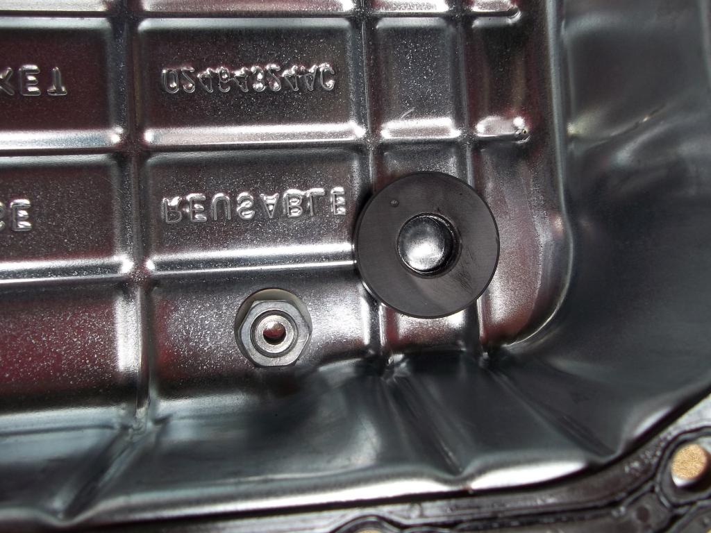
8) Pick a spot on the pan where your sure the drain plug wont interfere with anything, drill a 1/2" hole ( at least in my kit) and install per instructions.This kit had a o-ring for the plug seal, only no groove to retain the o-ring when you tightened it, so I replaced it with a fiber washer.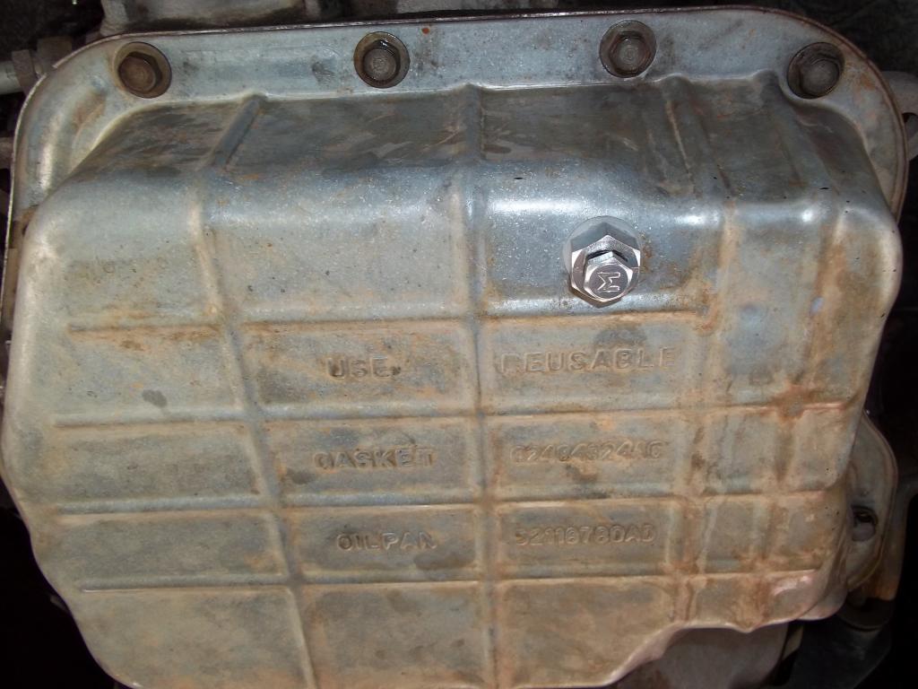 Install the pan, tighten the fasteners in a criss -cross pattern and fill with fluid.
9) I started with 5qts. of fluid ,fired her up and let it idle in neutral , and then added more fluid, while checking for leaks, as needed to bring the level up to full.
Your done! Take her for a drive and recheck for leaks , and fluid level..
-