


article will show you how to calibrate a HE300VE turbo using a cheap arduino board and a Canbus shield.
PLEASE NOTE**** This is not a magic pill for fixing issues with the turbo actuator. If the actuator is bad then it will still need to be replaced. We get a lof of questions similar to "hey I ran this and the turbo still doesn't work" This will not fix an actuator, only calibrate a good actuator to the physical limits of the turbo vanes.
Parts
arduino uno $15-$30
Arduino Uno Canbus Shield $25
Plugs ~$5
Wires ~ $5
Code
Canbus Library
This code will simple send the calibrate command to the turbo after 5 seconds of having power applied to the unit.
#include <SPI.h>
#include <can.h>
#include <Wire.h>

#define mode NORMAL // define CAN mode
#define bitrate 250 // define CAN speed (bitrate)
MCP CAN1 (10);  //****This might be any pin 9 / 10 / 11  depending on the cnabus shield.  Adjust to fit your needs


unsigned int final_vane_position;
void setup() {
  // put your setup code here, to run once:
 // Initialize Serial communications with computer to use serial monitor
  Serial.begin(115200);
  // Set CAN mode and speed
  CAN1.begin(NORMAL, bitrate);
  delay(5000);  //wait for 5 seconds

}

void loop() {
  // put your main code here, to run repeatedly:
  final_vane_position = 500;
  byte lo_byte = lowByte(final_vane_position);
  byte hi_byte = highByte(final_vane_position);
  byte data[] = { lo_byte, hi_byte, 0x02, 0xFF, 0xFF, 0xFF, 0xFF, 0xFF }; // data message with an added counter
  // data[2] = 0x02 for recalibrating gearbox
  // Load message and send
  CAN1.send(0x0CFFC600, extID, 8, data);

}
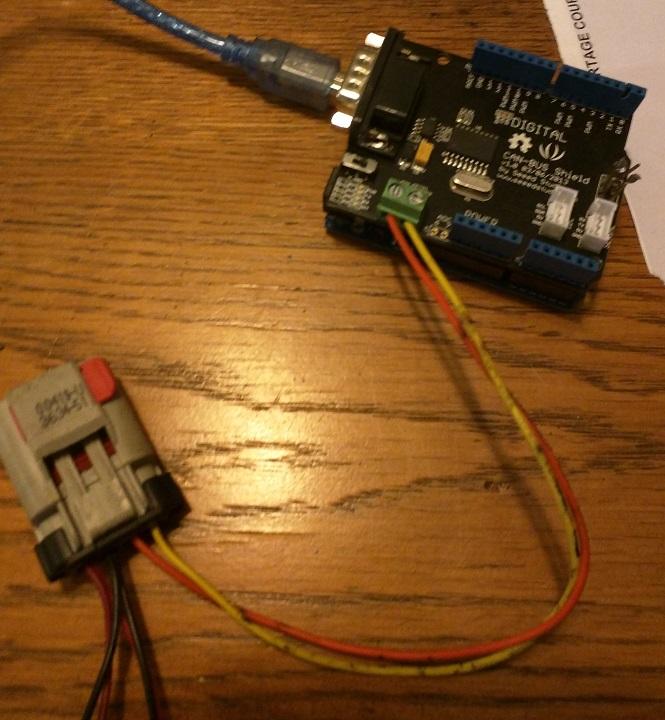
How to Connect everything
I will go into some detail here.
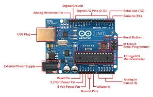
First basics of the arduino uno and cabus_ shield.
Arduino boards allow you to "stack" shields onto it via the pins on the outside edge of the board. Each Pin on the arduino and shield correlate to the Pins the code below. You can think of the Arduino as a Small computer and the Shield as a device to perform another specific task, like WIFI or Audio or in this Case Communicate on a Canbus Network. Stacking the shield onto the Arduino allows the arduino to talk in Canbus.
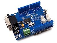
First is the Arduino Uno Next is the Can bus Shield that you stack on top
Together they should look like this. notice how they are connected, stacked on top of each other with the pins from the shield extending into the Arduino board.
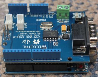
Each Shield will use some pins so your code must take that into consideration. Just as an example the can bus shield might use pin 10 and 11 ( I dont remember off the top of my head) so in your code you can't address those pins outside of the canbus shield use.
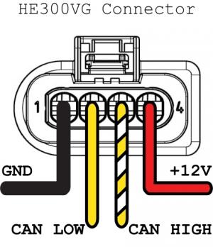
Wire up the turbo
Early Holset HE351ve's have a different wiring than late Holset HE351ve turbos
Easy way to tell the difference is to look at the actuator, if it has a wiring pigtail coming out of it it is a early 351ve if the connector is built into the actuator it is a late he351 or a he300 ve, which is the same size as the he351ve.
Early Holset He351ve Wiring
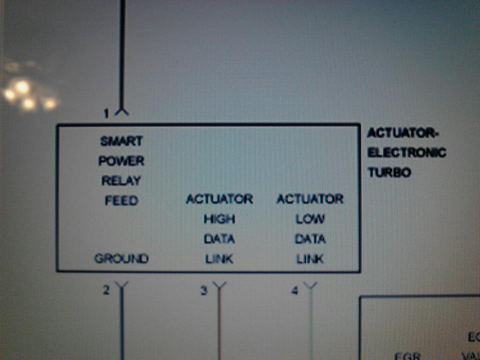
Late He351Ve / He300ve Wiring
Connectors PN's can be found over at Lilbb.com
http://wiki.lilbb.com/holset_vgt#connectors
He is a guru in terms of the turbo and has a GREAT off the shelf type of controller.
You want to wire the Power / ground to a fused line to the battery, Don't try to power though the arduino as the turbo can pull north of 15 amps.
Wire your CanHigh / Low to the Arduino shields high / low screw terminals.
Upload You The Code
Url's are provided in Text to step you through the process.
1. Download the Arduino program
2. Plug in your Arduino to the computer, select the right settings for the uno
3. Double click the turboreset.ino project, which will open the arduino IDE.
4. Install the canbus library. CANLibrarymaster.zip
5. Upload to the board from the Arduino program
Operating The Calibrate Tool
Line up the actuator arm on the turbo if the actuator was removed.
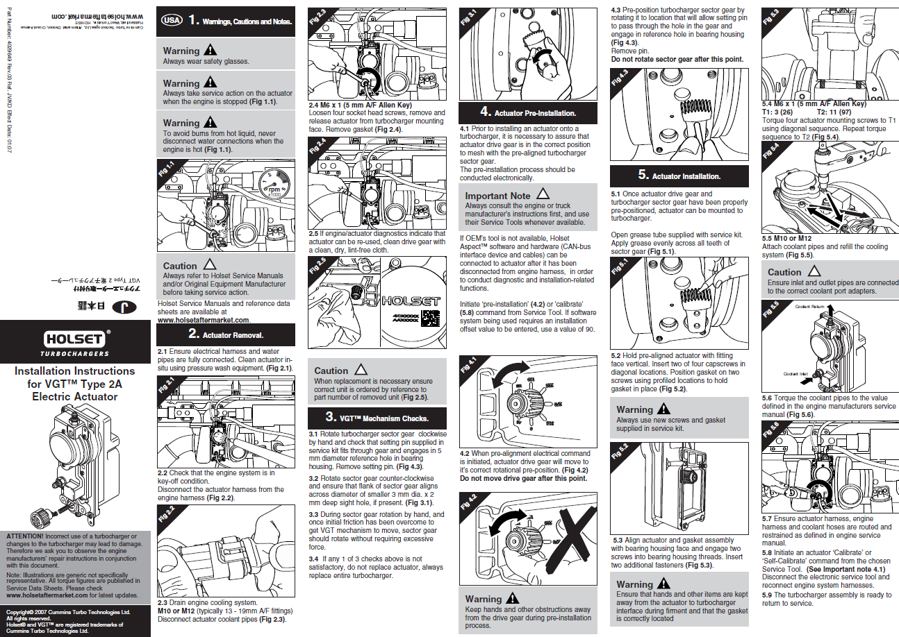
Disconnect the Turbo wiring from the truck, this will set a code it's ok. Plug in your reset tool to the turbo, then connect power to the arduino board. After 5-10 seconds you should head the turbo cylce the vane position slowly. Once The turbo comes to rest it is done. Disconnect the arduino and plug the truck back into the turbo .
If you continue to have issues with the turbo it is very likely that your actuator is no longer working as designed.
If you found this helpful please shoot a donation my way. Everything I do is to help support the community.
Thanks
-Me78569
![]()
-
 1
1
There are no reviews to display.