


HE351ve Holset VGT Controller
This article is for the standalone controller / tuner needed to control a Holset HE351 ve He351 VGT turbo from a 6.7 Cummins. This controller will help you tune the holset he351ve vgt turbo for your truck. It is is %100 open source you can tune the turbo in any manner you like. It will take some trial and error to tune the holet he351vgt, but the pay off is worth it. The he351ve really shines when it comes to low end power and having a flat torque curve.
He351ve Airflow Specs
The reason for wanting this turbo comparted to another aftermarket turbo are, Increased flow over a hx35 turbo ( 60lb/min to 69 lb/min) built in Exhaust Brake functions, Cheap turbo cost, fast spooling, and good mpg's if you have it tuned right. For a 5.9 Cummins the he351ve makes a great towing turbo for hp levels up to 500. It will be hot at 500hp but it is possible, not recommended, but possible.
This should also work for He451 ve vgt or other Holset variable Geometery turbos. 551 431 turbos
There is a certain amount of DIY needed to get this setup on your truck. You will need to learn the arduino system, how to wire it, power it, etc etc etc.
Basic Video
Here is a Video of the basic code and how it works with the VGT turbo
If you read through this and have ANY questions, feel free to Post to the Ongoing thread covering the progress on this project You can Find the Forum Link HERE
Parts:
Here are the list of parts that are used. you can void the code to use one or all of the sensors, but this list is for everything.
Arduino uno: http://www.amazon.com/Arduino-Board-Module-With-ATmega328P/dp/B008GRTSV6 $25
Canbus Shield: http://www.amazon.com/CAN-BUS-Shield-Compatible-Arduino-Seeeduino/dp/B00NQVH666 $40
Exhaust/boost sensor 0-100 psi: http://www.auberins....products_id=271x2 if you want to control the turbo on both exhaust and boost. $56 a piece and they come with 3 wire pigtails.
Potentiometer push pull 10k linear: Mouser Link $15
Momentary on button switch: havent picked one up yet that I like. Currently using a computer button.
Wire: 16 gauge should be fine 100' should be enough, ensure to get good quality wire
Connectors: I used 2x DT06-12SA and 2 x DT06-12PA along with all hardware, ebay link
LCD Screen: I used a 4x20 screen with a I2C adapter. Searching EBAY should find you one. Click link to see search.
Turbo Connector 4 pin: Mouser Connector Link 54200410-B Pins 10762770
Turbo RPM Connector: Mouser Connector Link PN: 282087-1
Software:
You will need to download the Arduino program: Arduino - Software
You will need the libraries that I use. You can Download them all from My Google Drive
Download the Canbus library: Dropbox - CANLibrarymaster.zip (thanks to Farm828)
download the LCD Library: Dropbox - LiquidCrystal.zip
Download the Freqmeasure library https://www.dropbox.com/s/yv98sgdllckc9z4/FreqMeasure.zip?dl=0
Download the Timer library https://www.dropbox.com/s/xa0lxny0pftdi6h/Timer-master.zip?dl=0
Basic starter Code downloaded here: Dropbox - HE351VE_Control.ino (thanks to Farm828) This is the code from CF without my changes
You can edit the code by voiding the sensors "//" you are using in the right section, defined.
My code has changed significantly from the above.
How to Connect everything
I will go into some detail here.
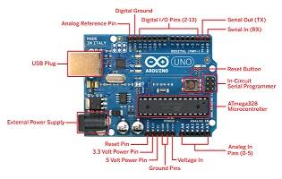
First basics of the arduino uno and cabus_ shield.
Arduino boards allow you to "stack" shields onto it via the pins on the outside edge of the board. Each Pin on the arduino and shield correlate to the Pins the code below. You can think of the Arduino as a Small computer and the Shield as a device to perform another specific task, like WIFI or Audio or in this Case Communicate on a Canbus Network. Stacking the shield onto the Arduino allows the arduino to talk in Canbus.
First is the Arduino Uno Next is the Can bus Shield that you stack on top
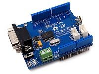
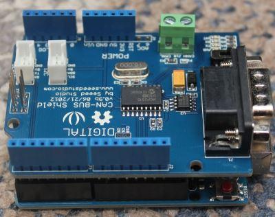
Together they should look like this. notice how they are connected, stacked on top of each other with the pins from the shield extending into the Arduino board.
Each Shield will use some pins so your code must take that into consideration. Just as an example the can bus shield might use pin 10 and 11 ( I dont remember off the top of my head) so in your code you can't address those pins outside of the canbus shield use.
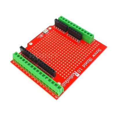
Next you will need to connect all the wires to the sensors. I used some weather proof plugs to make my arduino detachable from the rest of the wiring harness. You will need to figure out a way to connect your harness to the arduino. I used a shield to do this like this.
Now for actually connecting the wires from the sensor to the board you will need
3 wires for boost
-5v
-Sensor return ( pin A0)
-Ground
3 wires for Drive
-5v
-Sensor return ( pinA1)
-Ground
3 wires for Pot
-5v
-Sensor return ( pin A2)
-Ground
1 wire for TPS
-Sensor return ( pin A3)
2 wires for PotSwitch
-Ground return ( pin D2)
-Ground
2 wires for EBSwitch
-Ground return ( pin D9)
-Ground
4 wires for LCD screen
-5v
-Ground
-SCL ( Pin A5)
-SDA ( Pin A4)
2 wires for The turbo Shaft speed input
-positive signal ( goes to the 9924 chip)
-Neg signal ( goes to the 9924 Chip)
-Output from pin 7 of 9924 chip to pin 8 of the arduino.
Here is an example from www.Arduino.cc of how to wire a simple pot/sensor. you can see 5v. ground, and the sense return going to pin 2
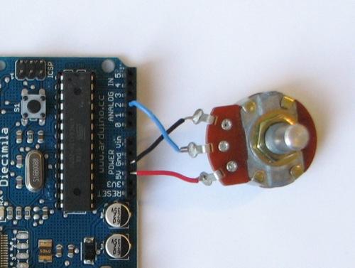
Keep in mind some shields provide more 5v outputs and grounds than others. You can splice the grounds together and run them into one or a couple grounds on the arduino.
The Code
He351ve Boost/Drive Controlled
My basic code is as follows for controlling the he351ve using boost and drive.. You can change it / use it / do whatever you like.
You can download the tab'd version of the boost controlled code HERE Keep in mind that it is VERY easy to overspeed the he351ve turbo. Holset rates the turbo to 130,000 rpm. Using the code below I was seeing speeds of up to 160,000 rpm. ENSURE you tune the turbo for your fueling. I found that it is nearly impossible to manage the turbo efficently without using shaft speed so I do not recommend driving the turbo on this code. You will run into egt issues, you will run into shaft speed issues.
the boost map code is no longer updated so the version that is hosted is what you get.
I have noted in the code as much as I could,.
The basic run down for what this code allows is.
- During normal driving it will allow you to choose from 3 different boost maps, performance, daily, and Economy by using the pot, with the switch off, to have low/mid/high input from the pot. Vein position is managed by the boostmap until 30 psi is hit. after 30 psi boost the program will switch over to DPmanage and it will attempt to keep drive pressure at 50psi ( defined by code "maxexhaustpressure") which keeps drive to boost ratio within check, 40psi boost theory max 50 theory max drive 40psi/50psi gives a ratio 1.25:1. the HE351 turbo seems to like a high ratio on the lower end. I see ratio of 2:1 all the time until boost is above 20psi, then it starts to level off and come down closer to 1:1.
- Turning the pot switch on allows you to manually set the vein position as long as throttle input is below %25. If you turn the pot all the way to 1000 value ( turbo is limited to positions 40-970) it will lock the turbo %100 open regardless of throttle input. You can use the pot to set the turbo position to small and allow for fast warmup.
- Exhaust brake will work provided pot switch is off and throttle input is below %5 it will try and keep EB pressure at 45psi per the code. If pressure increases to above 45 psi it will slowly open the veins.
He351ve TURBO RPM based Controller Code
Thanks to hakcenter at lilbb.com I have edited my code to include his turbo shaft speed controller for the turbo. It is smoother and more refined than using the boost/drive to control the vanes. You will not run into EGT issues or shaft speed issues using this code. You can download the code in the attached zip ** versions after 1.11 are for the arduino mega so if you are using an arduino uno ensure you use version 1.11
This requries you add a 9924 chip to your controller to count rpms. I highly suggest you visit www.lilbb.com and look at his controller shield for the arduino if you want a more out of the box controller.
Additional Parts
Umax 9924 Chip: Mouser link
Pullup Resistors 10k: SparkFun Link
You can find the documentation for the 9924 HERE, Click "Data Sheet"
Chip:
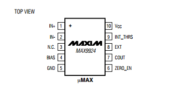
Pins:
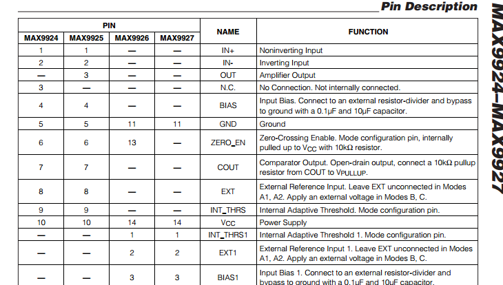
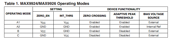
Basics on wiring for A2 Mode:
1 vr+ ( turbo +)
2 vr- ( turbo -)
3 NC ( not connected)
4 GND
5 GND
10 +5v
9 GND
8 NC
7 IO8 + 10k + 5v pullup
6 GND
Top left is 1, Top right is 10
Bottom left is 5, Bottom right is 6
He351ve Shaft speed Controller with ODB interface
In my quest for a better controlled turbo I have decided to interface with a pretty cool OBDII interface. It is $39.99 shipped and should plug and play into your arduino. It converts the Canbus info into serial signal that can be read by the arduino via the library that was created for the device. You can find it Arduino OBD2 reader
You will plug this into your vcc, gnd, tx, and rx pins of the arduino. Due to the age of the cummins there is a limited amount of info that can be used, but it does read RPM, TPS, Coolant, and IAT ( I think) maybe some other stuff, but I am not sure.
The biggest perk to this is you can now use Engine RPM in your code to increase the vane size at higher RPMS while keeping the turbo responsive down low.
You can download the code in the attached zip
This code is still Beta so use at your own risk.
Spool speed with the He351vgt.
I went to about %35 throttle at about 8-9 seconds into the video.
If you found this helpful please shoot a donation my way. Everything I do is to help support the community.
Thanks
-Me78569
![]()
-
 6
6


There are no reviews to display.