


Fuel/Air separation system
By: Sam Martin - AKA: SamIAm @ CumminsForum.Com
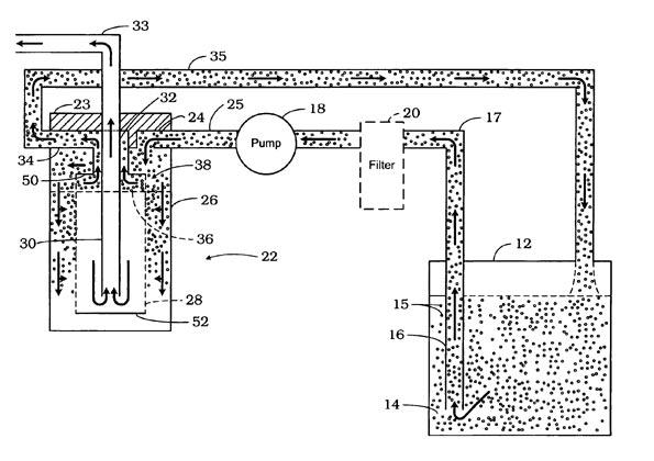
The principle of fuel/air separation used by Fass and AirDog uses a fuel soaked filter media to provide a barrier through which fuel flows easier than air. The design provides a path of least resistance on the inlet side of the filter for the air to follow. This is accomplished by porting the top of the filter housing on the inlet side of the filter. This is what FASS and AirDog have done with their systems. I believe AirDog has gone a step further by providing an additional port (small) on the filtered side in the event that some air would get through the filter. A basic drawing/illustration of their systems can be seen at
http://www.freepatentsonline.com/6892710.html
And looks like this
The benefits seen from providing your engine with vapor free fuel typically include 1) increased fuel economy. 2) Decreased emissions 3) increased horsepower and torque.
Check out pureflowtechnologies.com for a good write up on the effects of air in diesel fuel.
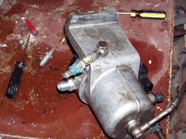
I built a test model from a standard fuel filter housing bought at the farm store. The inlet and outlet are both 1” reduced to 3/8” hose barb. I put a ¼” NPT port in the top of filter housing on the inlet side. In the picture below you can see a port in the side of the inlet. That port was not tested for effectiveness in removing vapor. Although I think it would work. I drilled & tapped another port through the top of the flange to use as a return line.
I then installed a 3/8” pipe nipple about 3” long in the outlet to use as a down tube in the center of the filter canister.
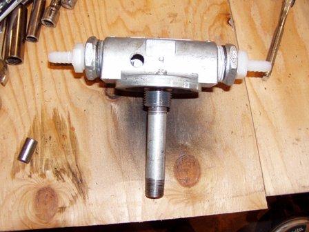
The filter housing with an extra port drilled and tapped in the inlet and 3/8 pipe nipple threaded into the outlet as a down tube. The port I tested for the return line is actually drilled vertically through the flange on the filter housing and is not visible in this photo.
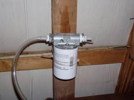
This is the bench model less a few (borrowed) parts.
To develop a system like this one needs to know a few things about the fuel demands of the particular vehicle you are putting it in. (thanks to some help from Michael Nelson) I have a 2000 Dodge 2500 24v CTD with peak demand being about 28-32 GPH (gallons per hour) of fuel and I wanted no less than 12 PSI @ WOT (wide open throttle). My truck is not too far from stock L ….yet J
I found from bench testing (backwoods as it may be) there needs to be as much fuel as used at full demand (WOT) also flowing back to the tank to carry the air/vapor with it.
So I needed a total 64 GPH @ 12 PSI. It is important to measure peak fuel flow needed at the pressure the system will see @ peak demand (12 PSI) in my case. If you set up the metered return flowing 32 GPH at a higher pressure, the fuel pressure will drop at full demand and the return volume will decrease rendering your system less than optimal if not completely ineffective.
I used a Raptor 150 GPH pump for my setup and installed it according to instructions. It comes with a ½” line kit to go from the tank to the pump, then from the pump to the filter housing.
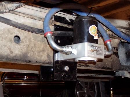
For the return line I drilled and tapped the back of the stock filter housing to accept a banjo bolt connection, using the connection that was originally on the suction side of the stock lift pump. I removed the fuel heater and drilled through the housing as near to the top as I dared. The only thing I don’t like about this design is that I haven’t figured out how to put a down tube in this apparatus since it is built from a water separator housing equipped with an up tube. It still works although I’m still considering options for improving the design. After drilling and tapping the hole I cleaned the filings out of the housing and re-installed the heating element.
I then used the original supply line with the quick connect (Dorman fitting) for the return line. I had to move the line forward a bit to reach the filter housing.
The next step was to tie the return line into the tank. I had cut the steel line in front of the tank for experimenting so I ran a 3/8 fuel line from there. The best is to tie into the filler tube or the auxiliary connection on the tank module. The systems you can buy are set up to tie into the filler tube but only because the auxiliary ports vary in design and/or placement on any given model year and would make it harder to provide a kit to match the vehicle.
For metering the return fuel flow I put a valve near the end of the return line. It would also work to put one on the filter housing instead of in the line. I adjusted the pressure on the pump as well as adjusting the valve until I got about 40 GPH @ 12 PSI. The return flow should be calculated to your fuel demand and desired pressure if you want optimal performance without taxing the pump any more than necessary. I wanted to go a little over 32 GPH just to be on the safe side.
After hooking everything up, I adjusted the pump to 16-17 PSI with the truck idling so at peak demand I see about 12 PSI. The pump still has a lot of adjustment left if I wanted to turn it up for a greater fuel demand... Soon
There are no reviews to display.