Jeeper Jimmy
Unpaid Member
-
Joined
-
Last visited
Everything posted by Jeeper Jimmy
-
Mike, That looks like somebody got mad at it and took a bite out of it. If that round,black thingy were whole I would say it is a diaphragm. (as illustrated on Jasper's web site but not found in your breakdown). That's a very strange combination of parts; looks like the hub of a vane pump, a beat up timing piston and a ruptured (or cut) diaphragm? (Probably not ruptured, because it's too clean a cut) I think this is part of somebody's training aid, and maybe that the chunk has been deliberately cut out to show what it is made out for whatever reason I can't imagine. Back to the piece you found: How are the plastic and metal parts tied together? Are they bonded or independent? Is there anyway for pressure to get to the 'plastic' part? Is the plastic part on the bowl side or the feed pump pressure side? Also, is that snap ring the only thing that holds that piece you've got into the body? The reason I ask is I've always been under the impression that low feed pressure can damage a diaphragm but high feed pressure cannot because the diaphragm had a strongback between it and the vane pump pressure to prevent high feed pump pressure from flexing the diaphragm in that direction (probably more folklore?). The mystery continues.
-
Since nobody yelled at me very loud, I'll put my foot in my mouth one more time. In the interest of keeping his thread alive, I did some calculations. I won't bore you with these calculations, but if anybody really cares, I can post them. First off~~we are not talking big numbers here; we're talking fractions of millimeters and cubic millimeters. By my calculations, the diaphragm only has to flex (or move) about 0.12 millimeters (mm) (about the thickness of a piece of 20 weight copy paper) to absorb the high-pressure spill coming back into the feed bowl. And that is assuming full volume of the injection pump pistons is spilled back to the fuel bowl. Any amount (about 50 cubic mm at max engine load or 4.5 cubic mm at idle) of fuel being injected into the engine will make this number smaller. Again, this is a very small amount of fuel, but it's coming back at a bone-jarring pressure and the fuel bowl has to recover in a matter of milliseconds to get ready for the next operation. I used Mike's pictures to give me a best guess at dimensions for the feed bowl. I used 3 inches for the diaphragm with 1.5 inch hole taken away. I used one inch for the bowl depth. I took the plunger dimensions from the VP44 Service Manual. I used 7.4 mm for the plunger diameters (there are three). I used 3.5 mm for the plunger stroke. I whole-heartily agree that it would be probably impossible to rupture a piece of one-tenth inch hardened steel. I don't see that could possible happen. I also think I agree that you're not going to flex that piece of steel much. The point I'm trying to make, I guess, is that when you put a high pressure spike of fuel back into closed system, something has to give. And there isn't much time (may 100 milliseconds to fix it.) I guess that's enough~~ Back under the desk humbly, jimmy
-
I apologize, Michael; this is going to look like another book, but~~~ First off: I don't believe that I have read from any credible source that high feed pressure could rupture the diaphragm--just low feed pressure. I think it's pretty well established that high feed pressure can cause hard starting of a warm engine. I think this is caused by abnormal operation of the timing circuit causing it to not be in its retarded position during startup. I guess the front seal is another possible problem area with high feed pressure, but I've never heard of one being damaged. Do I believe the diaphragm that Mike is holding can Flex? In a word~~yes! Bear with me. As the cam ring and followers squeeze fuel in the injection pump it pushes a volume of injection pressure fuel towards the port of the selected cylinder. When the Pump Control Unit (PCU) decides that the delivery fuel is what it wanted, the valve between the feed chamber (bowl) to the injection opens. The followers on the cam ring, however, have not reached the top so it is still pumping fuel. When the valve opens back to the fuel chamber,a high-pressure spike is felt back in the chamber. The pressure of this spike is at injection pressure value, but it is very small (probably a drop), but it has to be dealt with because when the cam follower starts to cause the injection pump to take on fuel again, it wants to be back at it's normal pressure. Since the spill is being pumped back into a solid system and fuel cannot be compressed, there are a limited number of placed that can take up this extra volume. One is back to the vane pump. It, however, is a positive-displacement pump driven by the big Cummins engine so nothing is going to happen there--at least not in the time available. Something has to give to dissipate this high-pressure spike. In my humble opinion (as well as the VP44 Service Manual and the interactive training CD that I have), the diaphragm does flex. Bear in mind, it only has to flex enough to compensate for the drop of high-pressure fuel that is been absorbed into a larger volume of fuel. Figuring the area of the diaphragm, the volume of the chamber, and the volume of the fuel drop, you probably could calculate how much the diaphragm has to flex to absorb this spike, but it's only a small fraction of a millimeter. I think that calculation is beyond my capabilities (maybe I'll look into it later). Realize that the pressure in the bowl needs to be ready for the next injection in a matter of milliseconds. This operation can occur upwards of 50 times a second). Looks like a book doesn't it? As far as the rupture of the diaphragm, I'm not sure why that happens (if it does), except that, apparently--in the early days of its use in the Cummins, the diaphragm would flex beyond it normal operating range with too little feed pump pressure. Since the VP44 has been in use several years before that in other vehicles (Europe and possibly some tractors), any rupture must be peculiar to the 5.9 Cummins. I think that rupture problem has been taken care of with later rebuilds of the VP, and, from Mike says, the diaphragm he has is much stronger. I think the Bosch engineers must have been smoking some pretty good stuff when they engineered the VP44, but it is, after all, just a machine controlled by a computer. There is nothing magical about it. It's complicated but if operated with in it's design parameters, will be happy for a long time. I believe one of the things that should be seriously considered in keeping it happy is keeping it lubricated and, to me, that means the use of two-cycle oil during every fillup (as recommended by Mike). This design does date back to the days when diesel fuel had better lubricating qualities. Once again, these are only my opinions, based on what I think I have learned over the last ten years. And now~~back under my desk to Dodge the incoming flak. Humbly, jimmy
-
The more I learn about the VP44, the more I learn how little I know. Here are some more of my opinions: The only places the vane pump supplies pressure are the distributor head accumulator bowl and the timing piston. Everything else is supplied by the feed (lift) pump pressure (including the cavities within the VP). The accumulator bowl gets its pressure from the vane pump through the ports in the housing and supplies fuel to the high pressure injection piston input passages. This piston’s input and output are controlled by Power Control Unit (PCU) which, in turn is controlled by the Engine Control Module (ECM). The disputed diaphragm separates the accumulator bowl (which is at vane pump pressure) from the body of the VP (which is at feed pump pressure). When the High Pressure Cam is pushing fuel into the injection piston cavity, the length of time it is allowed to pass fluid into it is determined by the PCU. When the PCU says that’s enough, the valve closes and fuel from the injection piston stops. However, the cam is still trying to deliver fuel. This is diverted back to the accumulator bowl where it causes pressure spikes. The purposed of the diaphragm is to flex ever-so-slightly (less than .5 mm (about 0.02 inches)) and absorb these pressure spikes. Fuel is now added to the chamber by the vane pump to make up for what has been used and the process starts all over for the next cylinder. Since this diaphragm exists between the accumulator chamber (vane pump pressure) and the body cavity, which is at feed pump pressure, I can see where a ruptured diaphragm could cause problems. If it was damaged, the pressure spike could be felt back at the VP inlet (even far enough back to break your fuel pump pressure gauge). Also, the timing piston, in addition to using vane pump pressure on its high side, uses feed pump pressure on its low side. If this low side pressure becomes unstable, I can see where it could cause problems with the timing. Since the timing piston is controlled both by vane pump pressure and by feed pump pressure, I believe that too much feed pump pressure also could restrict its operation and thus alter the timing and cause hard starting. This might explain why too much feed pressure causes hard starts. I can also see why Dodge recommends a minimum of 10 psi feed pump pressure. Any less than that could cause abnormal flexing of the diaphragm. I don’t think that’s a problem anymore, because you (Michael) have found that the diaphragm is pretty tough stuff. I think recent rebuilds of the VP have pretty much eliminated the problem of a damaged diaphragm. It’s also worthy of noting that the Dodge Ram is not the first time the VP44 has been used. It’s been around for a lot longer than we have used it, and in many cases there is no feed pump being used, relying only on the vane pump to make it work. God only knows how many million Rams are running around right now with zero feed pressure. In conclusion, I believe the risk of a damaged diaphragm due to low pressure is, indeed, a myth (at least on recently installed pumps (and I have no idea what the definition of ‘recent’ is). I also believe the diaphragm does exist and has a necessary function. Still-we do need adequate fuel pressure to cool and lubricate the VP. Based on this, I believe you are right in saying that 10-15 PSI is okay, 14-20 is probably better and there is no reason to go above 20PSI. I know a lot of you folks run higher pressures, but I think is does effect the timing. If it feels good, do it; it is ~~after all~~your truck. Once again, just my opinions! Humbly, jim
-
I agree that a solid steel thing-a-ma-jig would be very difficult to rupture. It is my understanding that the diaphragm problem has been addressed by Bosch. It has been made stronger during rebuilds, but I believe it still performs its original functional. Maybe the one you have has the upgrade. I think that upgrade came out on rebuilt units quite a while ago. Never-the-less, both the training manual and the service manual that I have talk very plainly about the 'diaphragm' and its purpose so I'm pretty much convinced it does exist. The exploded illustration in the service manual lists it as piece 50-13. Both of these manuals that I have are put out by Bosch. The training manual is a 1996 version, but the service manual has a date of 2000. To do its job the diaphragm only has to flex .5mm (about .02 in). Again~~just my opinion! Humbly jim
-
Michael I've been looking a little more at the operation of the VP-44. With the help of your excellent breakdown pictures, as well as other info I've accumulated, here are some of my thoughts: The supply pressure (downstream of the vane pump) fills most of the pump body, but the actual flow path to the injection piston enters through ports in the distributor head (DH). This flow path is cut off by the Pump Control Unit (PCU) at the proper times and the cam ring actuates the injector plunger which sends the high pressure injection fuel to the distributor and out to the desired injector. The amount of fuel that is used is controlled by the PCU. The timing is controlled by the timing valve and cam ring. When that happens (because all of the fuel in the injection piston is not used), some is spilled back into the main body. This creates a pressure surge that would cause disturbance to anything that is supplied by the vane pump, including the timing piston. To lessen this pressure surge, a diaphragm is used between the head unit and the intermediate chamber. This diaphragm is described thus: "A diaphragm is installed in the distributor head at the inlet supply bores of the distributor shaft. The diaphragm evens the pressure peaks which occur during spill (end of pump deliver)". My guess is that it acts like kind of a buffer which partially adsorbs the pressure spike. I can see where a ruptured diaphragm could allow these pressure spikes to have a greater effect on the pressure in the chamber and possibly screw up the timing piston operation. These pressure spikes could possibly be felt as far back as the vane pump input which might explain why some fuel pump pressure gauges get the hell banged out of them when the pump is in operation. Yet to be determined is what pressure the vane pump puts out. Info I have says the output pressure varies with the rotational speed of the injection pump, which makes sense. As you have pointed out, there is relief valve that opens to bypass the vane pump output back to the inlet if pressure gets too high. Also, everything I can find on the overflow valve indicates it comes right off of the ports in distributor head but probably has flow through it whenever the vane pump is operating. Just my thoughts; I've been wrong before.
-
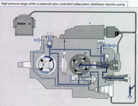
Although this diagram shows a four lobe HP pump, I am sure it's operation is the same as our beloved VP-44. It's a little difficult to see, but if you look closely, you'll see three different shades of blue. The dark blue is the high pressure Pump out to the injectors; the medium blue is downstream of the internal pump (about 14 PSI mostly controlled by the overflow valve); the light blue on the left is from the lift pump. As you see, there are a lot more solenoids, valves, etc it there which are controlled by electrical signals and medium pressure. There is also a relief valve bypassing the LP pump back to it's inlet if pressure gets too high. The overflow valve is shown on the far right. I'm not too sure where the famous (infamous) diaphragm lives; I'll have to do a little more looking. It's been a couple of years since I really dug into this. I'll see what else I can find that might be of help. humbly jimmy
-
I guess what I'm saying is that the internal low-pressure pump is between the inlet port and just about everything else in the VP. I believe (I love that word) it's purpose, along with the overflow valve, is to maintain a fairly constant pressure (with adequate flow) on the inlet to the high-pressure pump. I guess I'm also saying that the inlet pressure doesn't make any difference as long as it maintains adequate flow to the injection pump. To do this, adequate pressure on the inlet must be maintained (FSM says 10 pounds, I'll go along with that). We also know that too little pressure to the VP can cause diaphragm damage and make for hard starting, as well as other bad things. We also know that too much inlet pressure is also not good for the pump (causes hard starts, etc). Jimmy

-
This is a very interesting thread. It's good to see so many minds at work. Just to add another thought into this, I believe we are all overlooking some of the design of the VP44~~like the internal low pressure pump INSIDE the VP. By design, this pump should try to keep the pressure above the 14 psi set point of the overflow valve; thus, as long as there is adequate flow to the VP, the overflow valve will always be open somewhat to maintain the 14 PSI. I believe (there's that word again), the 10 PSI minimum suggested by the FSM is to ensure adequate flow, mostly through the overflow valve, to cool and lubricate the VP. Looking at the picture of the VP, it looks like the overflow valve is very near the inlet fuel inlet; in reality, as far as operation of the VP, it is actually in another chamber downstream of the internal low pressure pump.Just my thoughts.Jimmy