
Dodge48
Monthly Subscription
-
Joined
-
Last visited
Everything posted by Dodge48
-
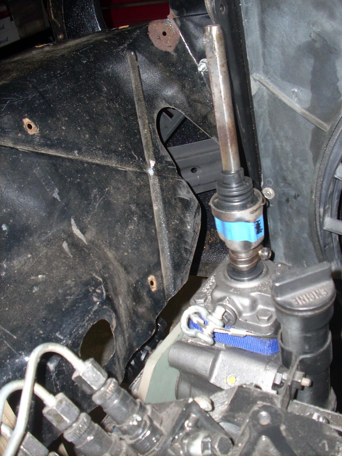
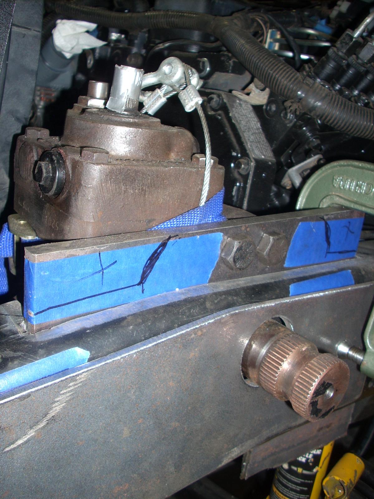
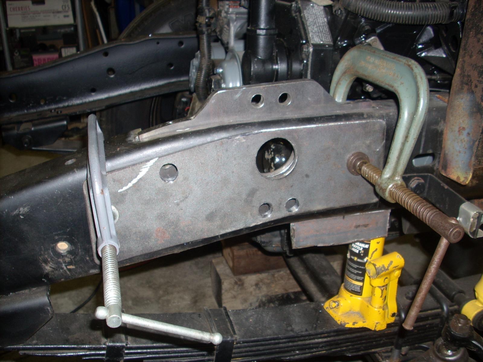
Thanks again. You obviously have your priorities in the right order, well being of the family first. I'm an older guy, kids are long on there own, if it wasn't for my "projects" I don't know what I'd do. I think I'm a subscriber to the forum now so I'll try to post the pictures for "Part 10 "Steering".

.JPG.5d1611fdb512f9e5e34c48c18fbc3ddc.JPG)
.JPG.d42b6617a6a7f770271f03912ccf2366.JPG)
.JPG.af972665e9443bd28b7ba216f0d1de80.JPG)
-
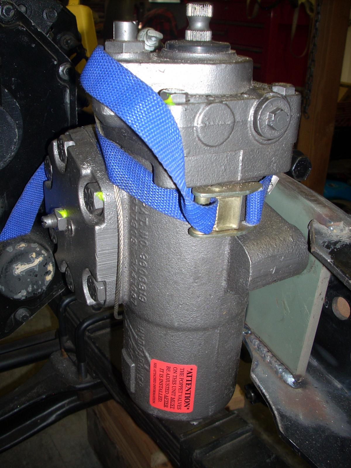
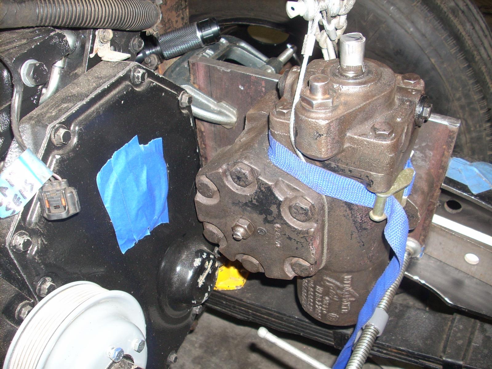
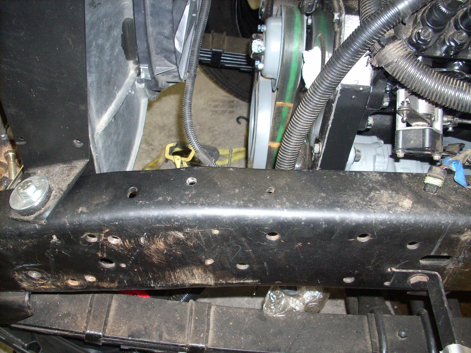
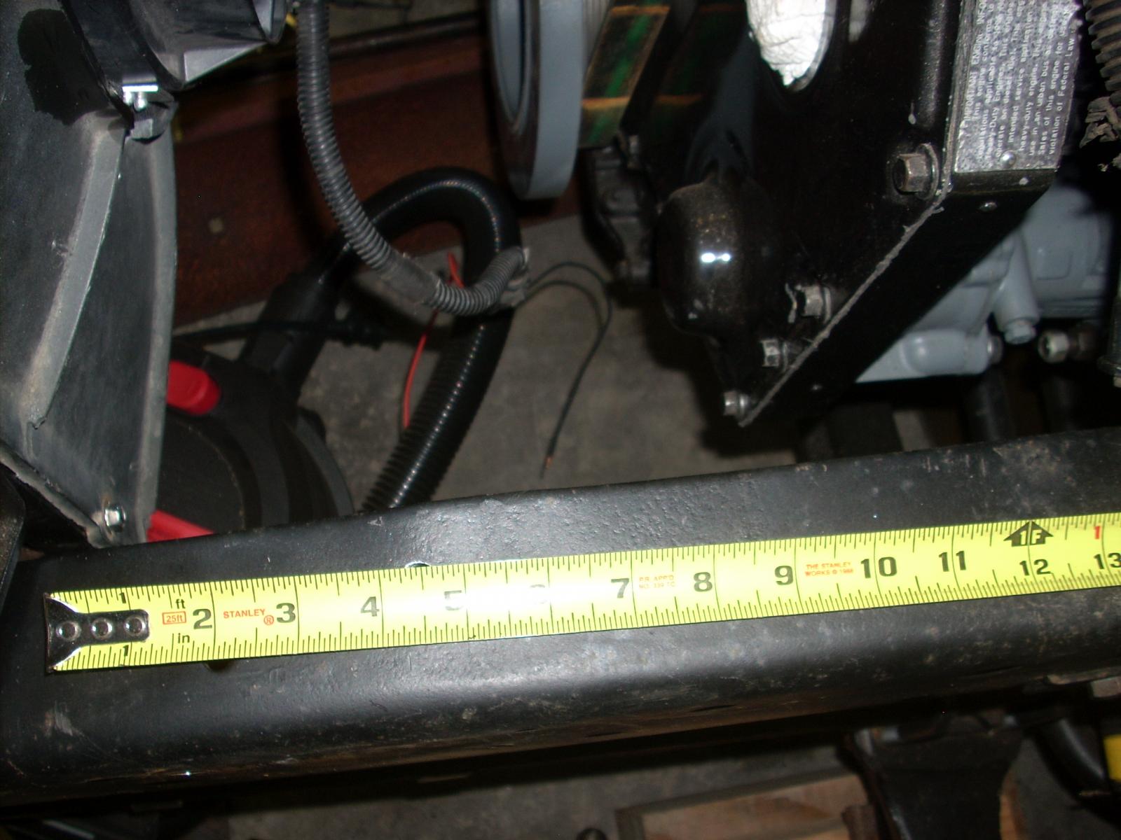
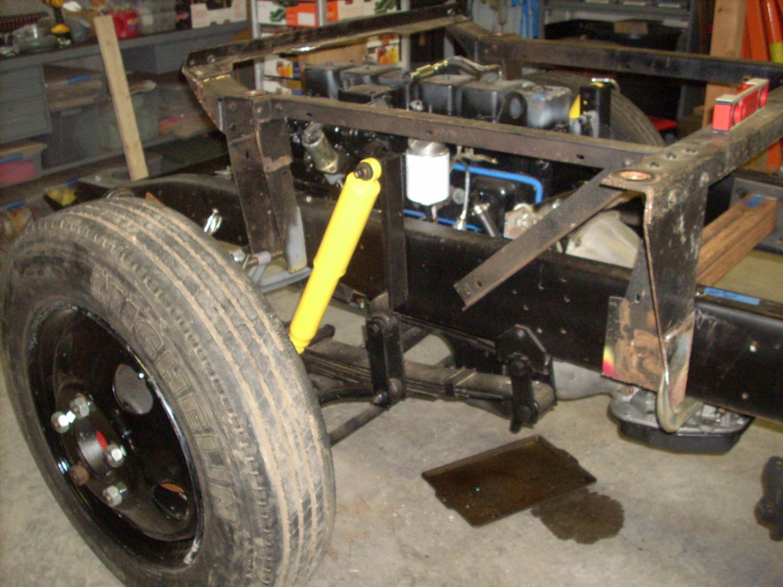
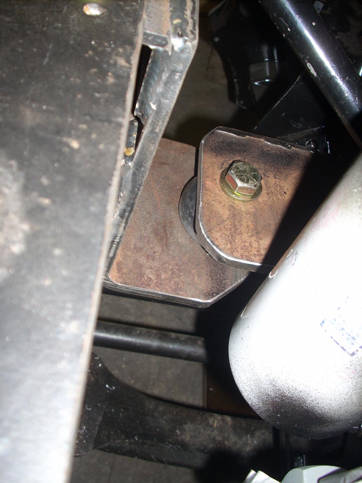
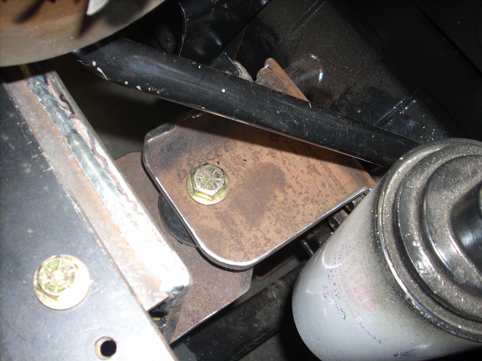
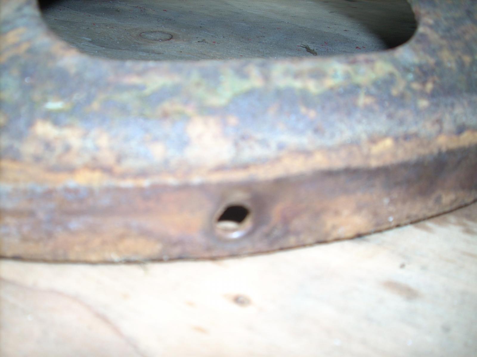
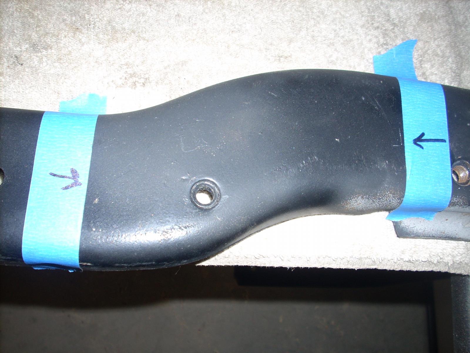
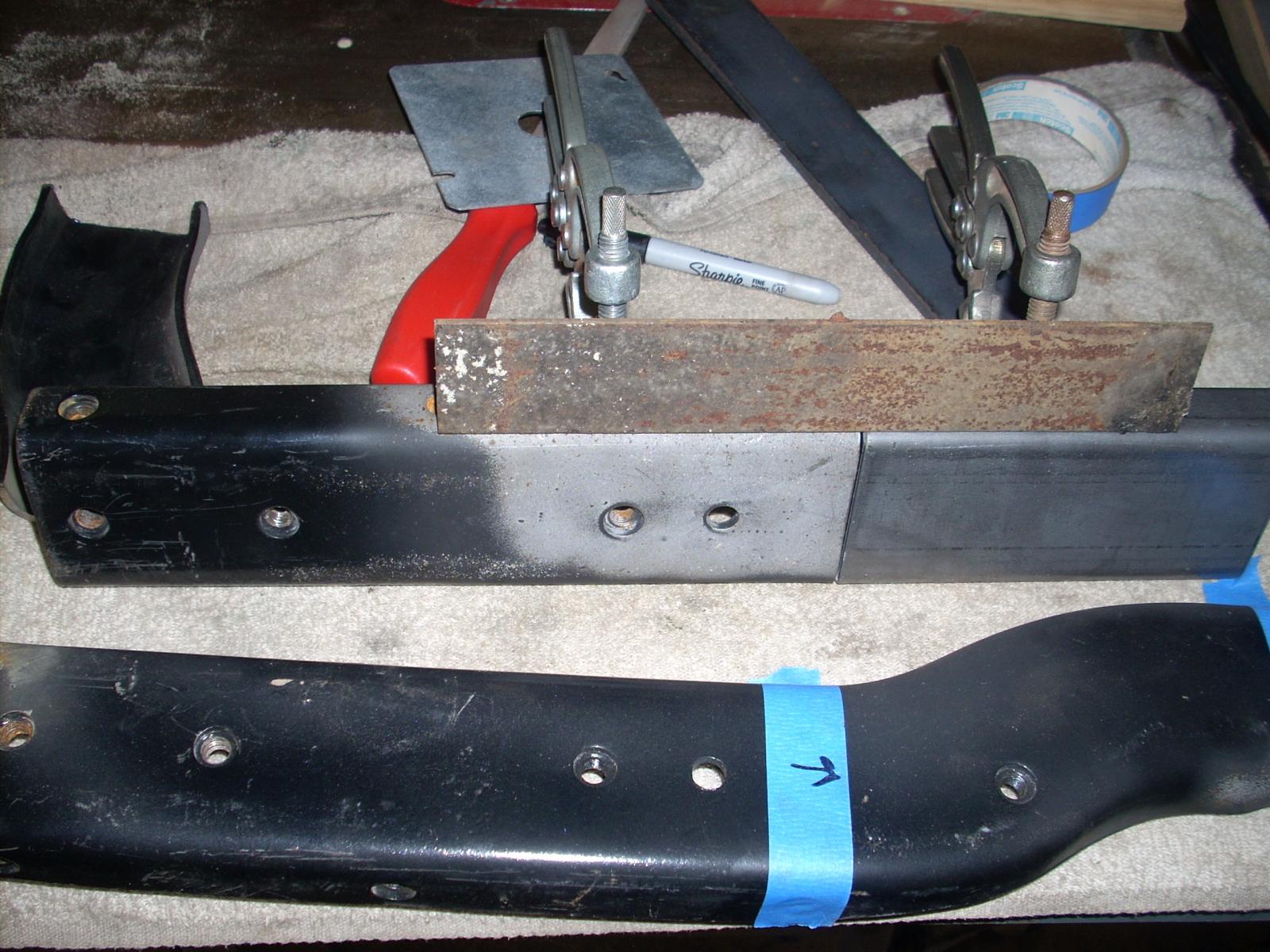
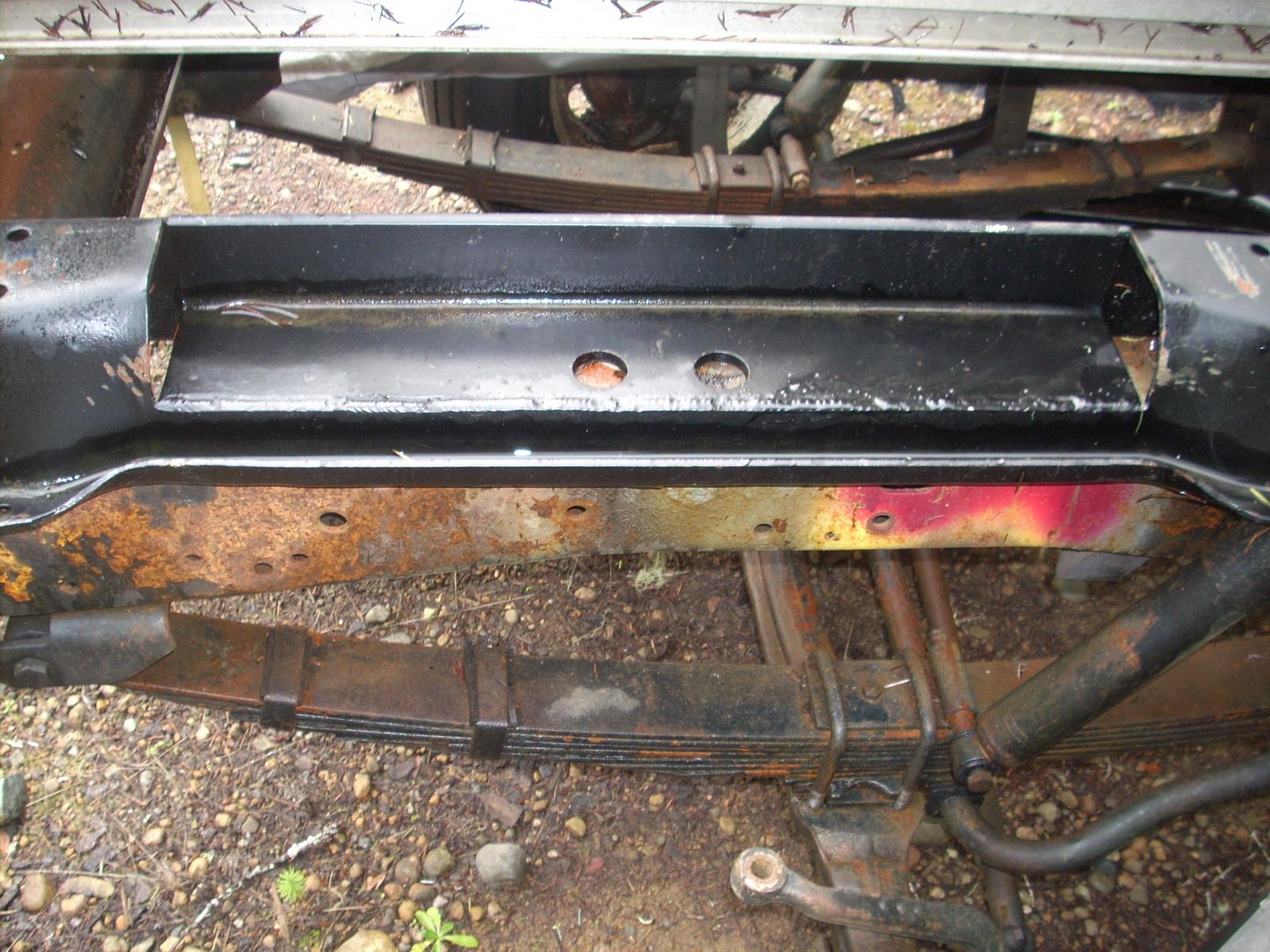
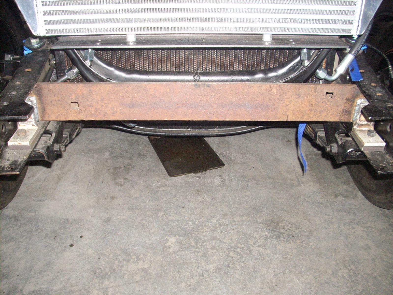
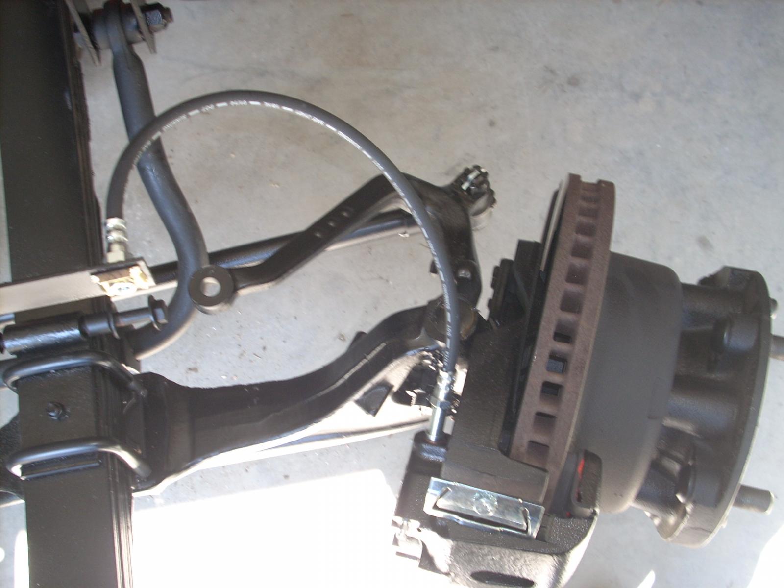
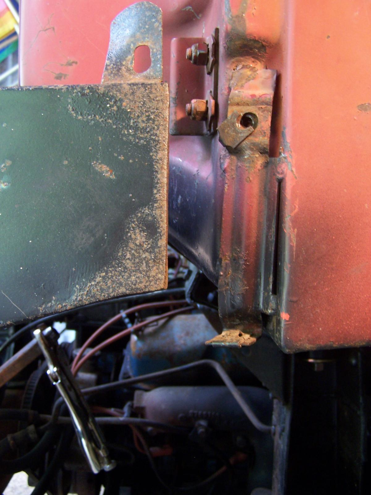
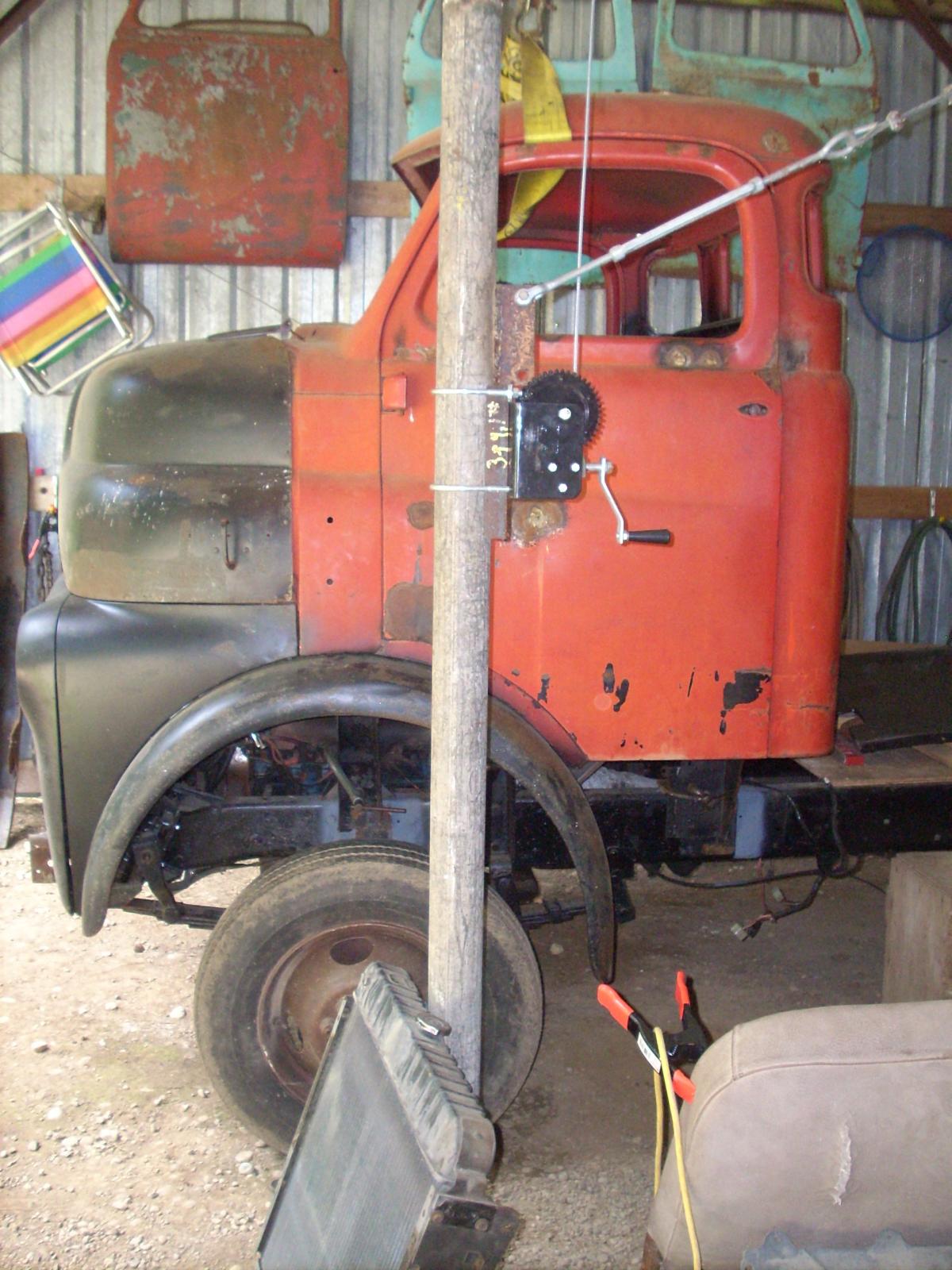
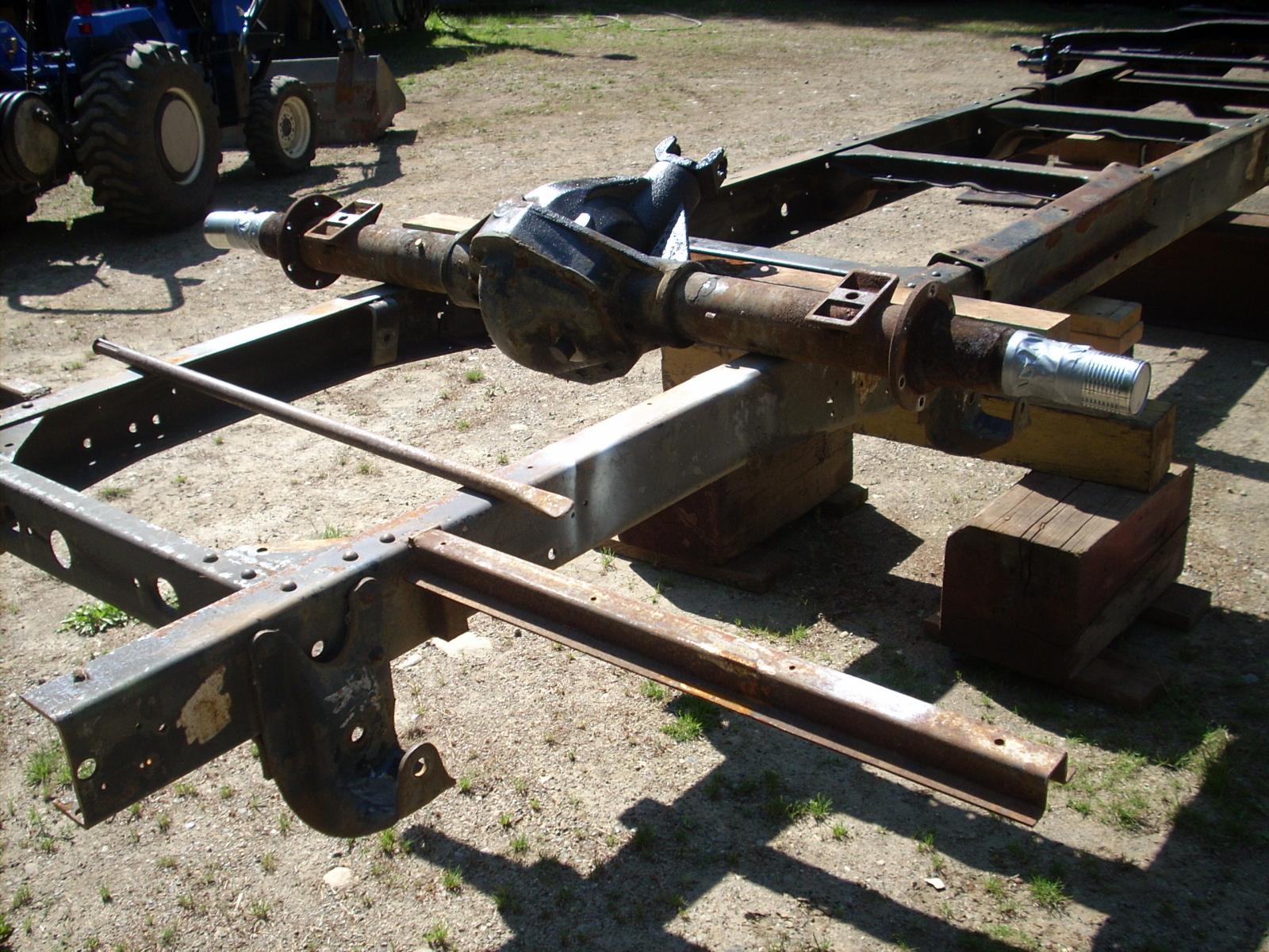
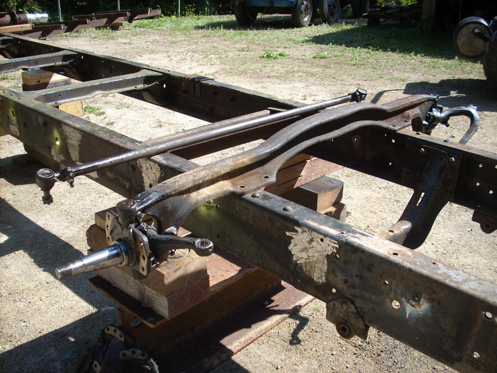
Timd32. Thanks for your research of the Haden 48 Dodge COE owners; great job, you should be a detective. I contacted the Hayden company a couple of days ago; the person I needed to speak with was not available, we'll talk next week. Thanks again. Part 10: Again it has been awhile since I posted, life gets complicated; I hope you haven't lost interest. I'm going to present what to-date has been one of the most difficult of the modifications I've had to address-steering. As might be obvious to some, the MH chassis had the steering gear set out from the left frame rail by about 15 inches and just behind the front panel of the coach. I removed the framework for the steering box and hydro-boost brake system and intended to mount the Saginaw box forward of the driver front wheel and on the outside of the frame rail. This became a "big deal"; no matter what I tried I had significant wheel and draglink interference. I tried several attempts to fabricate different brackets to accomplish an acceptable result - no luck; no matter what I came up with I ran into the driver wheel coming into contact with the steering box; and, the draglink was totally out of alignment with the pitman arm and the driver side wheel control arm. I tried several of the Seattle/Tacoma "specialty" steering shops without resolution; I met some nice people but they were not into "fabrication"; if you gave them year, make, and model they could help you with an off the shelf item - no luck. Then came the internet search; after many calls I made a find, Mark Mason at Straight-line Steering in San Jose, CA. Mark took the time to listen to my problem, I sent pictures and in a few days he had a proposal, if I paid the freight he would send me an HFB52 series steering gear from an early 60's Ford (I think) to establish fitment. It is a box that sits vertically and is integrated with a hydro-boost system which I was already planning to use in my brake system. After determining it would fit I decided to take the leap and make the frame modifications to accommodate the HFB. The HFB has a trunnion shaft that extends through the chassis rail and to which the pitman arm is attached. Since cutting into the flanges of the chassis rail would weaken the chassis and given the forces that would be substantial given the location of the HFB I fabricated a modification to" stiffen" things up (I am lucky to have a young man who is an accomplished welder and a retired machinist from the local naval shipyard to assist me). Finding a pitman arm with sufficient length to work with the hub steering geometry was the next challenge; again Mark came through with an 11 inch pitman arm with the required off-set, and the machinist turned out a drag-link - it all lined up. I'm going to attempt importing pictures that give a little better understanding of the above. Hope you found this interesting, Jim For some reason I cannot insert pictures, I'll try to find out why.
-
I can't in any way address your stated problem. I likely going to show my lack of knowledge on transmissions on the Gen II Cummins. I have a build going on which is posted on this site; I am approaching the time I have to get serious about hooking up a wiring harness to my 2WD 47RE transmission. I thought The 4x4 12V Cummins used 47RH transmissions, am I wrong? I thought the big difference between the 47RE and 47RH (other than the output for the transfer case) was that the 47RH is vacuum controlled and the 47RE is electronic controlled; am I wrong? MnTom, good luck on figuring out your problem, I'll be watching.
-
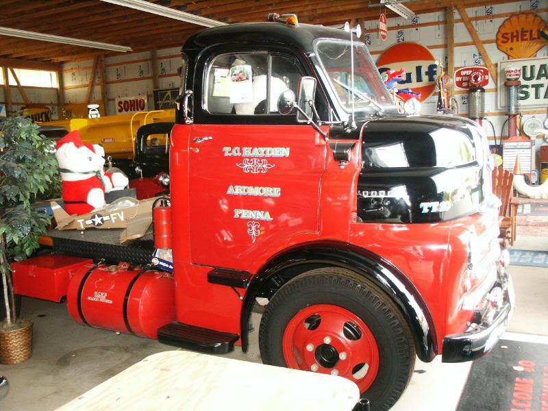
dave110, to make it clear, the pictures are not my project (I only wish). I tried to run down the owner (no pun intended), not sure how old the pictures are, I think old. If you notice, the abbreviation for Pennsylvania is the old format as opposed to what we have used for the past 20 years or so, PA (I lose track of the years). I made several phone calls to people in the area of Ardmore in hopes of connecting with the owner - no luck, but I use it as a benchmark for what I hope to have when my project is finished. Thanks for looking. Jim


-
Brent, thanks for following thru with contact. Yes, I was on the other site and still visit; just seemed like this site was a better fit for my particular build; the area I'm having issues with is the Cummins interface. In particular my "issues" are with the wiring harness to support a 2WD 47RE transmission (haven't gotten to that issue yet on this site). I think I've said before, all I have posted here is earlier work, I'm getting close to my current efforts (right now I'm working on HP tubing/hoses for the Hydro-boost system steering). To your purchase, looks like a good base to start with, what are your plans, stock or mechanical upgrades (please don't slam)? Where are you in OR? I have a daughter in Lake Oswego and friends in Silverton (where I grew up); I'd be fun to hook up. A couple of pics of the goal. Jim

-
PH2500: Depends on where in Oregon. I have friends pretty much everywhere except NW Oregon; but, I can travel. Thanks again. Jim
-
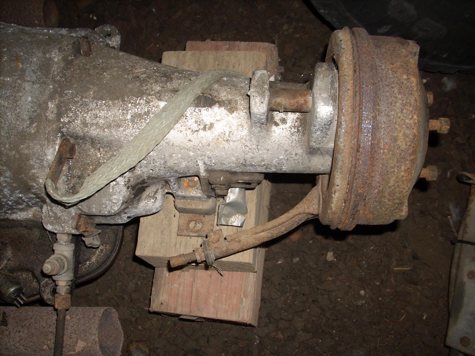
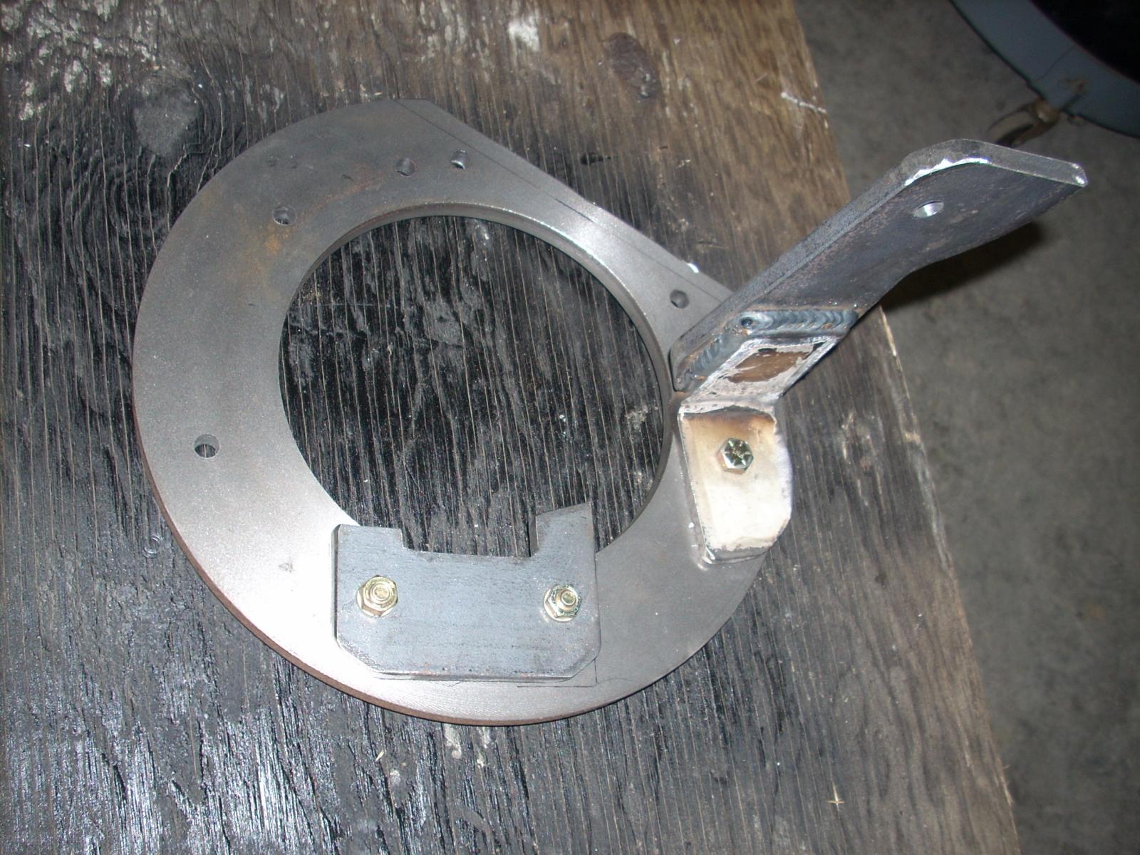
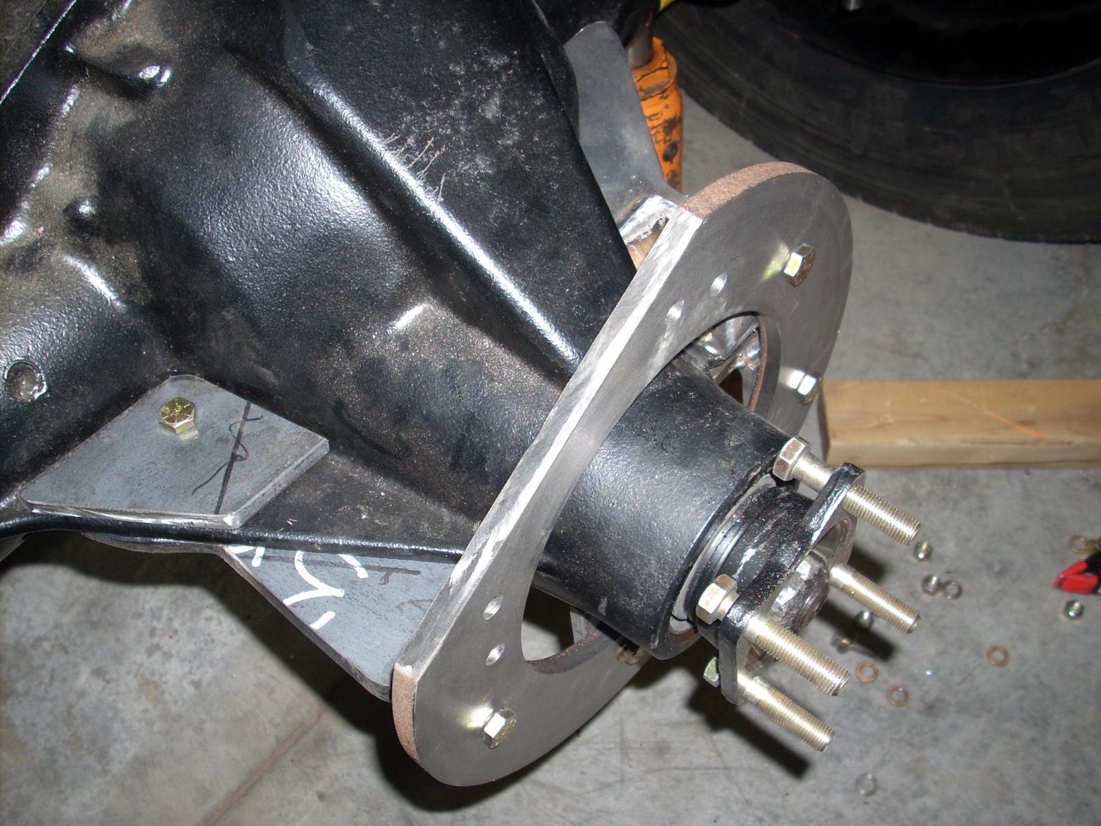
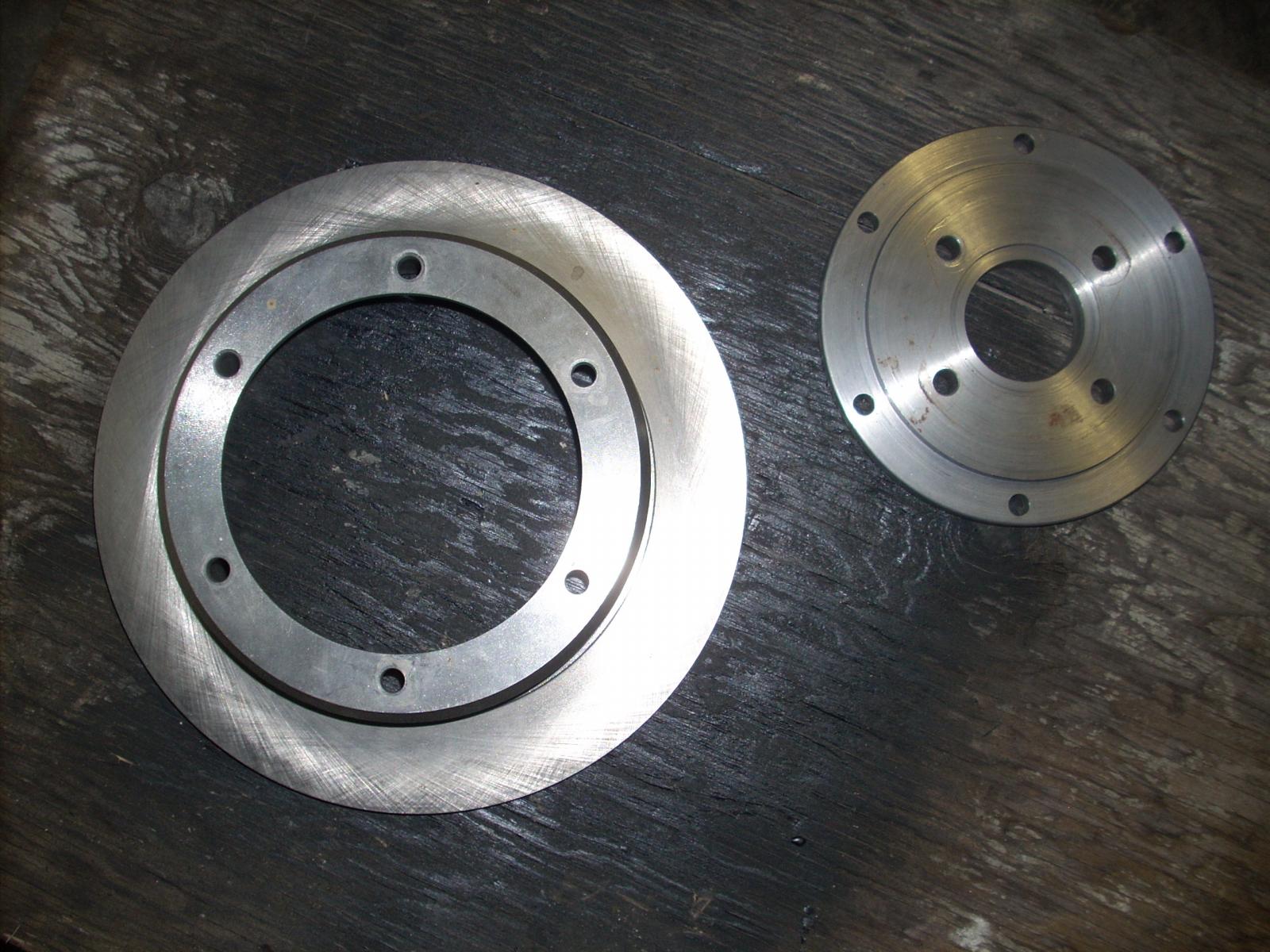
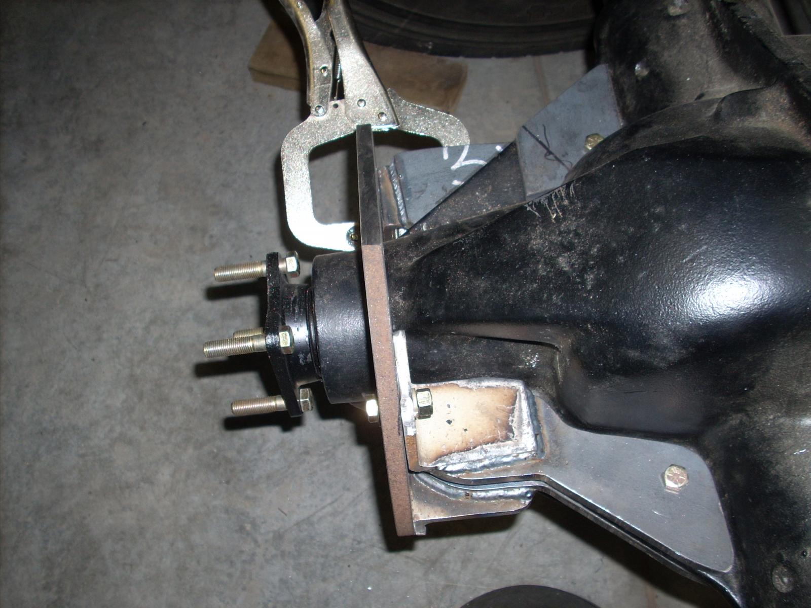
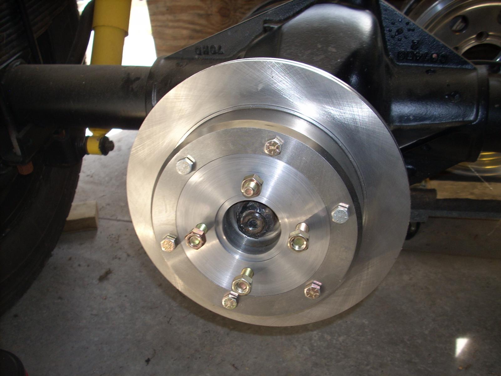
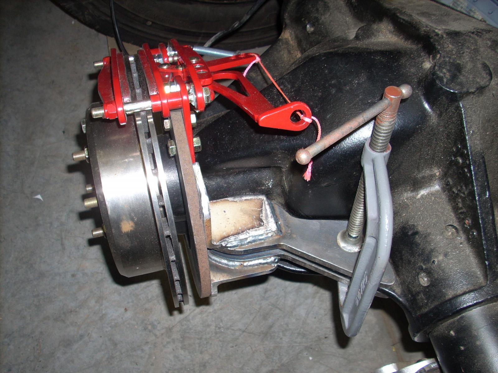
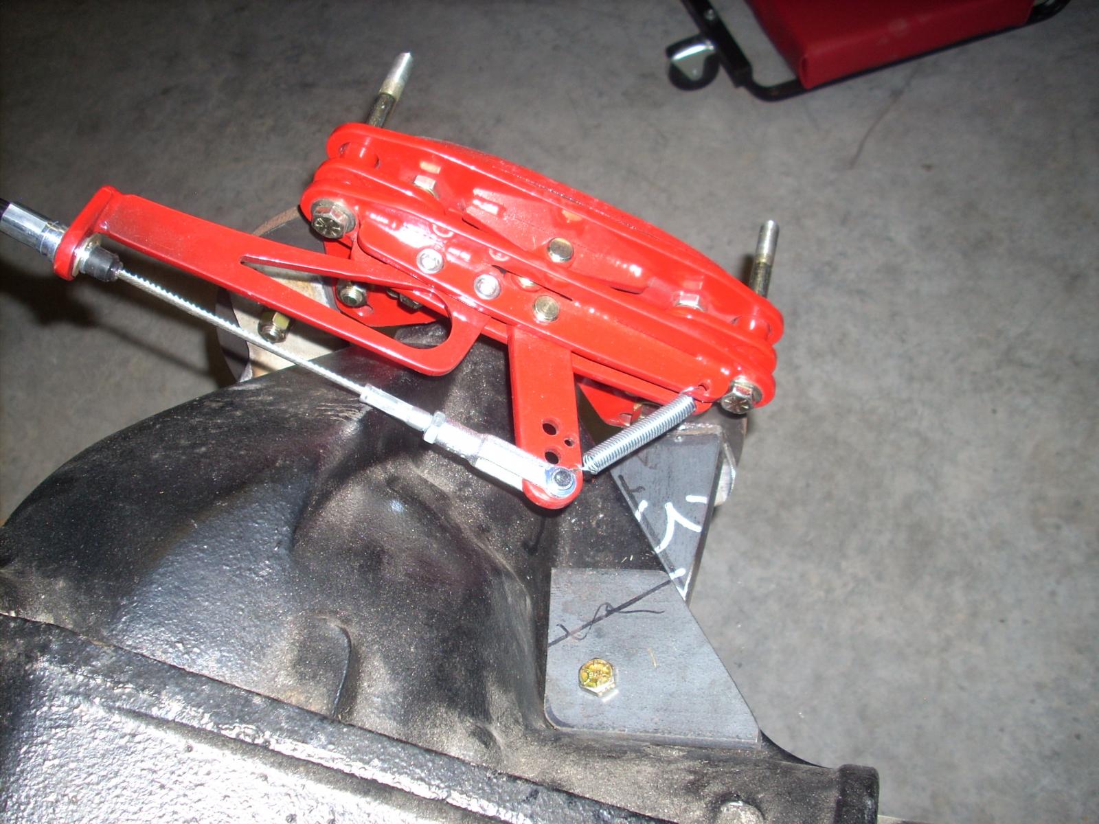
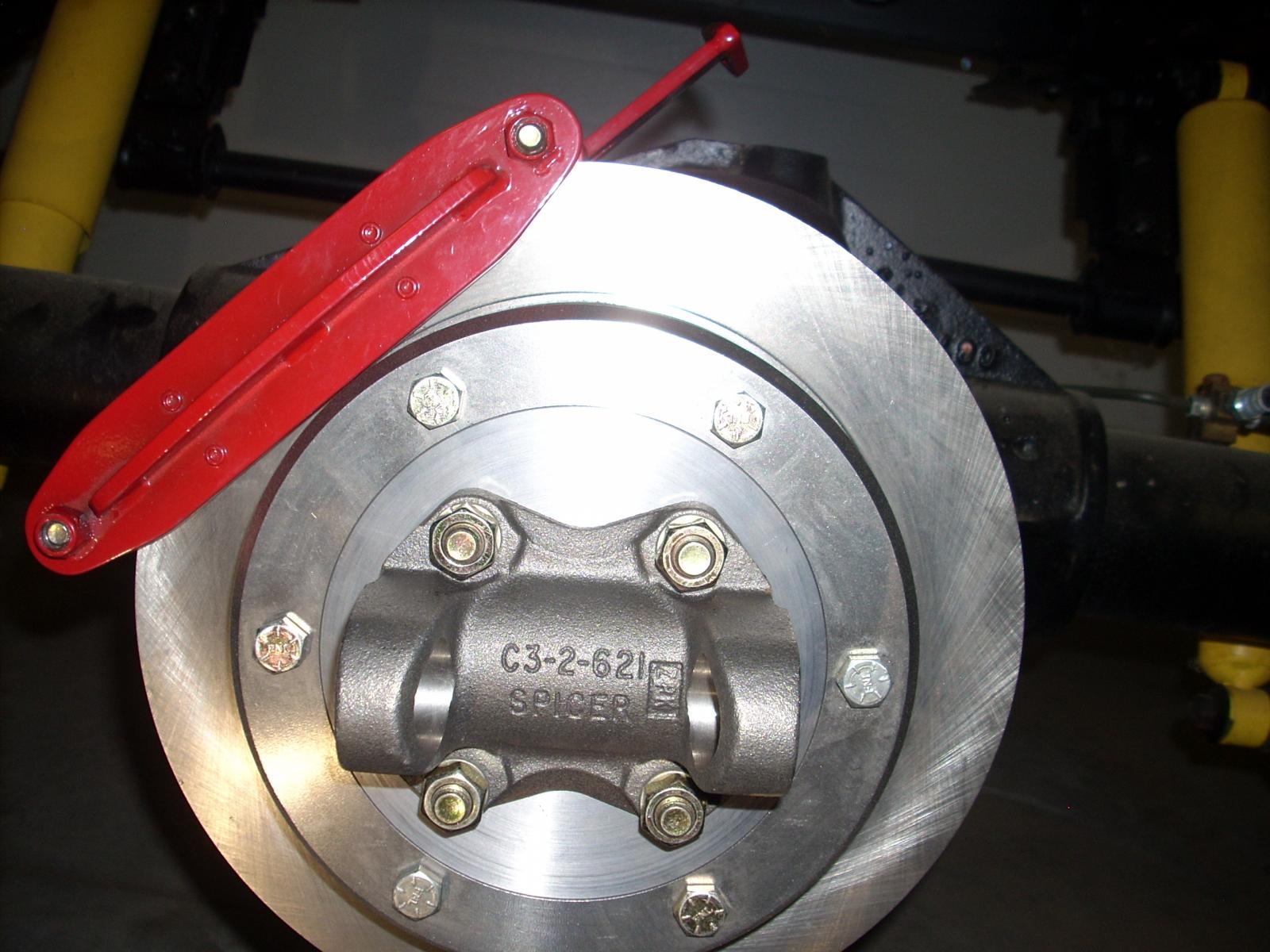
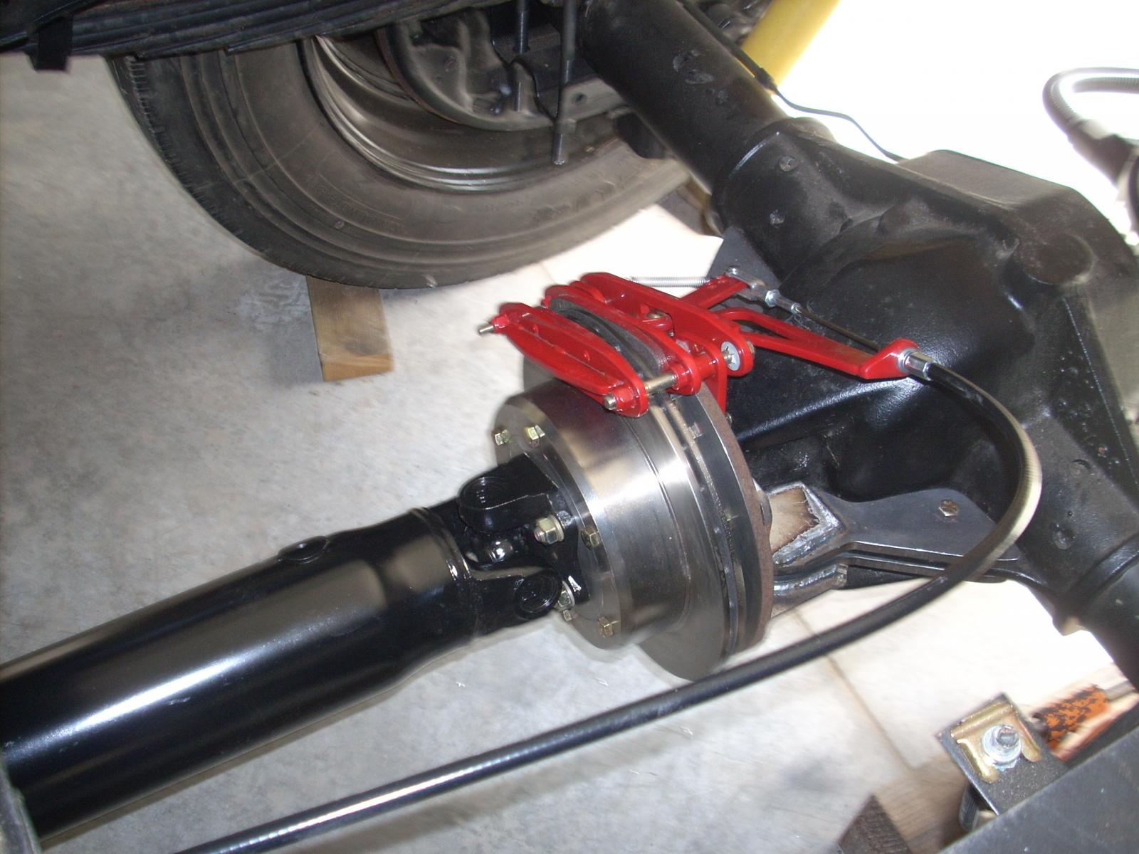
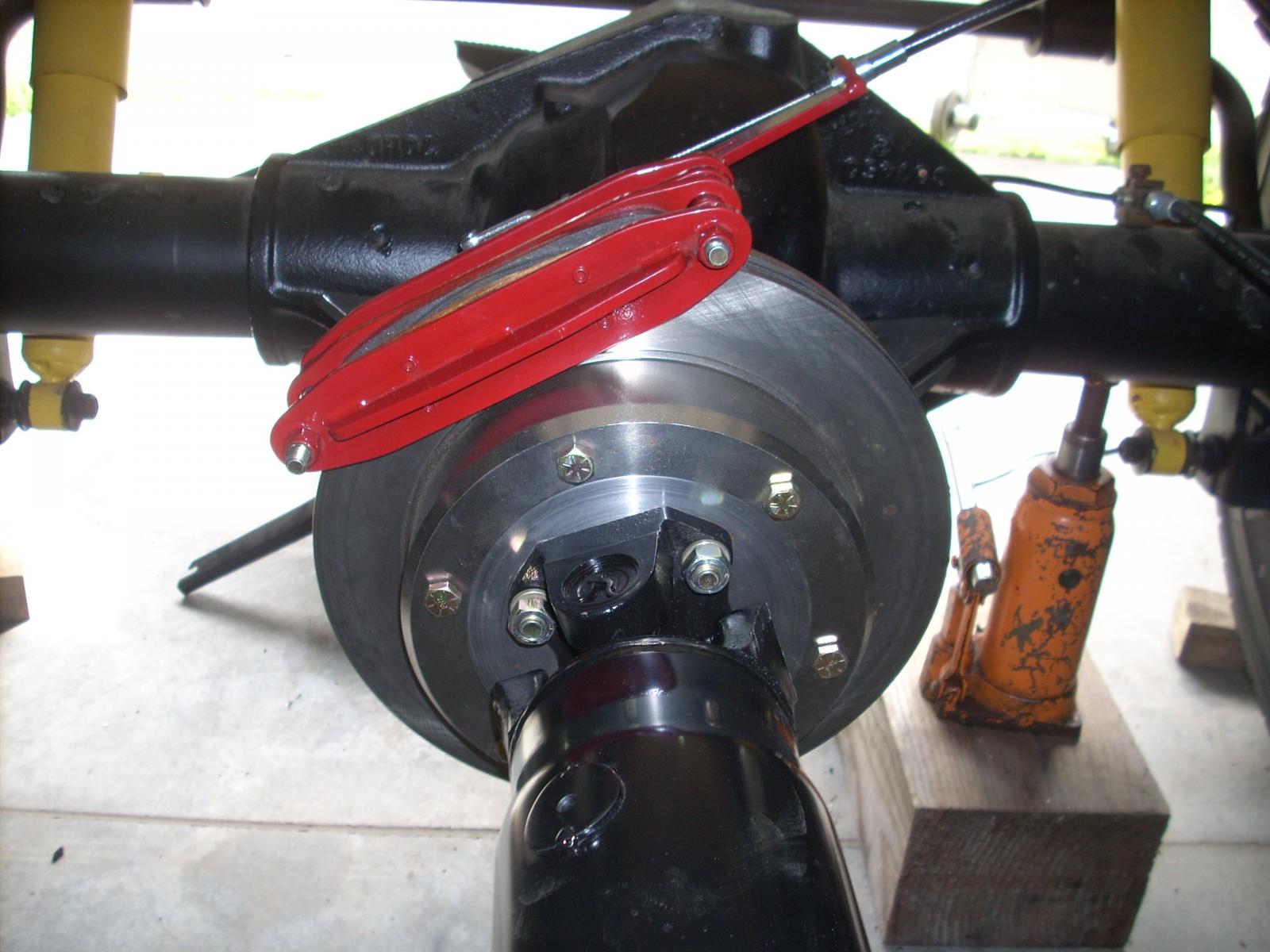
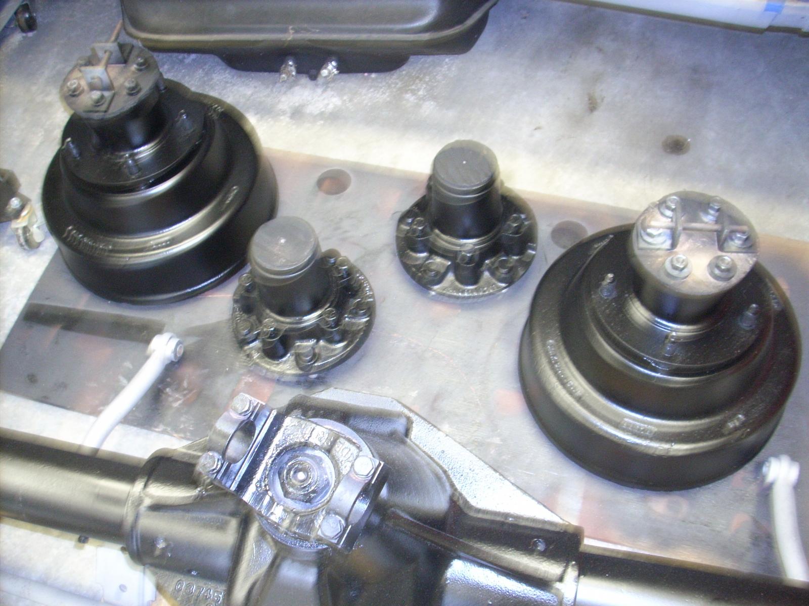
o1cummins4ever: Thanks for the encouragement. PH2500: I do not know Brent, sounds like someone I'd like to know; can you hook us up? Part 9: Last post showed a couple of shots of installing the 47RE 2WD transmission; this turned out to have consequences that I really hadn't given much thought to. The original 440727 combination had a parking brake which was integral to the tail-shaft; the 47RE has no such casting nor was it obvious to me how a parking brake could be adapted for that location (bare in mind, I'm no expert on any of this stuff that I'm doing). After considerable thought, and discussions with friends on the options I decided to fabricate a parking brake on the input shaft of the differential. The books at the local NAPA store were not very helpful, I had a minds eye to what I needed but I had to "find" it. The store manager was kind enough to allow me into the "rotor" section and to open boxes until I found something to work with. I knew I was going to have to fabricate a "fixed" plate from which to build; I had an old Porsche rotor that was approximately the radius of the front rotor I found at NAPA. I found a company in Colorado (TSM I think) that specializes in "off-road" calipers and ordered their largest unit to include their cable to attach a future parking brake handle to; the caliper was a perfect match for the braking surface of the rotor I purchased from NAPA. The NAPA rotor, for lack of a better word had a "deep hat" which allowed the rotor to fit over the input case of the differential, this would allow better mounting for the fixed base (Porsche front rotor). I cut a section off of the Porsche rotor in order to allow better mounting conditions for the caliper. I had to find a different input flange for the differential (the original was for a U-joint which I couldn't use, I needed a "fixed" rotation for my new rotor, I had a machinist friend turn out a mounting plate that would center the rotor and allow attachment to the driveline rotating assembly. As a side note, the original driveline was a three unit assembly, the front shaft was only about a foot and a half long and supported by a carrier bearing, the same for the following two sections. You guessed it, a new driveline with a single carrier which required installing a new cross-member. Turned out to be a good thing, I found a cross-member out of a GM motorhome, fit perfectly and was fabricated in such a way to allow passage of an exhaust system (the Dodge cross-member did not have that feature and would have been a problem), more on this later. I'm now going to attach some photo's, I may have to do it in two separate posts given the restriction on the size of the media down-loads. Thanks again for your interest. Part 10: This is a continuation of Part 9, mostly to finish this segment of the build with some finishing pictures. I am also installing a "line-lock" system, not done yet.
-
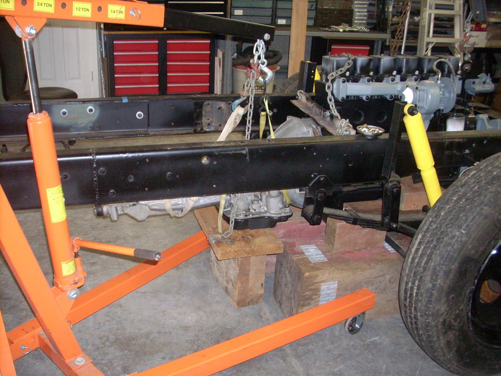
Part 8: It's been quite awhile since I last posted; combination of grandkids activities, weather (2 ft of snow that hung around for days and progress on the project which is pretty detailed. You probably noticed that most of what I've shared with you is steps taken quite a while ago, pretty much all of them are what I would call gross steps in the process; I've kind of worked myself into more detailed steps toward the finish - a long way to go - had I been candid with myself I'm not sure I would have taken on this project, I've got others in the wings. You know the old adage "in for a penny, in for a pound"; but, I'm lovin' it. In this segment I'm making the transition from an engine on blocks to slowly easing it into it's intended resting place (pretty tight), then attaching the 47RE transmission (no cross-member yet). A couple of the attached pictures show the cab support, the height of which must allow alignment with the core support which was addressed earlier (it all comes down to wheel opening be in a proper relationship with the wheel, both in center and space from the top of the tire to the highest edge of the fender). I'll try to be more consistent in my posts, I appreciate your interest and comments. I know I'm still not using the proper format for this, I've got to figure it out.
-
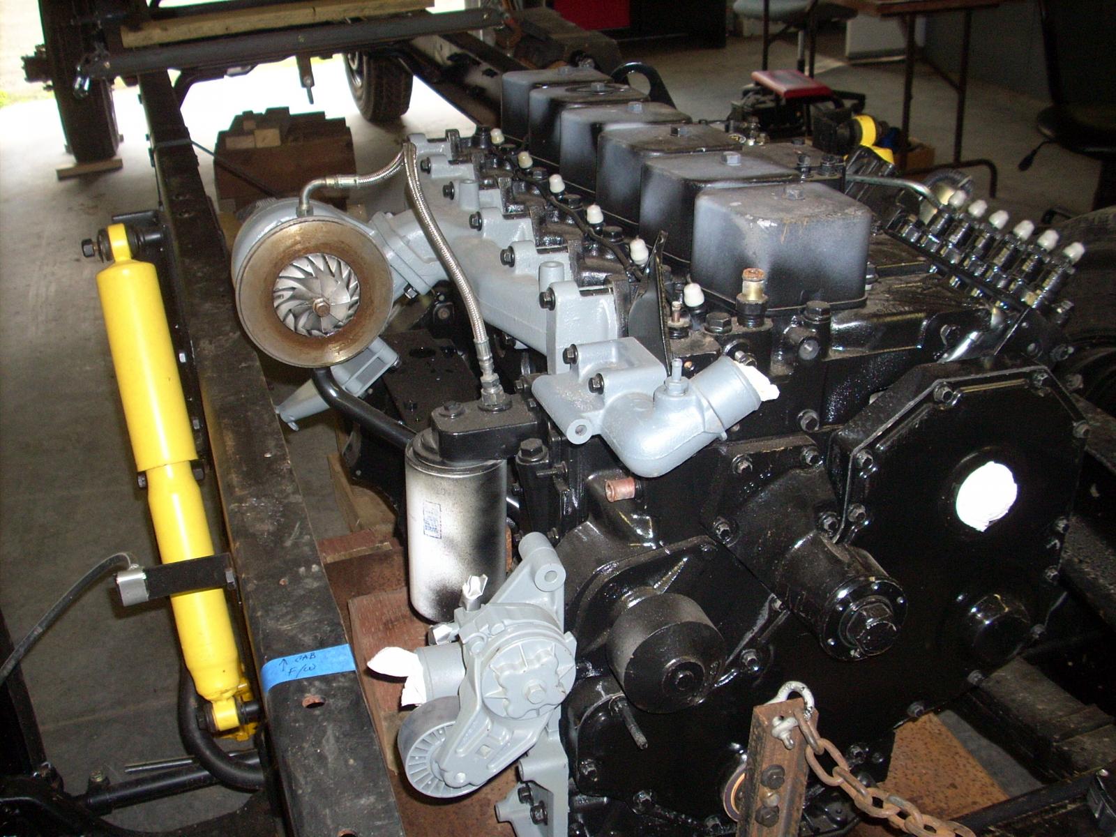
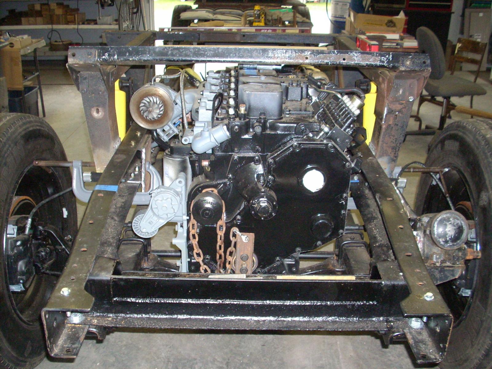
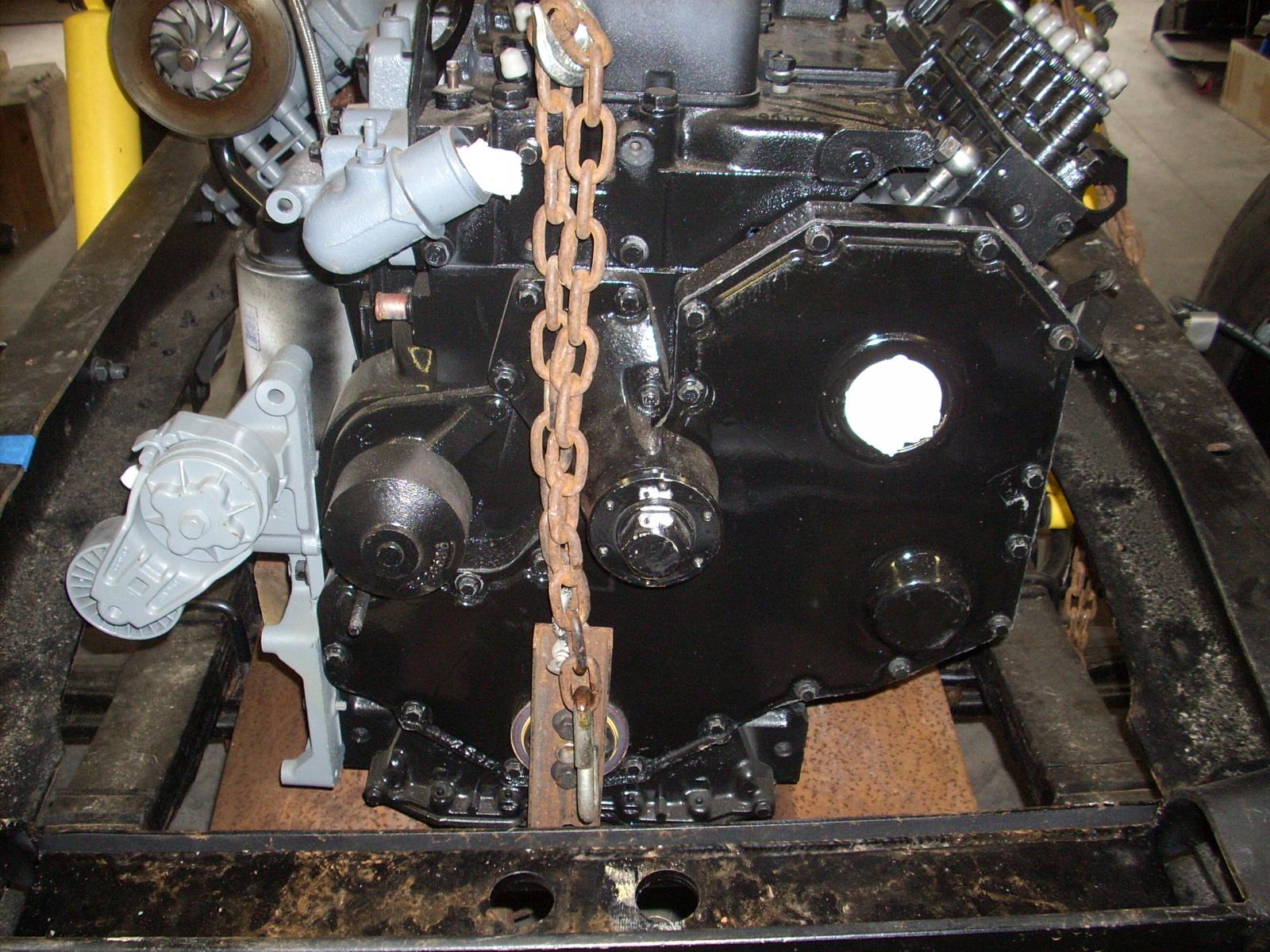
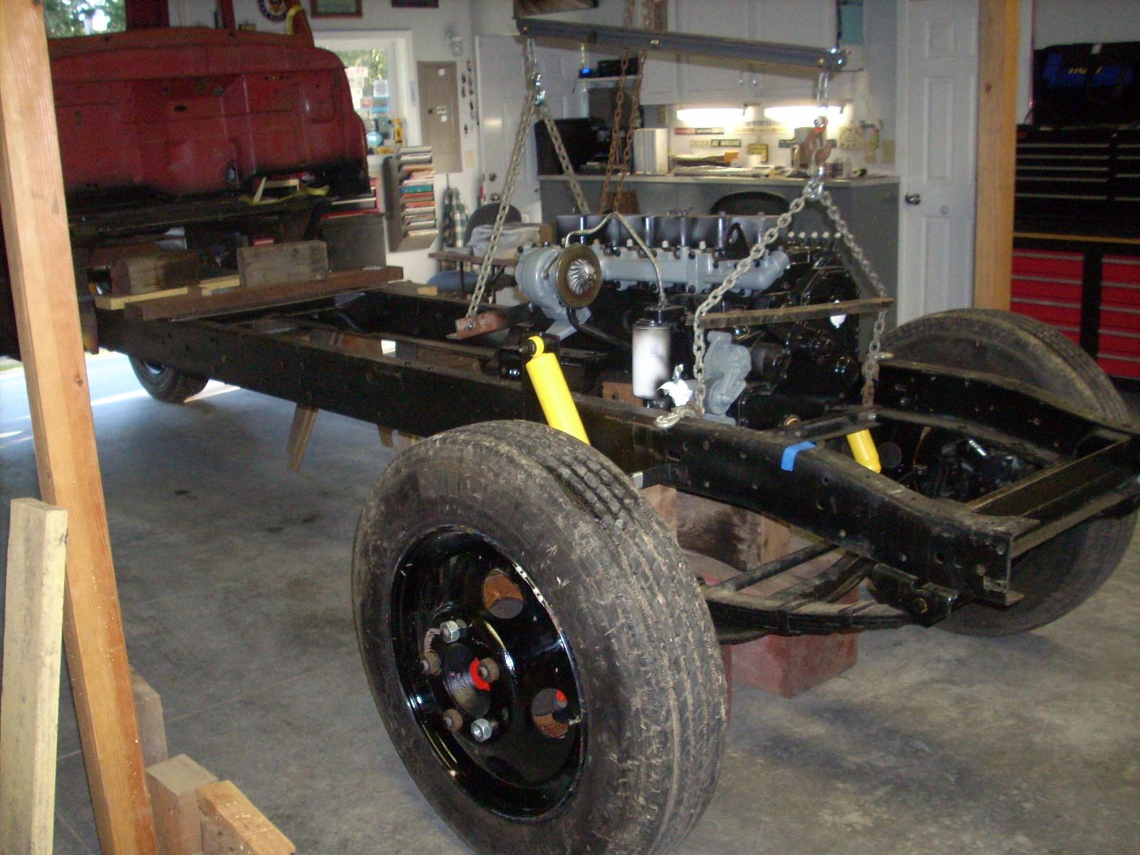
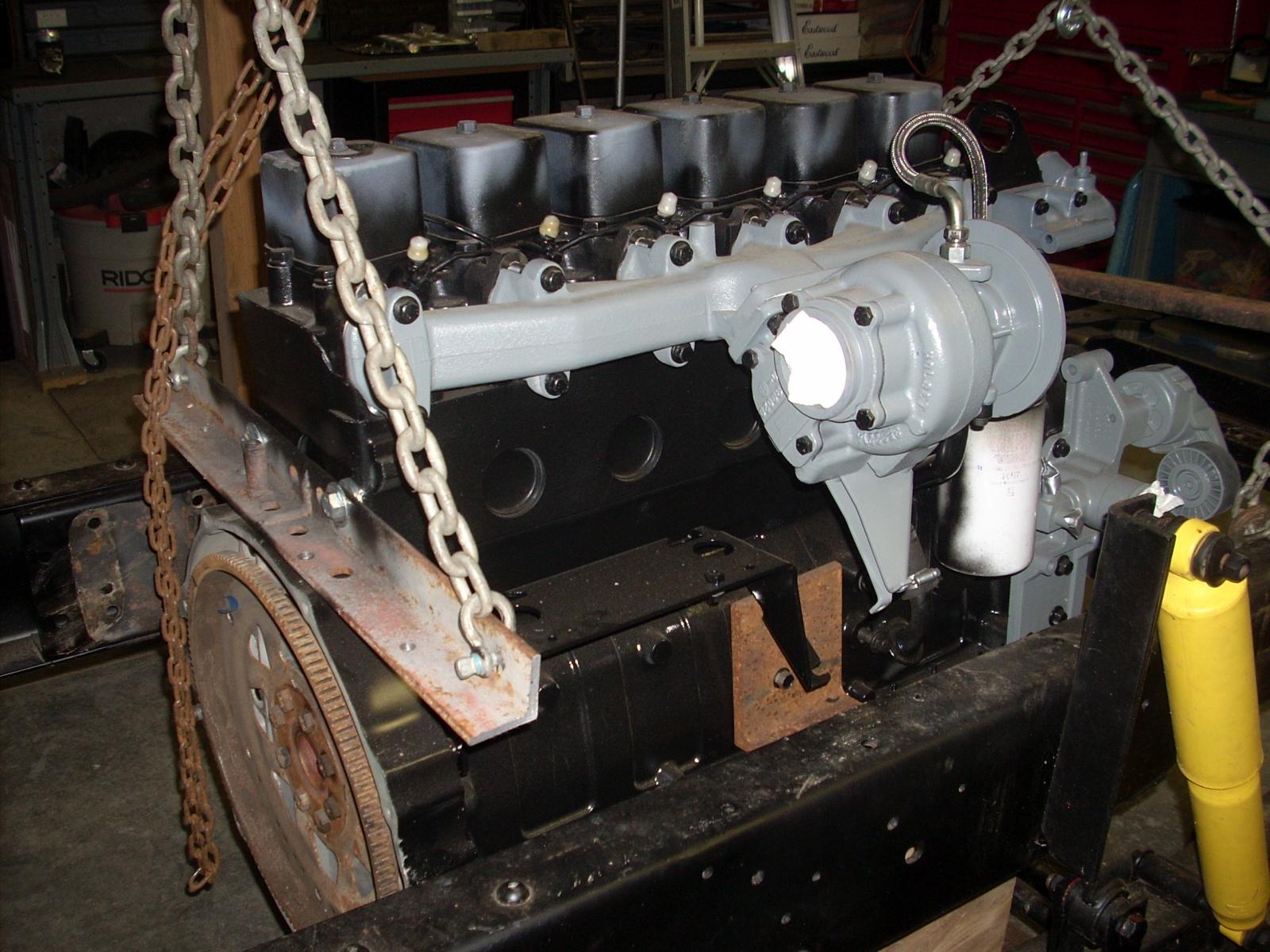
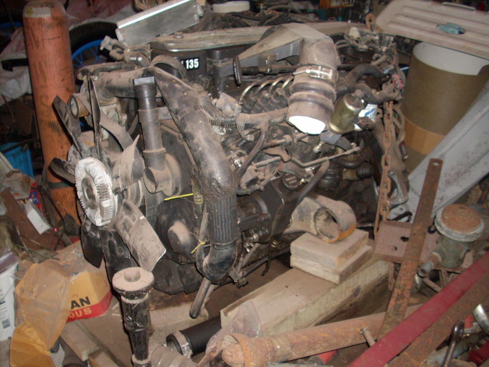
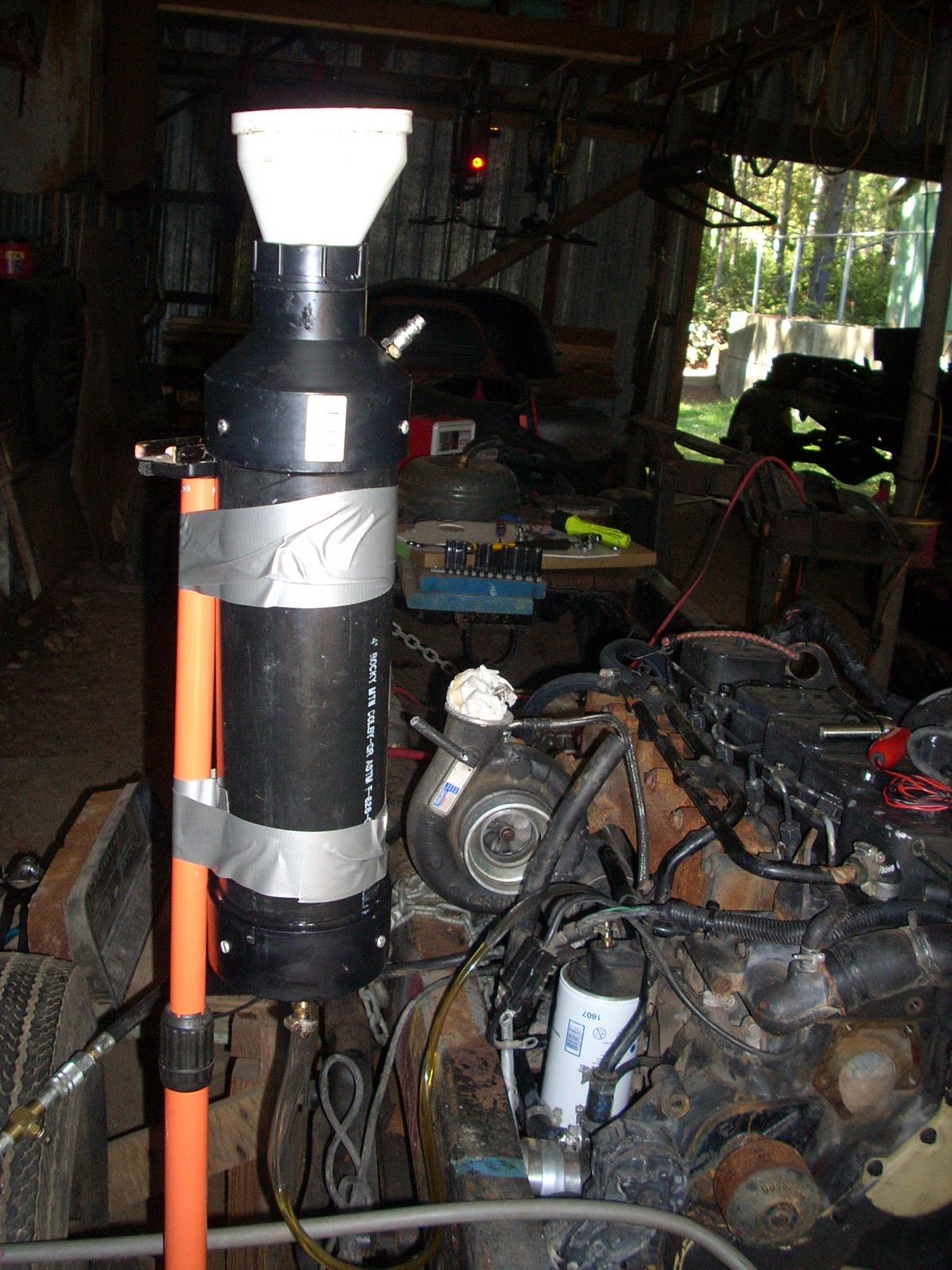
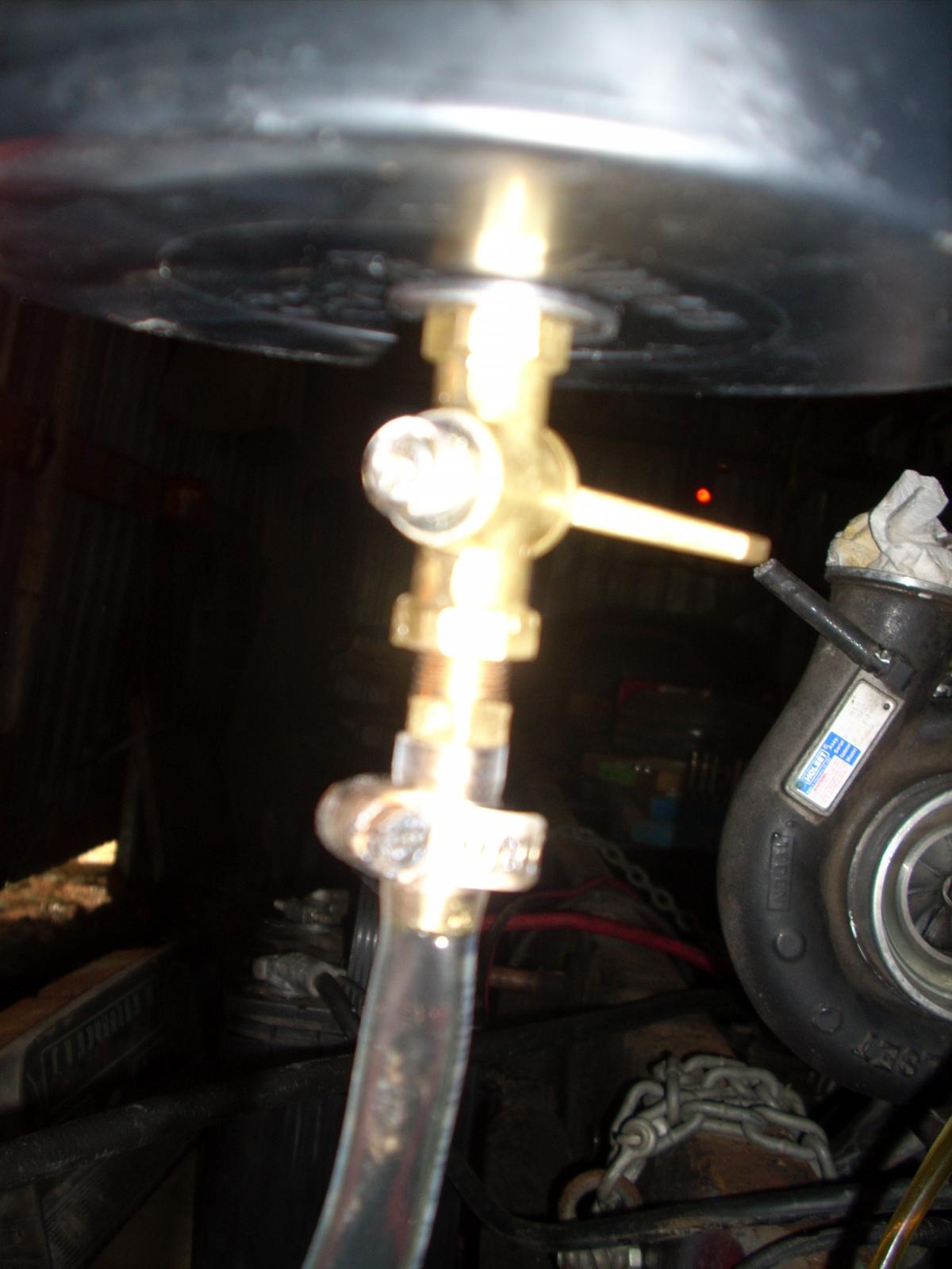
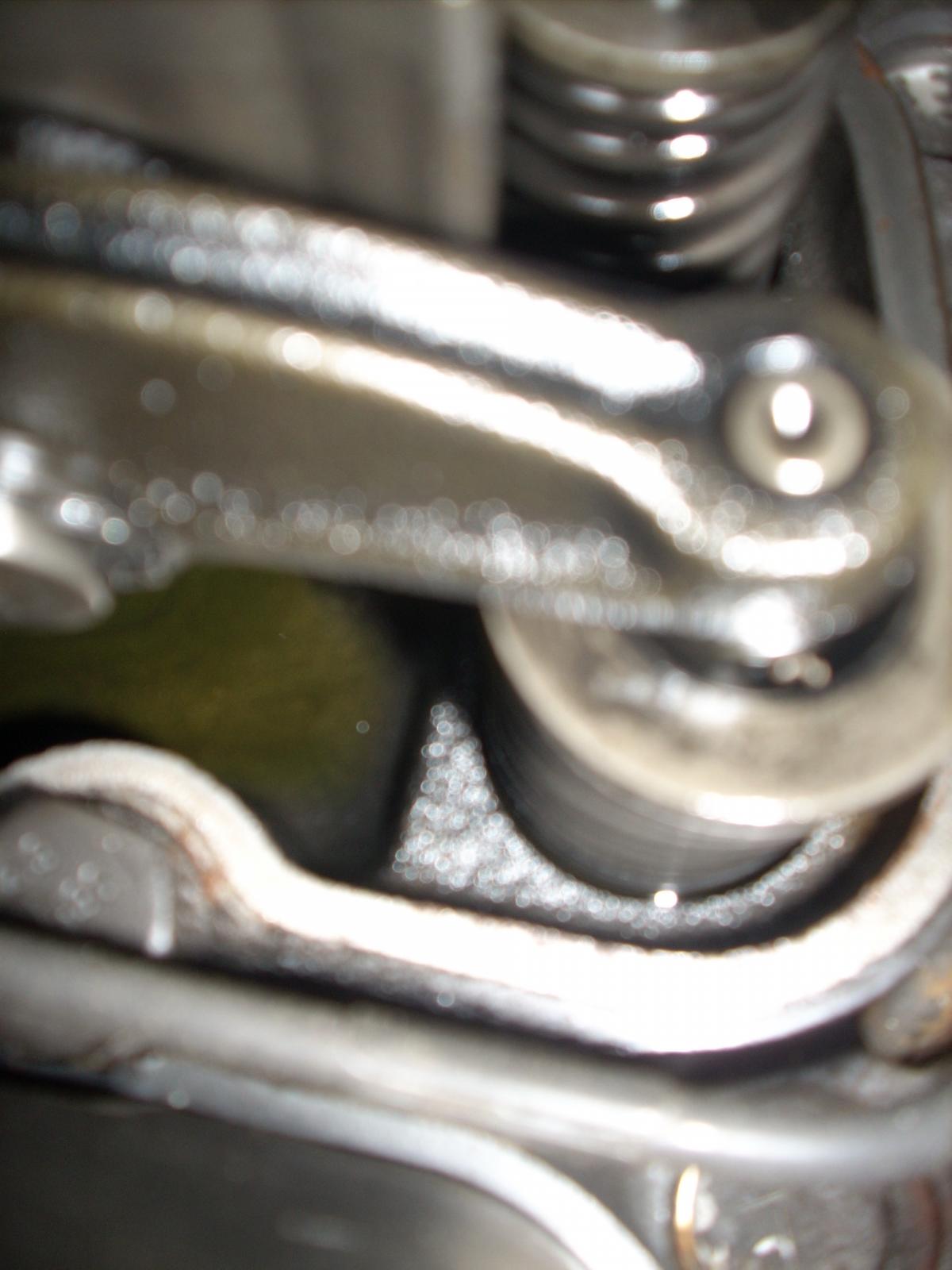
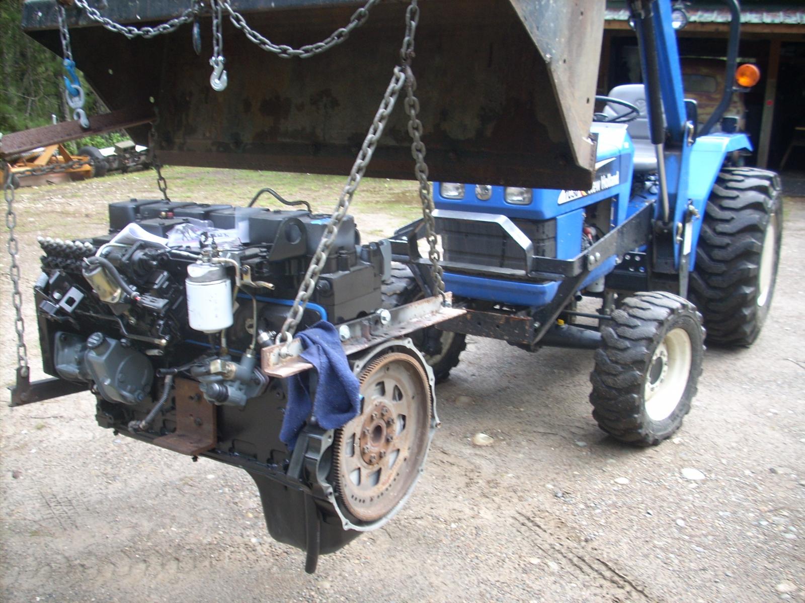
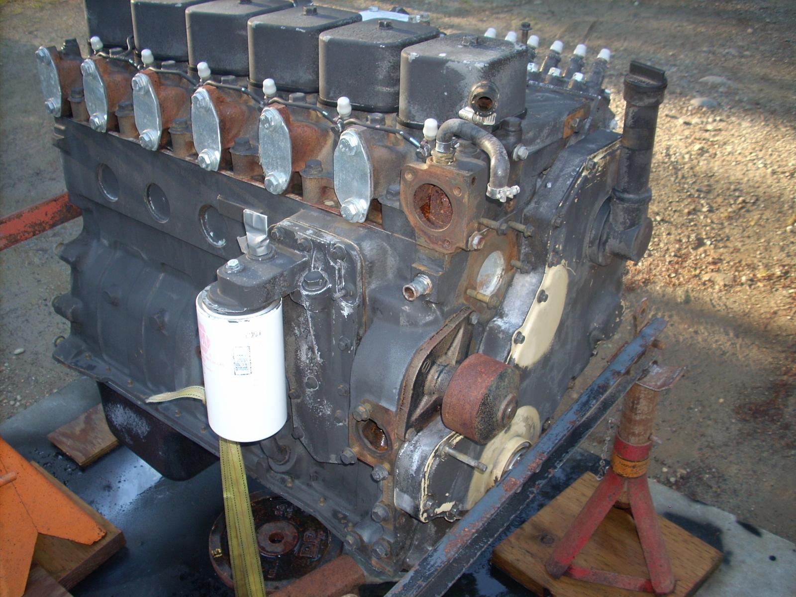
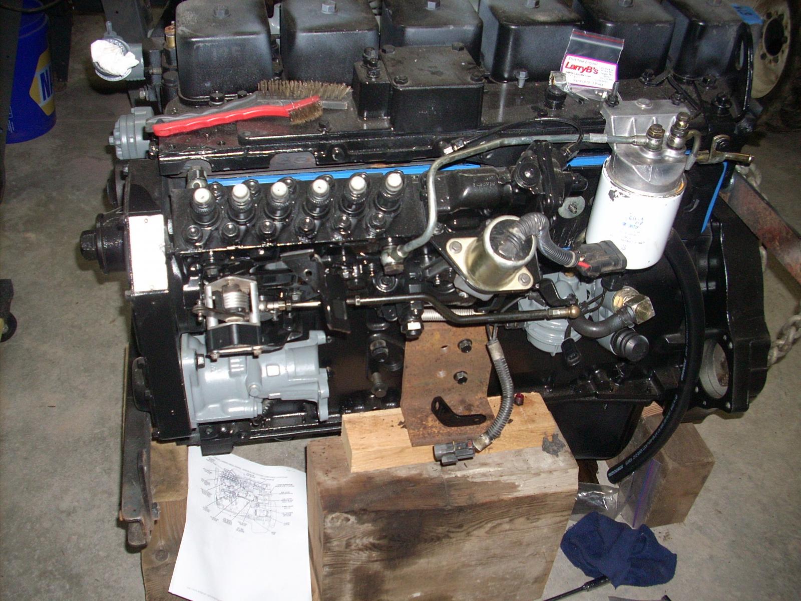
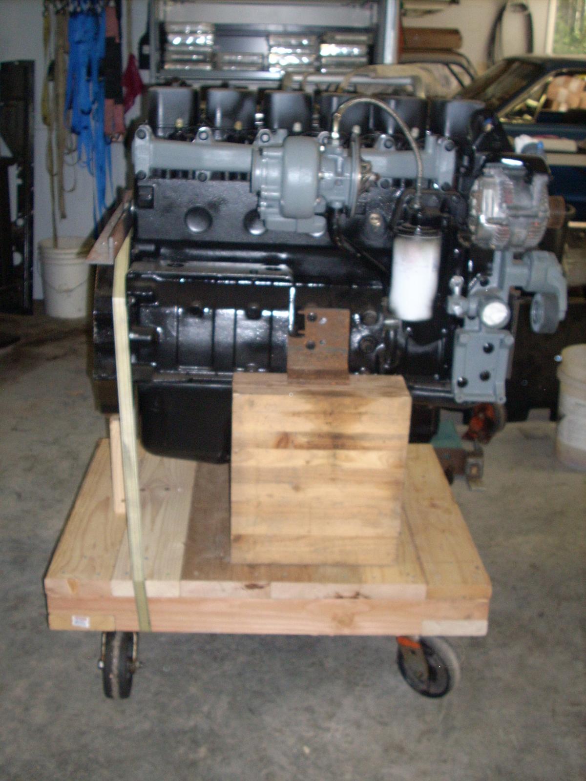
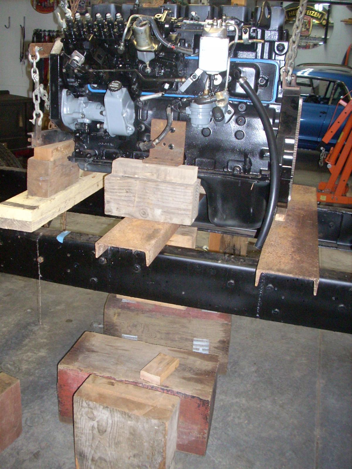
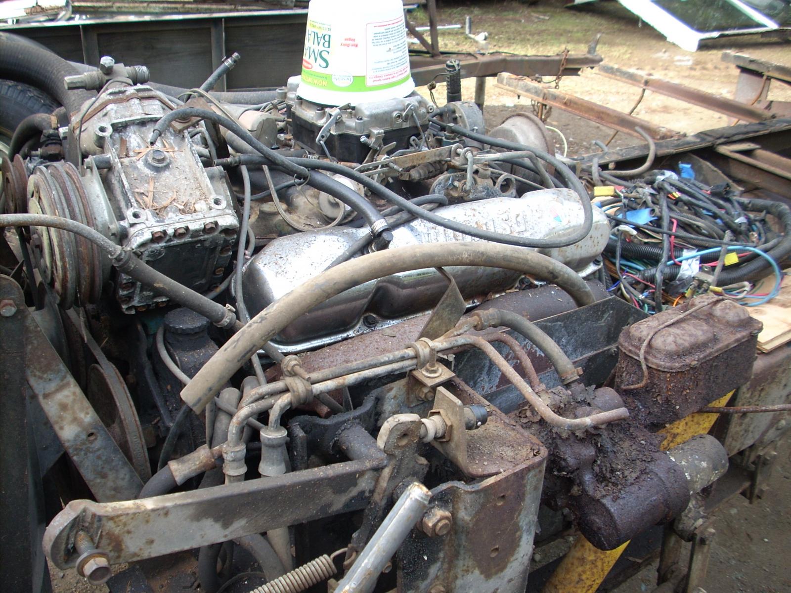
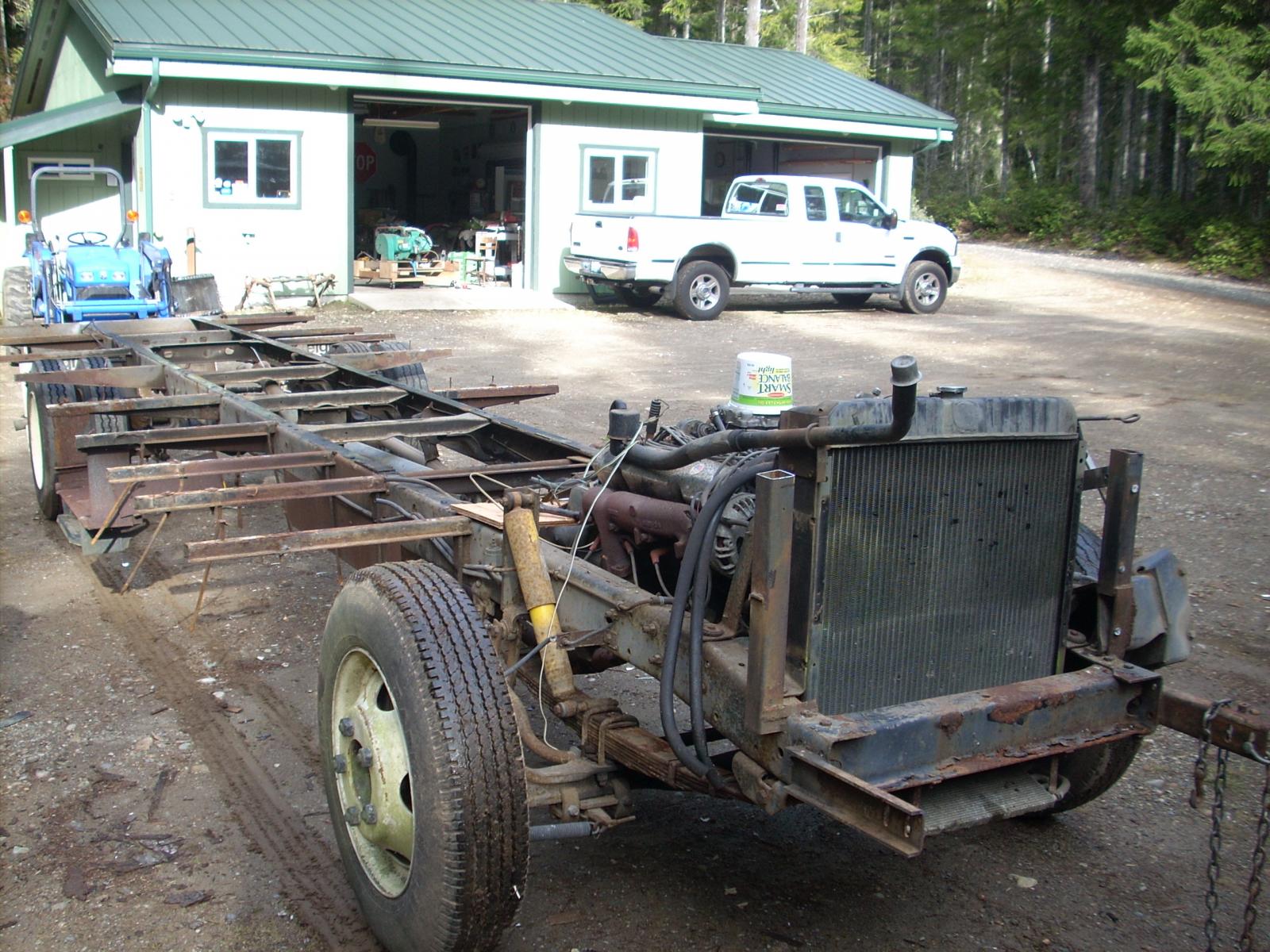
Bacon Creek, can't help you there; I'd contact American Wheel, I'm sure they could answer any questions. Thanks again for your interest in my "project". Part 7: As some of you probably noticed in Part 6 picture postings, the last photo shows a 96 5.9 Cummins engine between the rails. I obviously decided to take the leap and replace the 440 gasser; I found a 96 4WD unit through a friend of mine. The engine had been off the road since 2000, it was involved in a roll-over, pulled from the body and stored until I bought it (with the provision that I would pay for it after it was started). I'll attach a couple of pictures of it "chained" between the rails and some pre-start steps intended to ensure oil was cycled through the system before power was put to the starter. I made an oil cannister out of PVC, hooked up a pressure hose to the oil system and pressurized the cannister forcing the oil through the system, being observed in the rocker arms. The engine started after just a few cranks and ran like a top. I'll attach a few additional pictures showing "cleanup" and pre-installation. I know I'm still screwing up the way I post these offerings but don't know the right procedure. Thanks for your patience.

-
Looks great; you obviously have a knack or experience with metal mods. Keep it coming. A question, your posts have a definite separation between one post to the next; I have a project I'm posting on but they all run together. How do you get them "separated" where they can be responded to individually? Don't mean to take time from your project but could use "skill enhancement"; I'm obviously not good on the computer. Again, super, I love your posts.
-
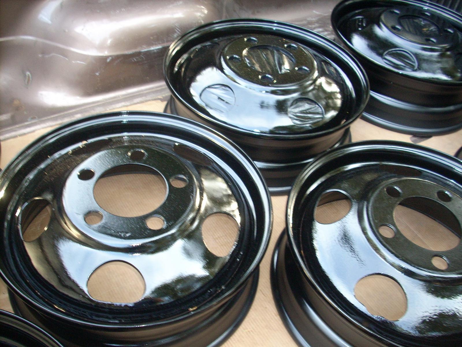
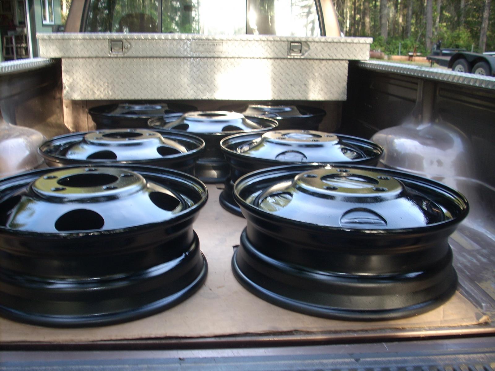
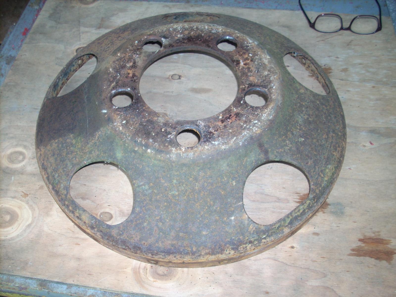
Bacon Creek: I agree, it has the potential to be loud and hot. I will install Dynomat (or equivalent). I plan on wrapping the exhaust from the turbo to the rear of the cab. If you have knowledge of other good materials that would help mitigate the noise/heat please let me know. Thanks for your interest Part 6: Wheels and tires. I previously alluded to the difficulty of finding 5 lug 20 inch tubeless wheels; they are out there on vehicles (usually Ford school buses) the owners of which don't want to sell. I did find two of them in a wrecking yard, I got so excited about the find that I bought them with tires mounted; when the tires were removed it became clear they were not a match, the rim widths were not the same. Ultimately I decided to move forward to obtain a "matched" 7 wheel set. Five lug "widow-makers" are plentiful and free to cheap. I obtained 7 of them and took them apart to obtain an unmolested hub. This required drilling out 18 rivets, then cutting "V" notches on the inside and outside lips and doing the same on the opposite side of the rim. Using a hand-held cutoff wheel I carefully cut a groove between the "V"s to weaken the metal between the two lips without cutting into the hub; then using a 10# sledge hammer to break the bond. This effort gave me 7 good hubs. I sent the hubs to "American Wheel Specialties" in Kennewick, WA to having new 22.5 inch tubeless rims mounted on the hubs. The did a great job, sandblasted the hubs, mounted the new rims and primered each unit. I picked them up in person to ensure that what 'WE' had fabricated was gong to work before taking possession of them - they were great. I had previously purchased a set (2 steering) and 5 (driver) 22.5 inch tires which I had mounted after painting (I didn't want to tie-up a lot of money in new tires to sit and age while I completed this fairly lengthy project).


-
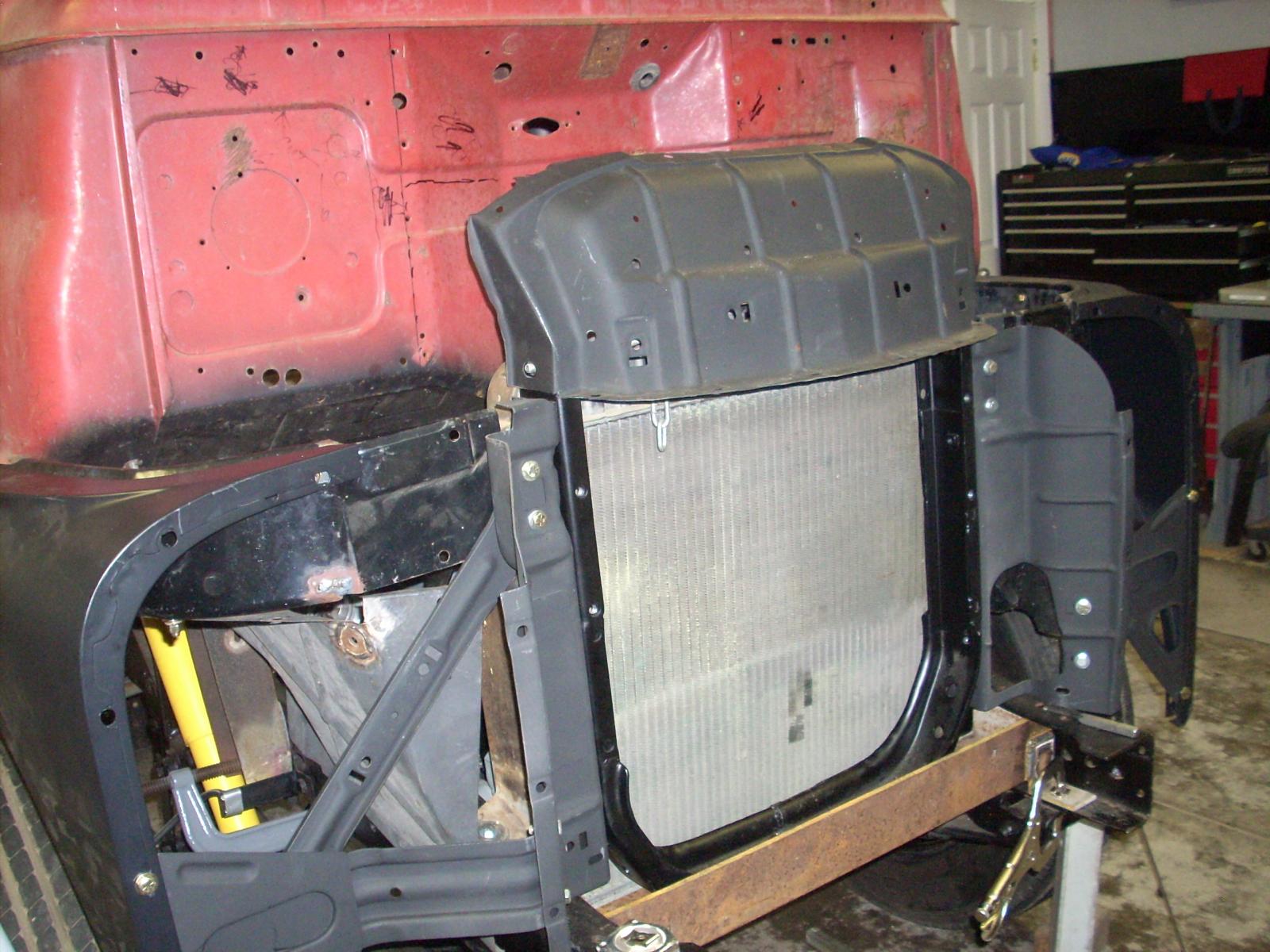
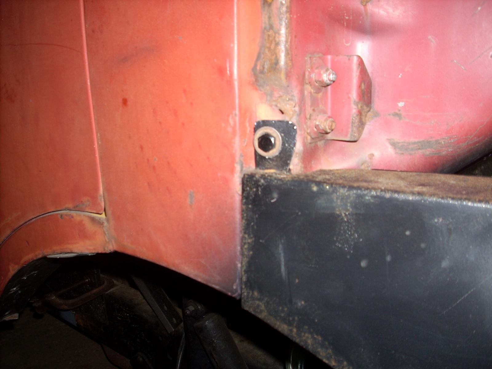
Part 5: Last session I alluded to difficulty in getting the cab to align with the core support and not be so high as to exaggerate the gap between the top edge of the front fender and the top of the tire (I still had the 19.5 tires on). In addition the cab was forced into a position that the wheel was not centered in the fender wheel opening. Taking these alignment problems one at a time I'll first address getting the wheel to center in the fender wheel opening. Some of you may be aware that the core support in this vintage Dodge truck had a "dogleg" in the vertical portion of the support; I'm going to attach a picture of the "dogleg" and the modification to correct the problem. The new core support took three different core supports to fabricate the final product which has a straight vertical orientation. Secondly, the stock 1977 MH cross member on which the core support was to be mounted on forced the core support to sit to high. I attempted to correct this by cutting a recess in the cross member and having a large angle iron piece welded in, still not enough. I then purchased a 3/8 3x4 inch thick angle iron and modified it to take the place of the stock unit. The combination of eliminating the "dogleg" and fabricating the "new" cross member solved the issue.

-
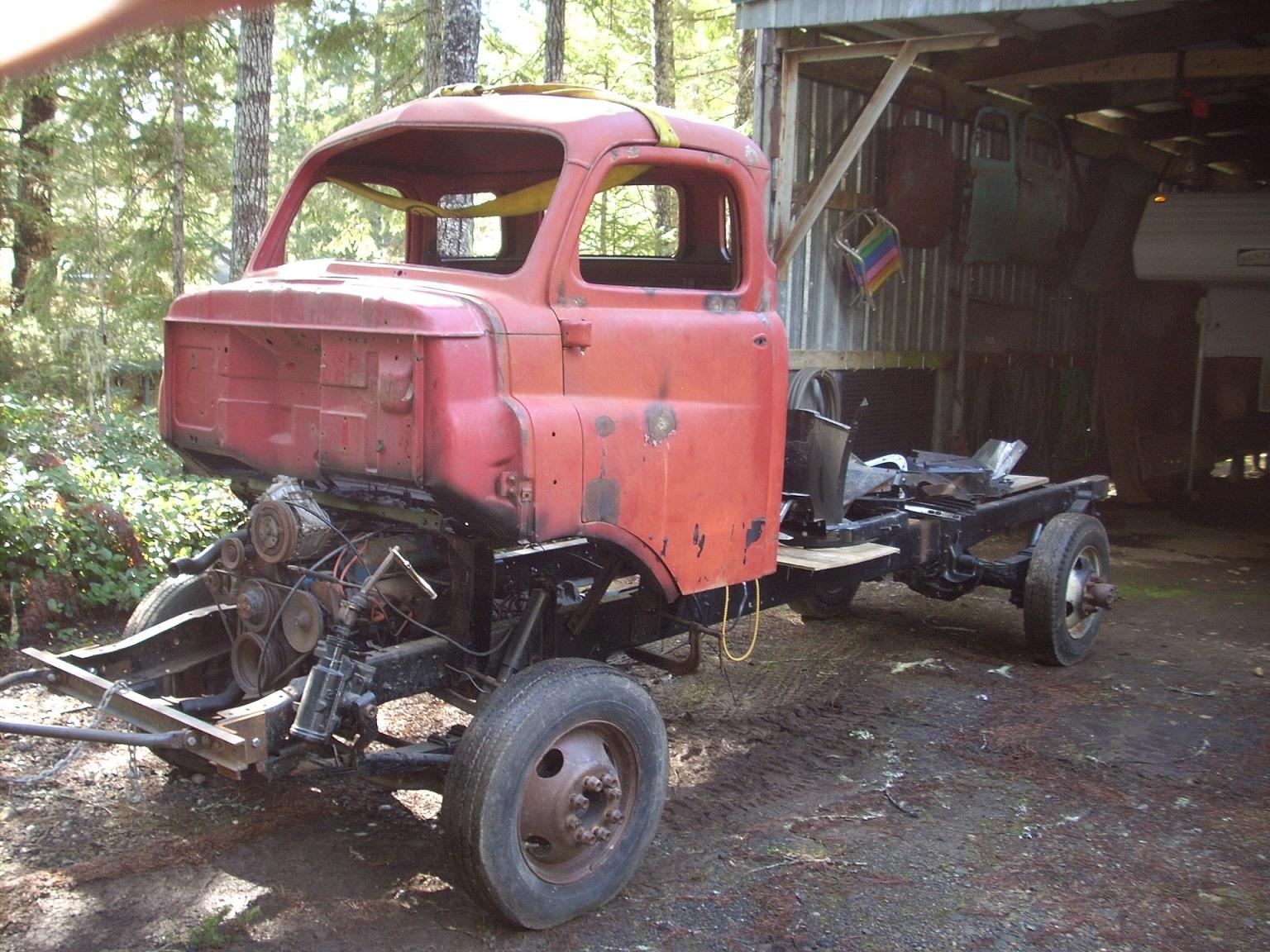
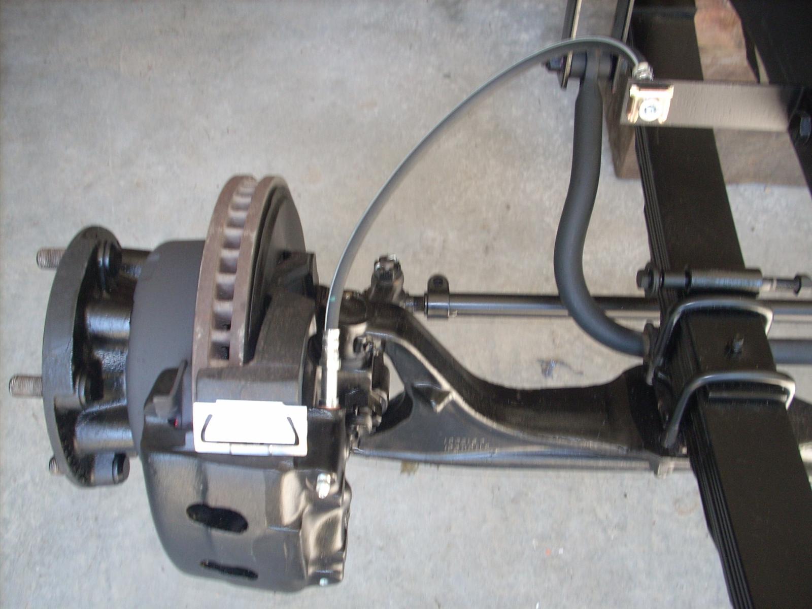
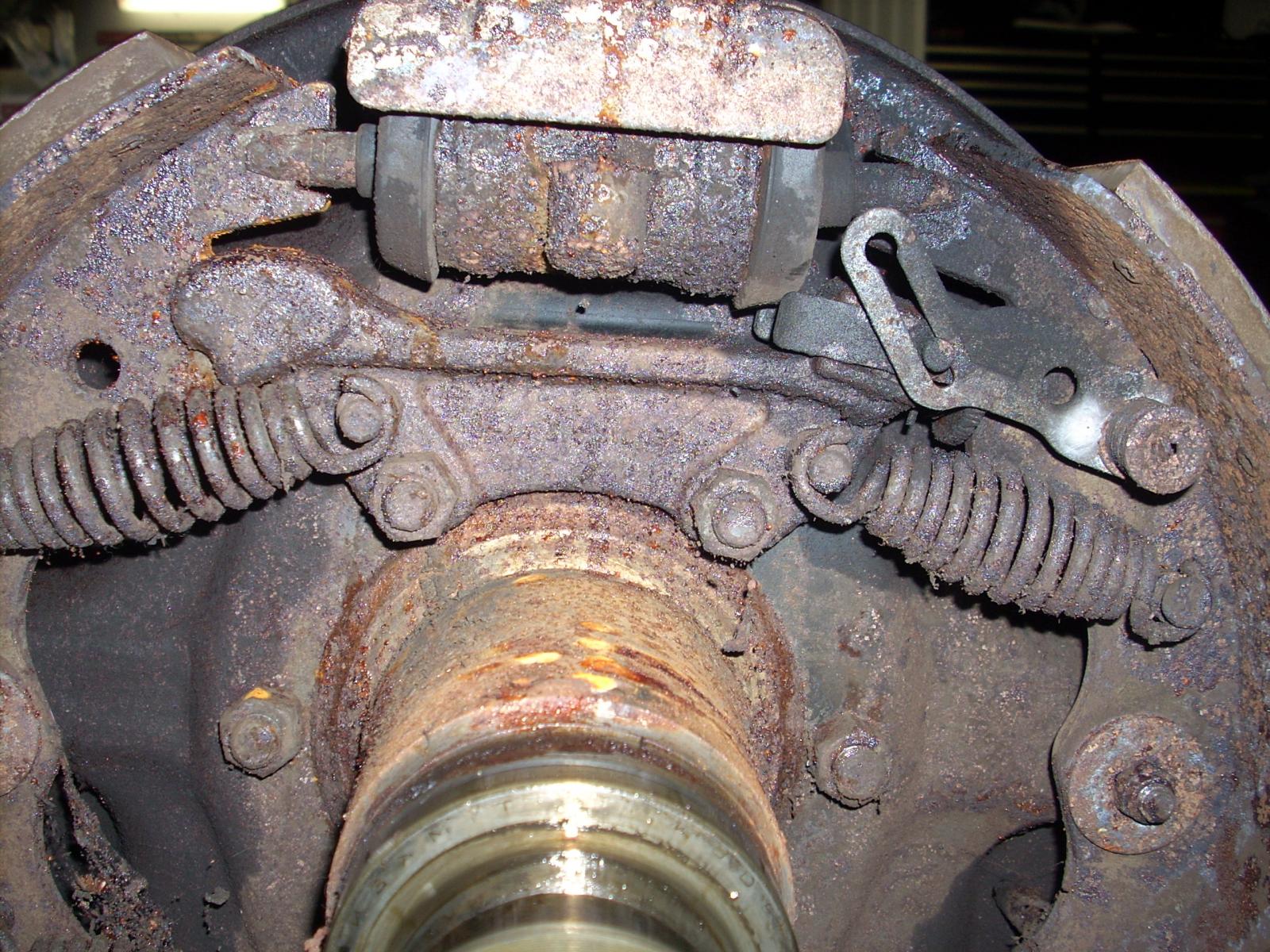
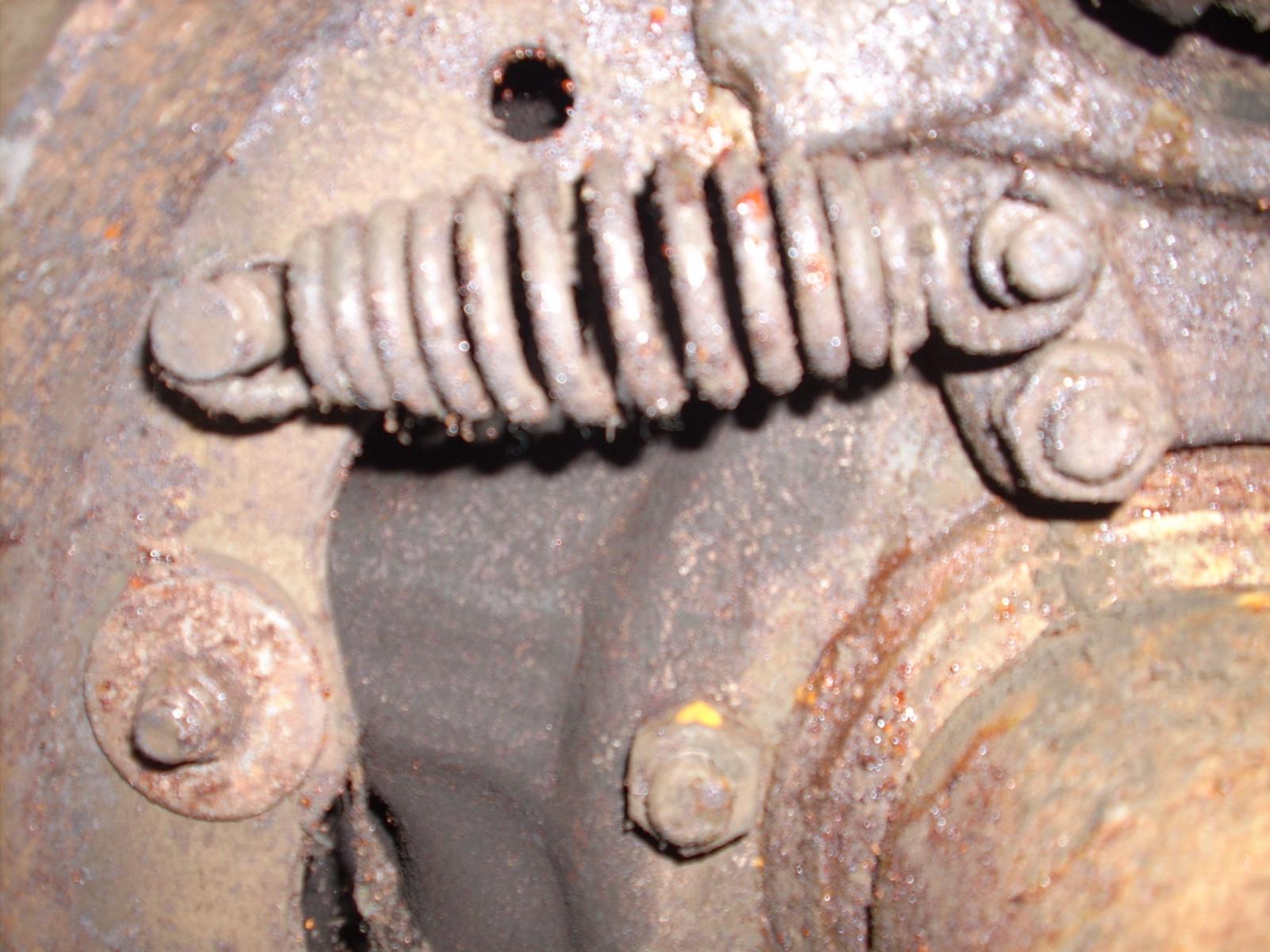
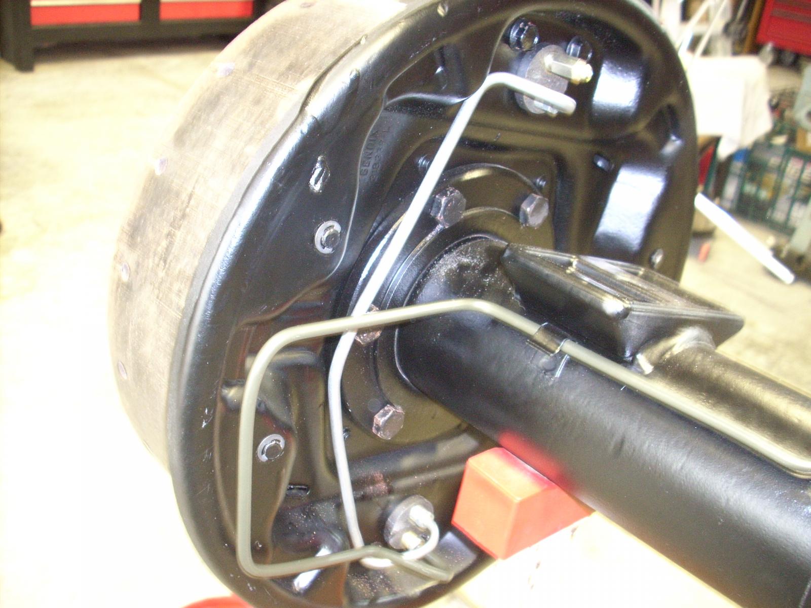
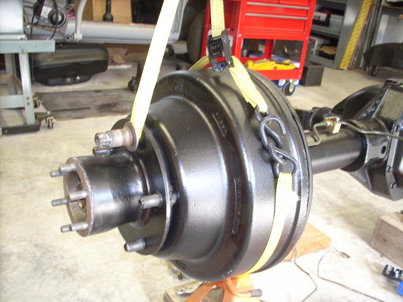
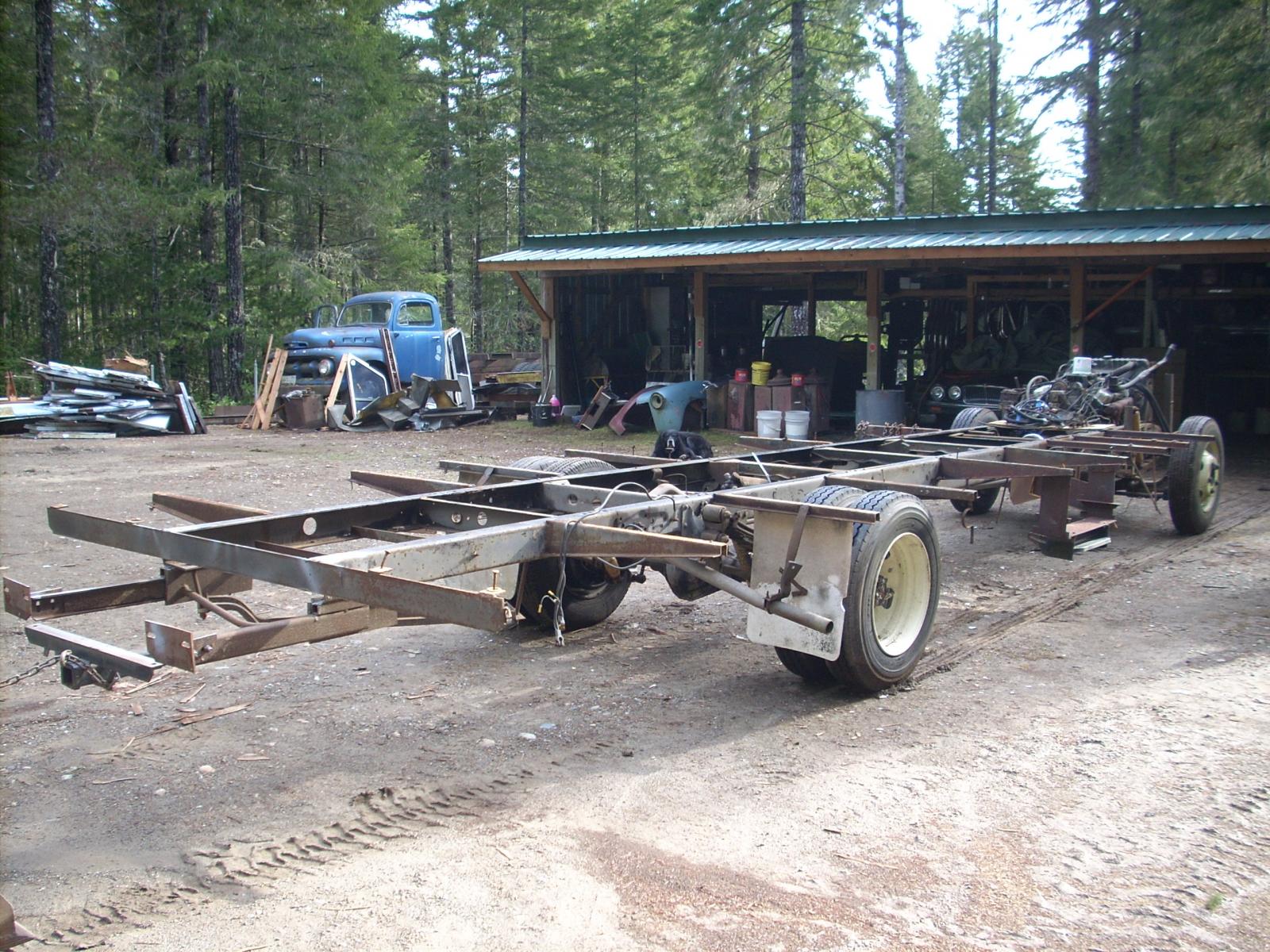
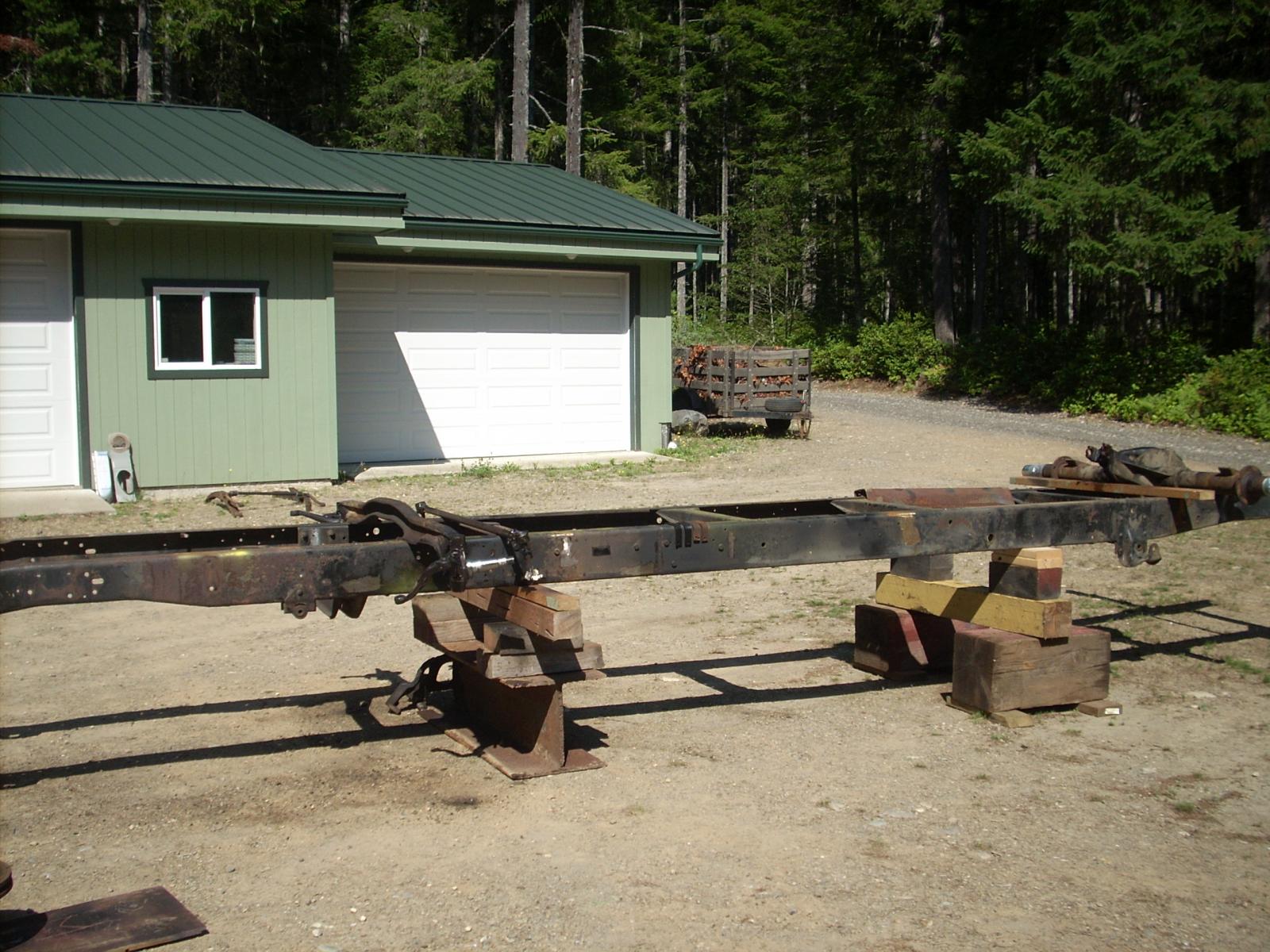
NIaacs and JAG1, thanks for your interest and comments. NIaacs, the front axel is an F50 rated at 5000 lbs, you're right, it is simply a heavier version of the M300 axel. The differential is a Spicer 70HD with a load rating of 10,000 lbs with 4.56 gear ratio; that was another reason for my effort to get the 22.5 inch rims. The M600 chassis had Rockwell axels with six lugs and significantly greater weight capacities. I found a set in AZ, I thought the shipping costs were prohibitive - wish I had done it, those wheels are easy to find and you can get them in aluminum. Thanks again for your interest. Jag1, thank you. It seems you are the man behind the site; I am not very proficient on these sites. I would like to delete my long ago attempt at sharing this which shows up on each of my current posts, can you tell me how to do that? Thanks again. Part 4: Once I was able to get the newly painted frame in my shop I blocked it up in order to install the frong and rear axels and get the chassis back on its wheels. Once that was accomplished I began the rebuilding of the rear brake drums and had the front rotors turned and rebuilt calipers to install.. I took advantage of the easy access to ifabricate and install new brake lines on the rear axel. On the subject of brakes, the hydro-boost system that was on the MH was huge and in need of a major overhaul; I determined that I would not use it on the project Once I got the chassis on it's wheels I went about mounting the cab. At that time I was still going down the path of rebuilding one of my 440'/727 units as my power source and I wanted to ensure clearance and where the cab would fit relative to the front wheel openings. I'll attach some pictures of these efforts. As you will probably notice is that the cab was to far forward and to high; as I imagine anyone reading this knows, the cab needs to be in proper relationship to the core support; pictures will show that I was way off and had to make some significant changes to the support structure.
-
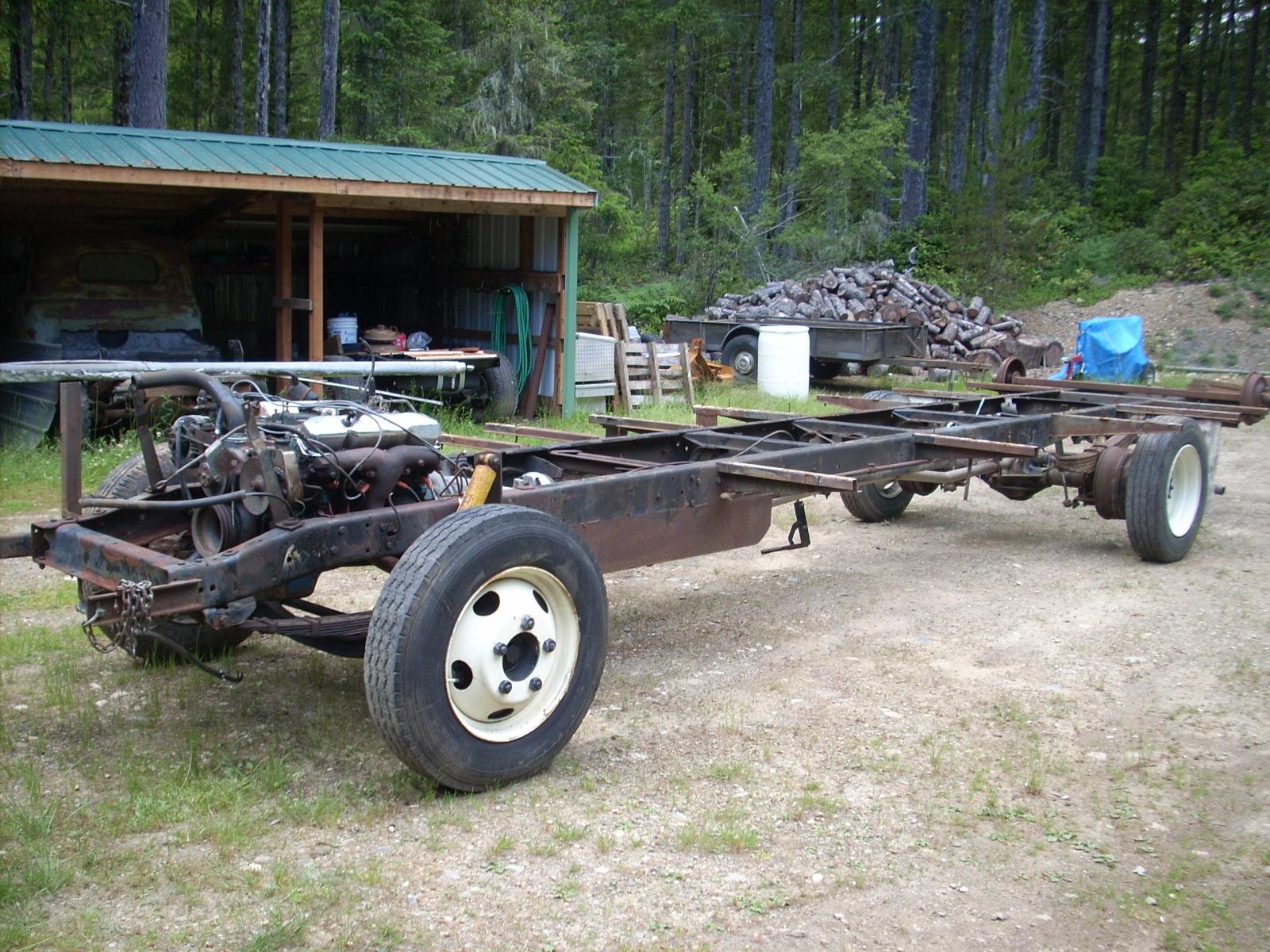
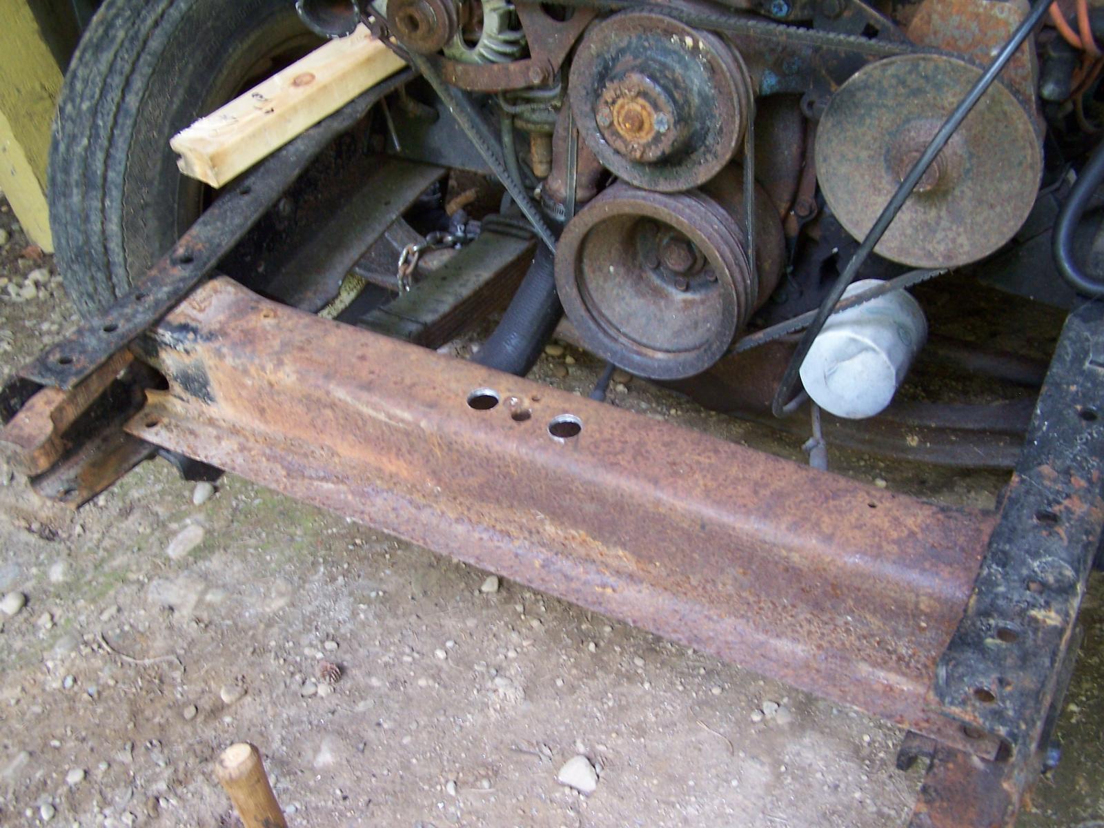
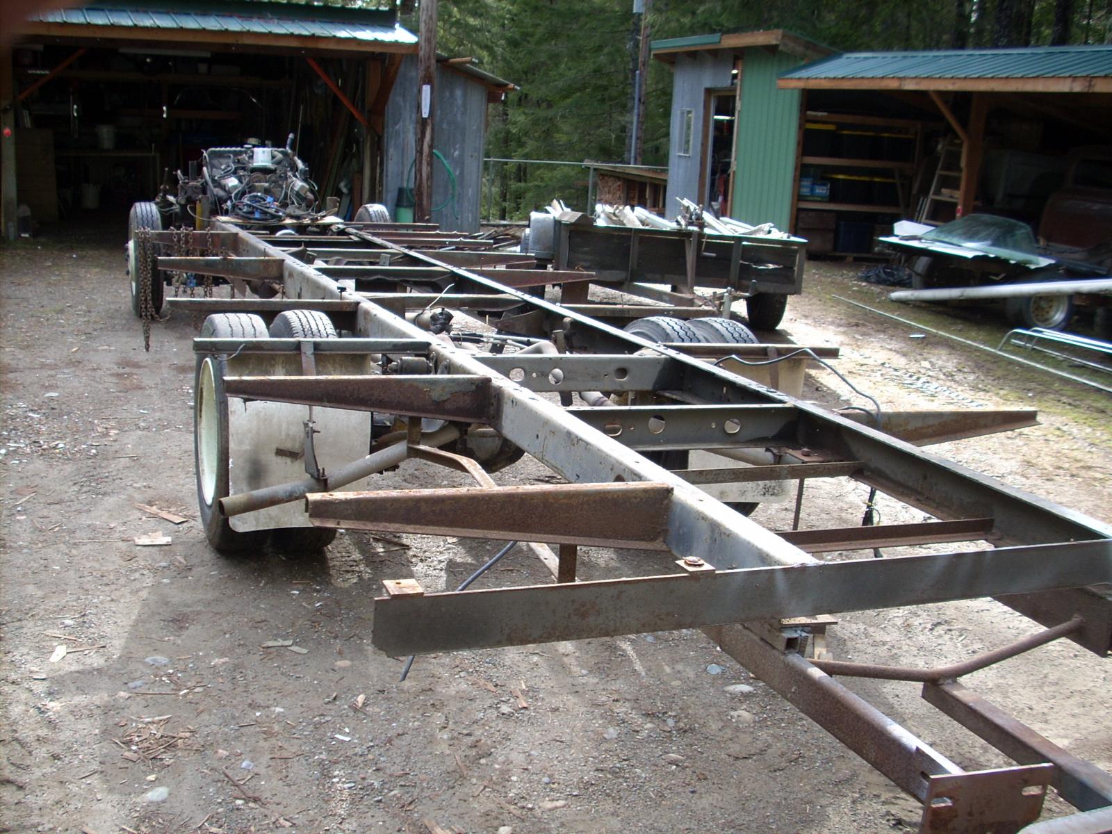
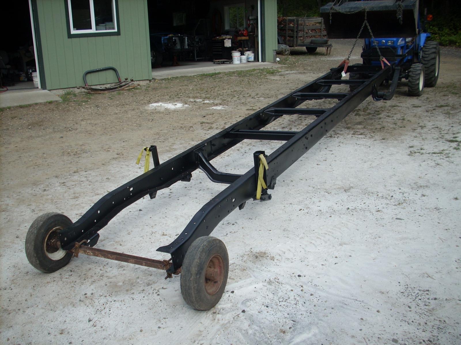
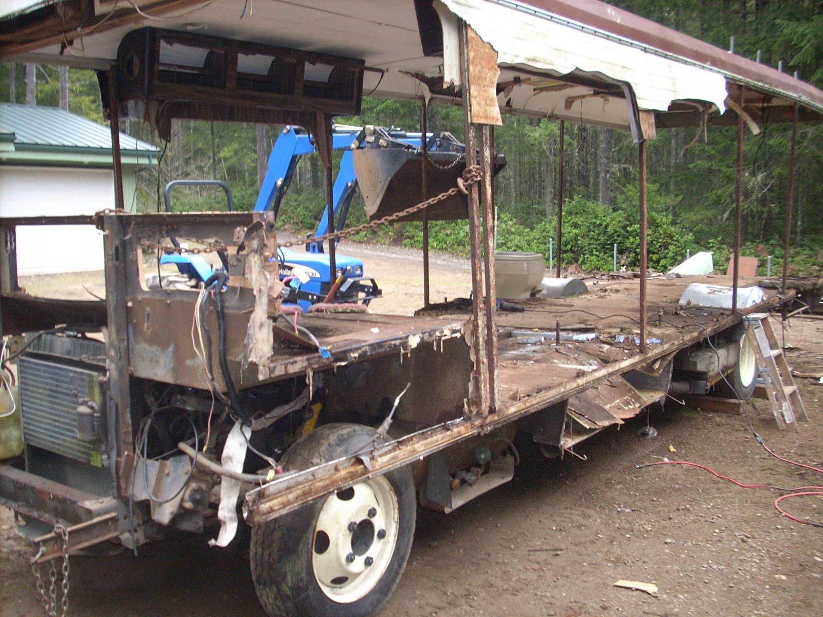
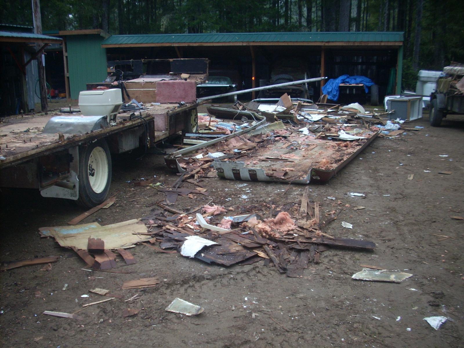
Part 3: The pictures below reflect the bare chassis that still has the "outriggers' that supported the extended floors and the long overhang behind the rear axel. I borrowed the neighbors plasma cutter to make easy work of their removal, also removed about 4ft of the rear overhang (I'm not going to need it because I'm going to be installing a tilt flatbed when I get to that point 9there is enough "tail" there to accommodate placement of the trunions when I get to that stage. You might notice the sandblast residue from my blasting the frame (both front and rear axels were removed prior to blasting and were "delicately" done separately. I thank my lucky stars for my tractor, I'm not a young guy and I'm not the hunk I used to be.


-
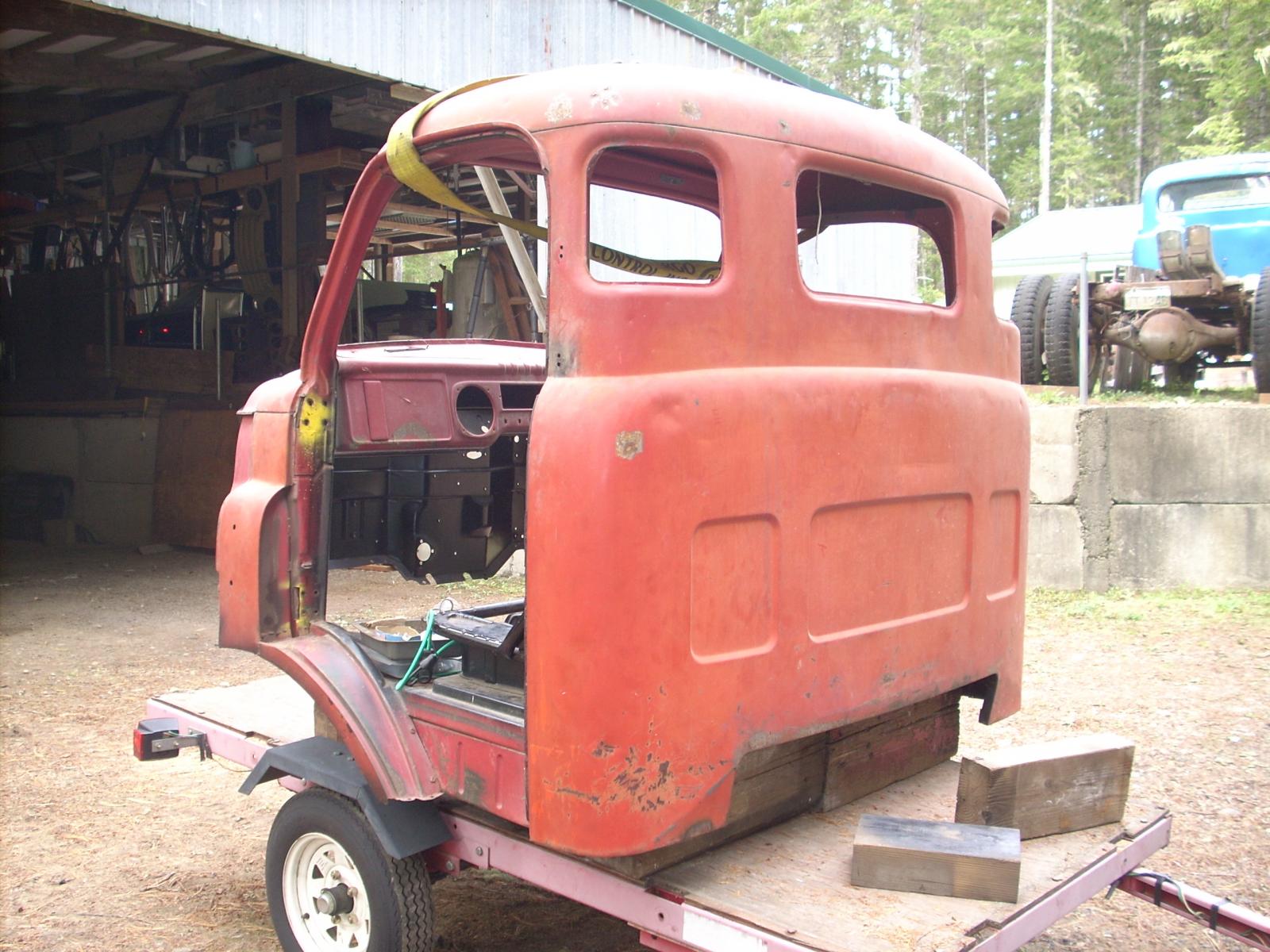
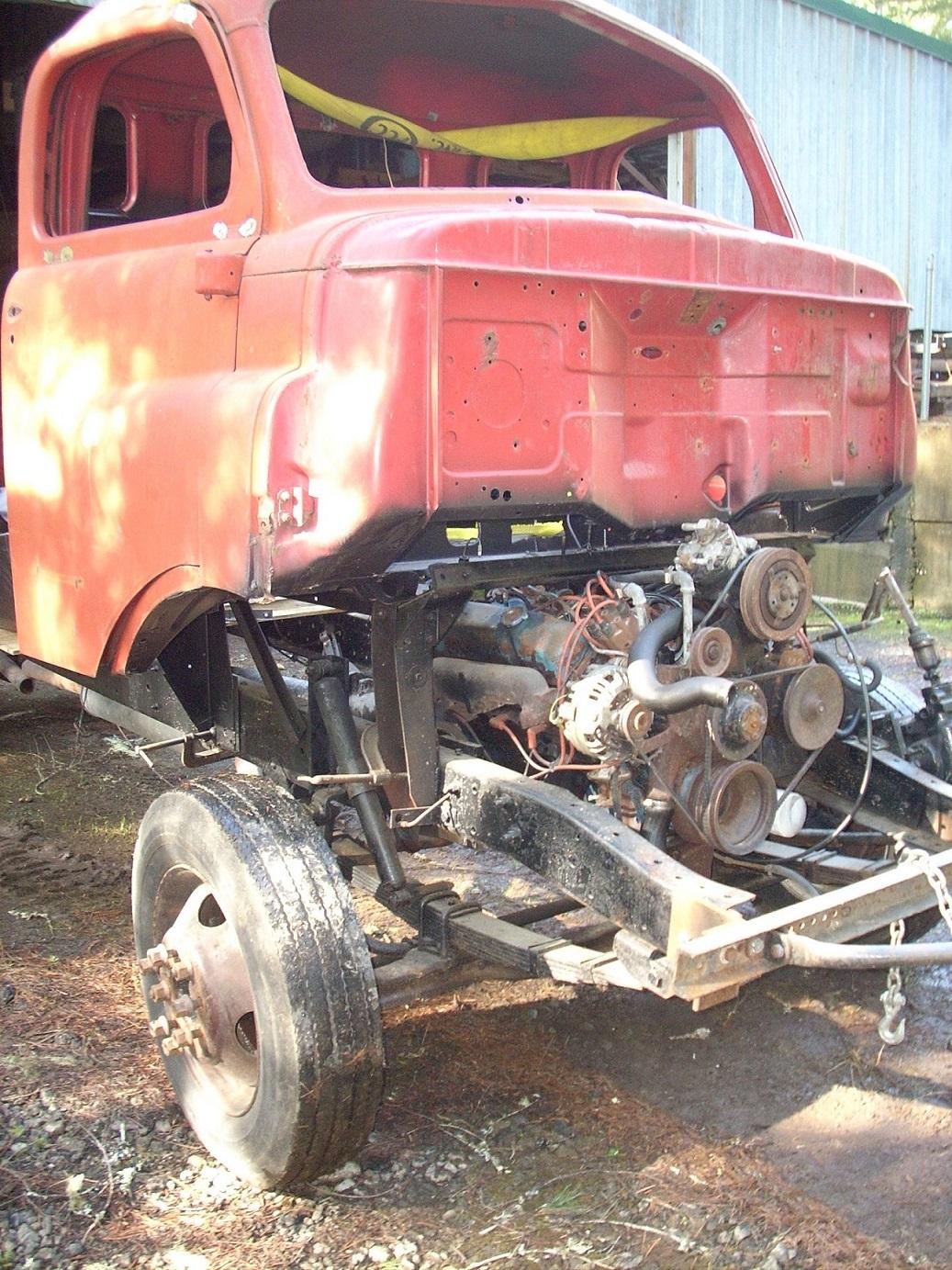
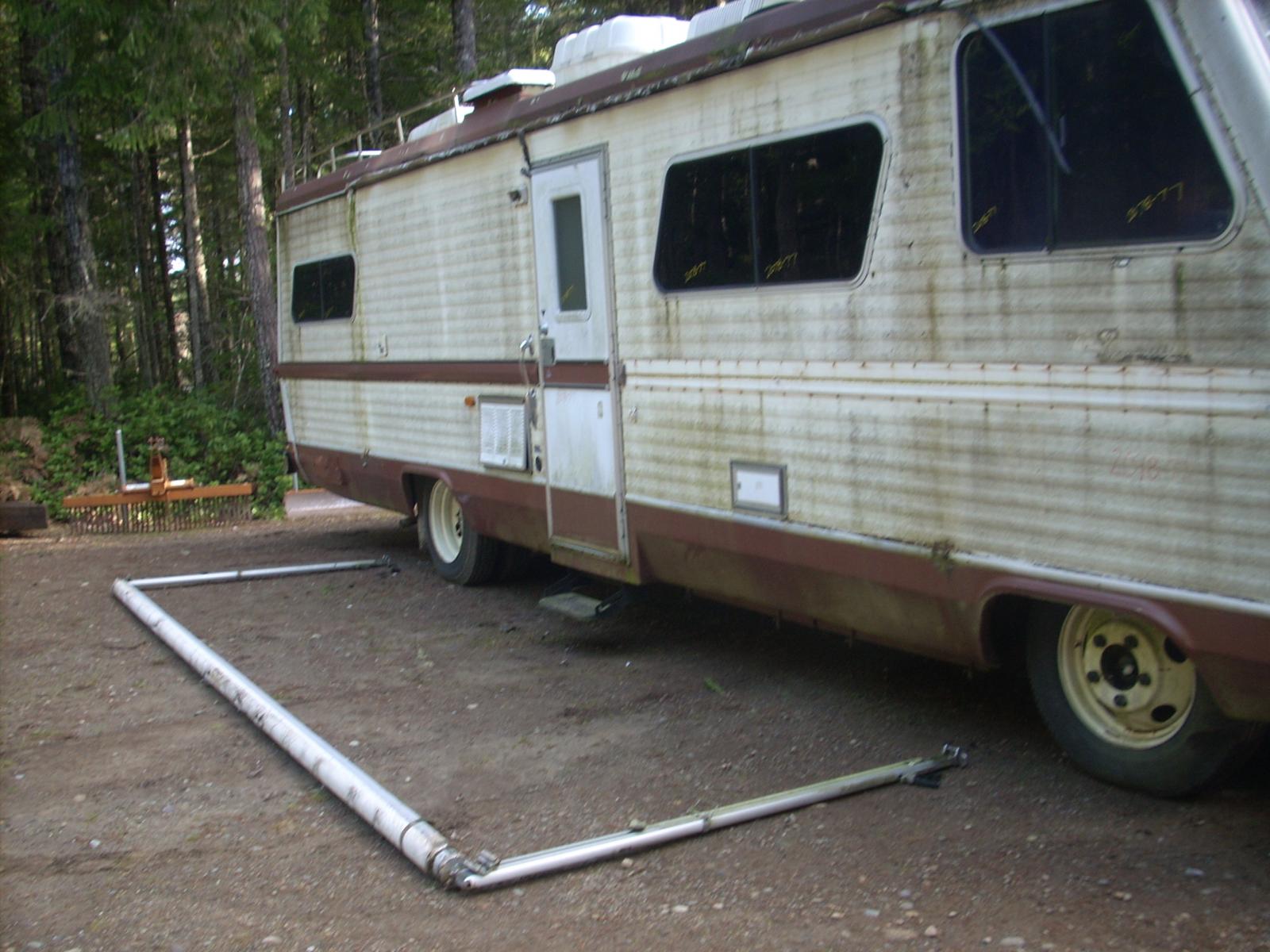
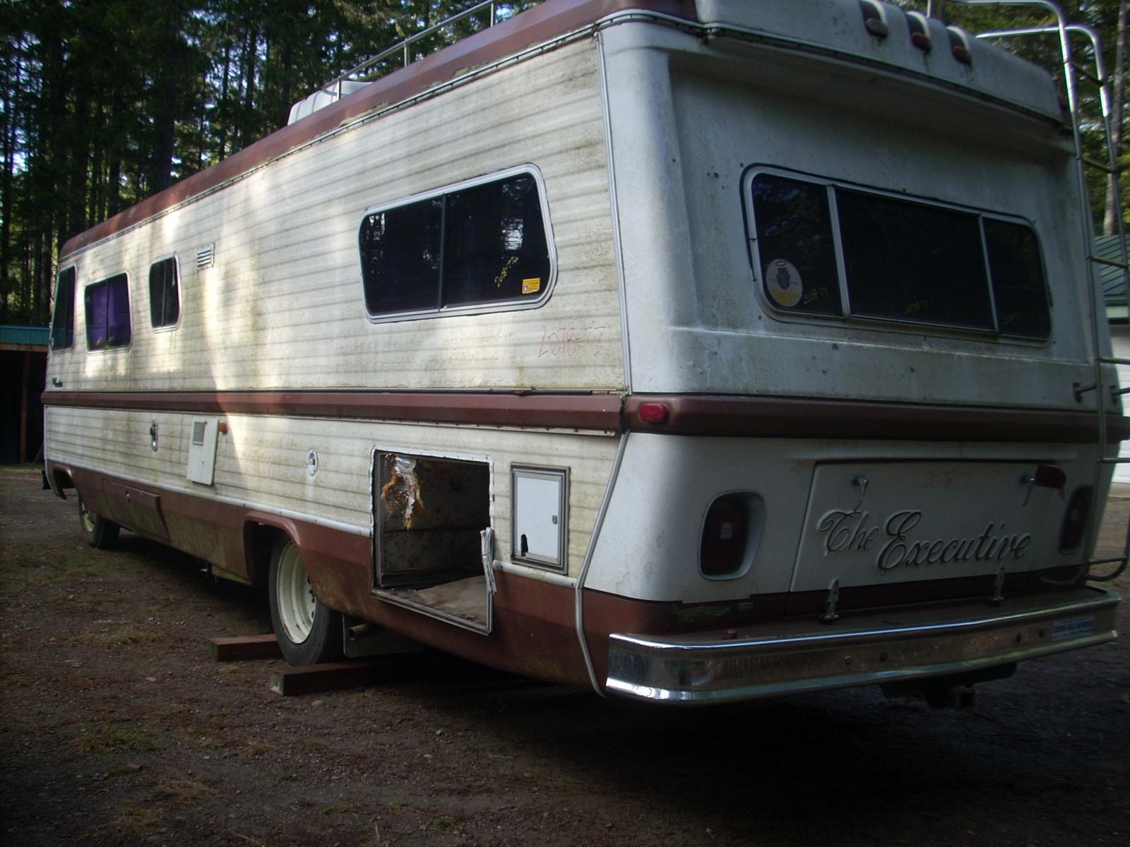
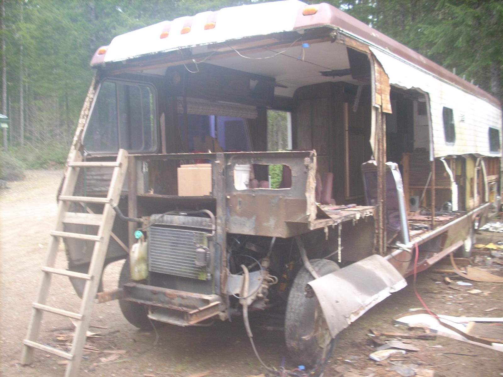
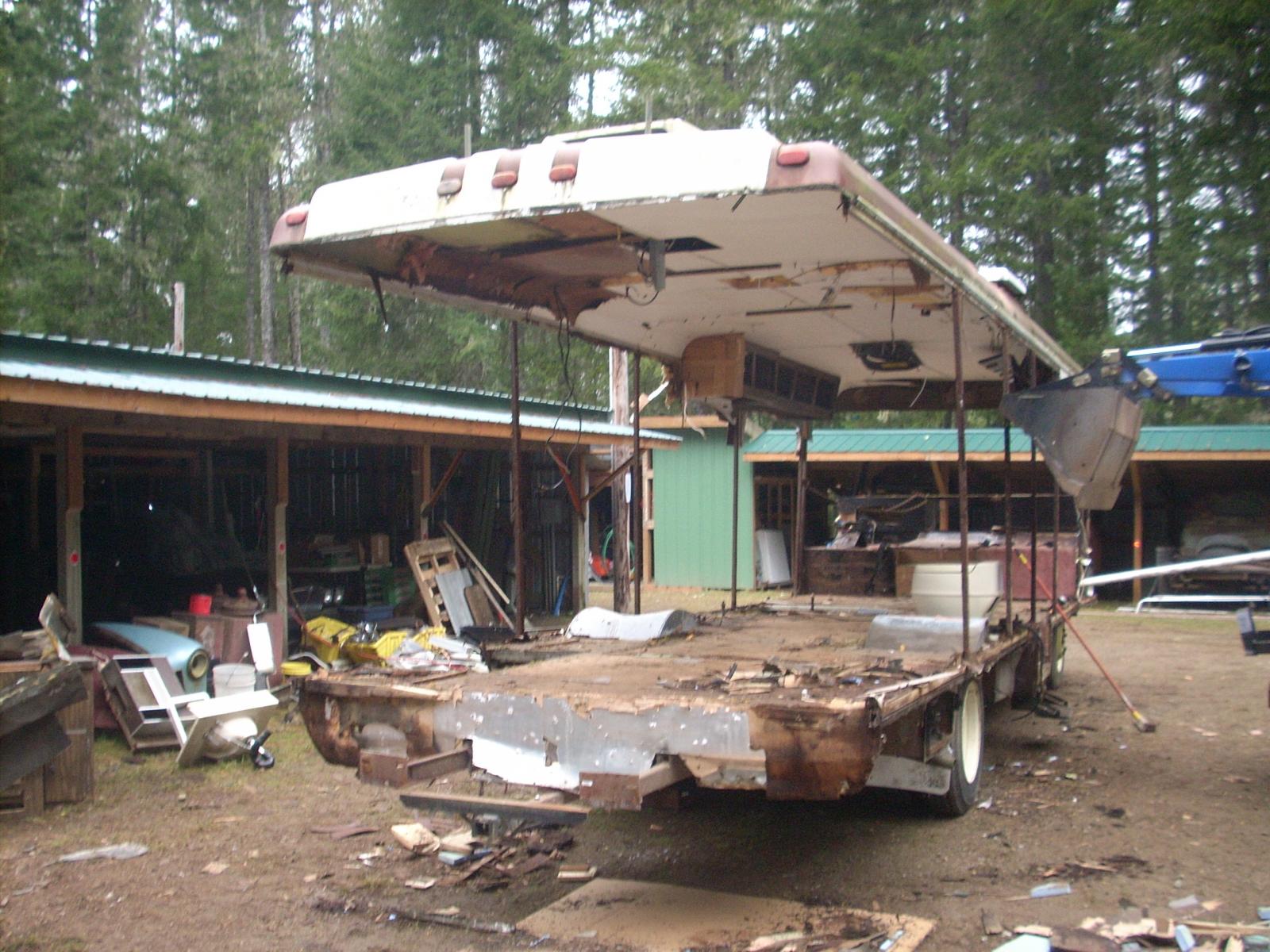
These pictures reflect My "project" as I bought it. As you can see it has a 440/727 engine/transmission combination. In addition it is on a 1978 Dodge M300 MH chassis with 17.5 inch wheels. My intent on buying this was to restore it as a "truck", I'm not into the "slamming school", though I respect the right of others to pursue their vision; there are just too few of these particular trucks to deny them there place in history. Having said that, I always do what I call a performance upgrade to most of my projects; in this case I have opted to replace the 440/727 with a 1996 5.9BT low miles diesel and a 47re transmission. Following submissions will include the "teardown" of what became my chassis, then the "fitment" challenges (of which there were/are many). I do need some help in one area (that I know of), I badly need a 2WD wiring harness, my intent is to use a 96-98 wiring harness which accommodates the 47RE 2WD transmission. More to follow. Part 2: As I mentioned previously I wanted to build a truck, the smaller M300 Dodge MH chassis was too small for my objective. I had seen a 32 foot Executive MH in a local wrecking yard that was built on a 1977 Dodge M500 MH chassis with 19.5 inch wheels which I picked up for $800.00 delivered (so now I have two 440/727 units), also got a low hours Onan 6.5 kw generator which runs great. These pictures reflect a couple of the steps in demolition, my only concern was not to do damage to the chassis/suspension. I say to those of you who motorhome; I hope yours is better built than this one was.


-
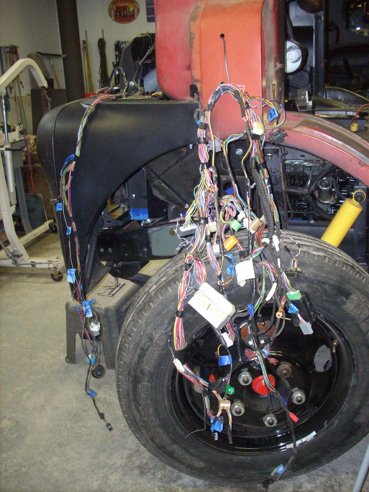
The project I'm working on that might be of interest to this forum is the 1948 Dodge COE with 1996 Cummins 5.9 I've got the structural and body fit problems resolved; current focus is on the harness; I've got a 1998 (12V) complete wiring harness, it appears that the engine harness is a pretty easy adaptation; now considering the harness came out of a traditional Ram 2500 I've had to make provision for re-routing some branches of the harness to provide for the much different layout required for the COE. My intent was to "strip" un-needed wires from the body/interior systems; specifically ABS, Airbag System, Seatbelt electrical components and Instrument components. I intend to use SW gauges which means buying or fabrication of a traditional 12V harness. All sounds easy, I found the removal of the ABS could be done by wire removal up to the Power Distribution System don't really know if I have created problems by this approach since I cannot test the system until more is "hooked up or modified. I'm finding the other sections I want to remove are inner-connected to systems I don't want to remove such as Cruise Control (I'm trying to use the 98 Steering column), Door Locks, etc. Any knowledgable help appreciated. Jim 360-372-2874