Alrighty gang, I finally got my new switch installed last weekend. I figured I would go through some of the basics on how I did my install just so others can have an idea on how to do theirs.
When you get your switch in the mail, it should have the following things included:
-The actual switch with wiring and connectors
-A small piece of 3/8's heavy walled plastic tubing
-Three 1" screws
If something is missing, DAP will take care of your needs. If not, I am sure Ed could lend a helping hand wherever needed.
First thing I did was remove the dash bezel. It just has pop clips all over the place that hold it to the front of the dash and around the cluster, radio, HVAC controls, etc. BE CAREFUL pulling this baby off because for the most part, they are old and brittle. Mine cracked in a few different places the last couple times of pulling it off.
Next, there are three screws holding the little cubby in place to the right of the radio. Remove them and pull the cubby out of the dash. Do whatever you want with it and the screws that were holding it in as they arent long enough to reuse when installing the switch.
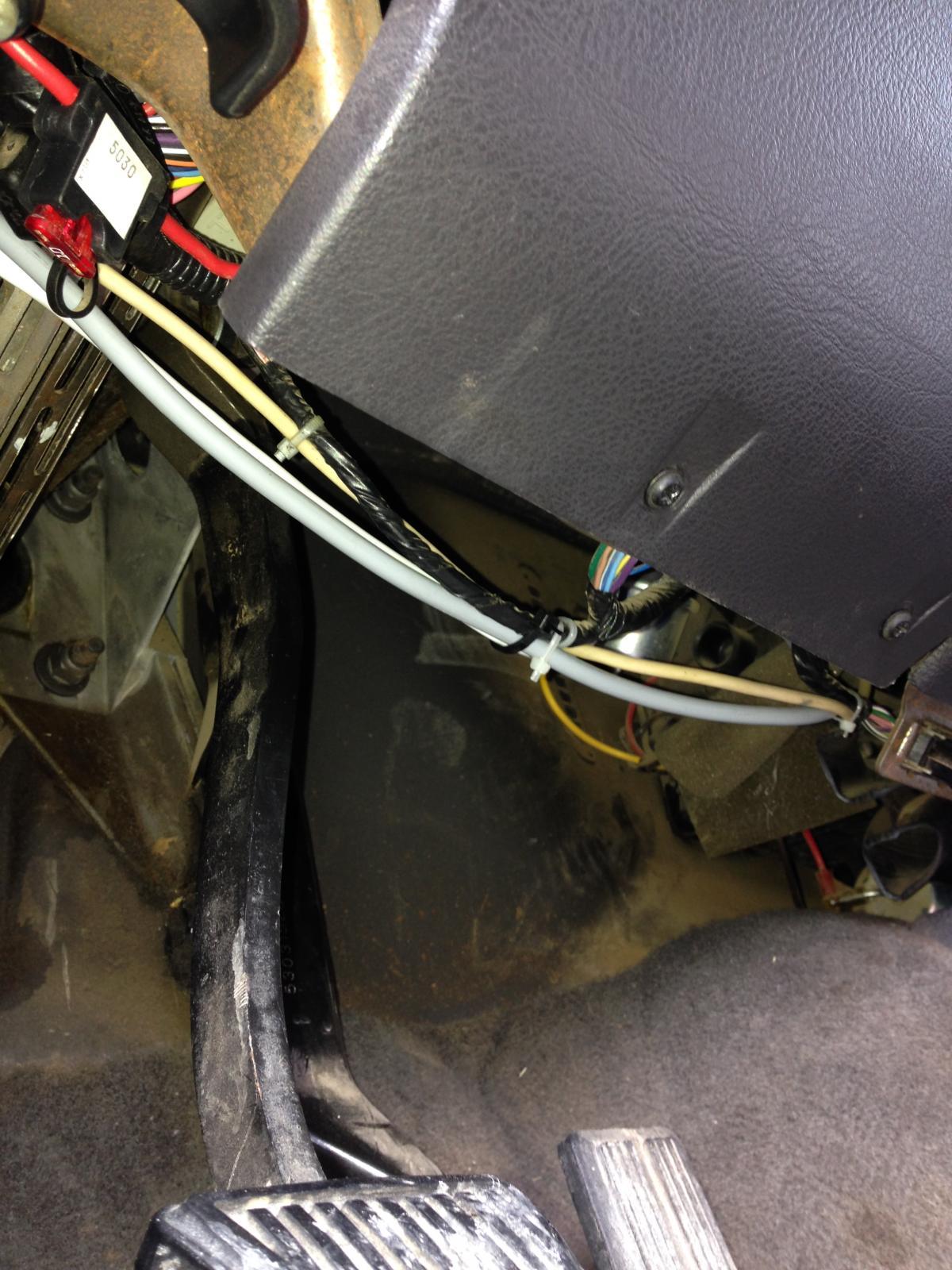
Now you can start feeding the cables though the dash. I just went toward the left a little ways and then down to the bottom edge of the knee bolster. I have some other accessory wiring running along that bottom edge so I just followed that as you can see in the pictures. As long as you stay right at the bottom edge of the bolster, you can keep going until you are right before the E-Brake pedal.
Once you get the wiring fed through the dash for the most part, you can go ahead and actually mount the switch in the dash. Take that little piece of plastic tubing and using a razor knife, cut three 1/2" long pieces. Those are going to be spacers that the switch face will sit on. Without them the switch face would not fit flush out to the bezel. Use the longer screws and the same holes that the cubby was mounted with. This is the order that the screws will go through.
Screw -> switch face -> plastic spacer -> dash
Now head toward the firewall with the wiring. This is the tricky part as there is only one hole in the firewall to go through.
If you are like me, You have a ton of other stuff running through that hole already. Not much room. You cant really reach that hole from the inside of the truck because of all the stuff they have mounted in the area, especially if you have a clutch pedal there too. I actually went out under the hood and fed a straightened metal hanger through to the inside of the cab. Then I just made a loop and the end and used it to pull the cable and connectors through the hole. Make sure you only pull through one connector at a time!!! If you try to do all four, you are likely to pull the wires out of them or even break the wiring.
PULL LIGHTLY to get the connectors to slip through.
The rest of the wiring is pretty straight forward. The shorter part of the connector harness will go to the Intake Air Temp sensor toward the back of the head on the engine. The longer connector will go to the Coolant Temp sensor on the front of the head.
After you get everything plugged in, now you can go back through and tie everything up however you like it. I tried to follow as much existing harness as I could throughout the whole install just so I would have something to tie up to.
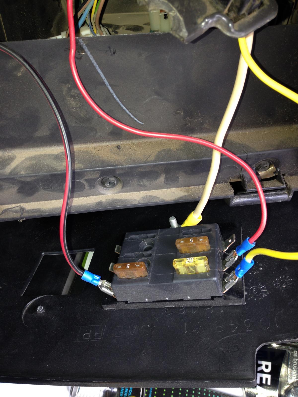
As for wiring up the LED light on the switch, that is the other wire coming from the switch that doesnt have any connectors already on it. You will notice that there are a red and a black wire inside the protective covering. You can either run it over to the fuse panel on the driver's side of the dash or another source of power. I would suggest you tap into somewhere that has constant power all the time. This way even if the truck is off, you will still know that the switch is on. Because I have some other gadgets in the cab, I have installed an auxillary fuse panel in the back of the glove box and thats where I tapped into power for the light. The black wire just needs to be grounded to the truck somewhere.
I have attached a few pictures but I can take more if anyone wants a better view or more information on the install.
I also wanted to say thank you to Ed and Mike and DAP for making these switches possible for us. It is a great investment and I think anyone with a 24v Cummins Turbo Diesel should have one.


Alrighty gang, I finally got my new switch installed last weekend. I figured I would go through some of the basics on how I did my install just so others can have an idea on how to do theirs.
When you get your switch in the mail, it should have the following things included:
-The actual switch with wiring and connectors
-A small piece of 3/8's heavy walled plastic tubing
-Three 1" screws
If something is missing, DAP will take care of your needs. If not, I am sure Ed could lend a helping hand wherever needed.
First thing I did was remove the dash bezel. It just has pop clips all over the place that hold it to the front of the dash and around the cluster, radio, HVAC controls, etc. BE CAREFUL pulling this baby off because for the most part, they are old and brittle. Mine cracked in a few different places the last couple times of pulling it off.
Next, there are three screws holding the little cubby in place to the right of the radio. Remove them and pull the cubby out of the dash. Do whatever you want with it and the screws that were holding it in as they arent long enough to reuse when installing the switch.
Now you can start feeding the cables though the dash. I just went toward the left a little ways and then down to the bottom edge of the knee bolster. I have some other accessory wiring running along that bottom edge so I just followed that as you can see in the pictures. As long as you stay right at the bottom edge of the bolster, you can keep going until you are right before the E-Brake pedal.
Once you get the wiring fed through the dash for the most part, you can go ahead and actually mount the switch in the dash. Take that little piece of plastic tubing and using a razor knife, cut three 1/2" long pieces. Those are going to be spacers that the switch face will sit on. Without them the switch face would not fit flush out to the bezel. Use the longer screws and the same holes that the cubby was mounted with. This is the order that the screws will go through.
Screw -> switch face -> plastic spacer -> dash
Now head toward the firewall with the wiring. This is the tricky part as there is only one hole in the firewall to go through.
If you are like me, You have a ton of other stuff running through that hole already. Not much room. You cant really reach that hole from the inside of the truck because of all the stuff they have mounted in the area, especially if you have a clutch pedal there too. I actually went out under the hood and fed a straightened metal hanger through to the inside of the cab. Then I just made a loop and the end and used it to pull the cable and connectors through the hole. Make sure you only pull through one connector at a time!!! If you try to do all four, you are likely to pull the wires out of them or even break the wiring.
PULL LIGHTLY to get the connectors to slip through.
The rest of the wiring is pretty straight forward. The shorter part of the connector harness will go to the Intake Air Temp sensor toward the back of the head on the engine. The longer connector will go to the Coolant Temp sensor on the front of the head.
After you get everything plugged in, now you can go back through and tie everything up however you like it. I tried to follow as much existing harness as I could throughout the whole install just so I would have something to tie up to.
As for wiring up the LED light on the switch, that is the other wire coming from the switch that doesnt have any connectors already on it. You will notice that there are a red and a black wire inside the protective covering. You can either run it over to the fuse panel on the driver's side of the dash or another source of power. I would suggest you tap into somewhere that has constant power all the time. This way even if the truck is off, you will still know that the switch is on. Because I have some other gadgets in the cab, I have installed an auxillary fuse panel in the back of the glove box and thats where I tapped into power for the light. The black wire just needs to be grounded to the truck somewhere.
I have attached a few pictures but I can take more if anyone wants a better view or more information on the install.
I also wanted to say thank you to Ed and Mike and DAP for making these switches possible for us. It is a great investment and I think anyone with a 24v Cummins Turbo Diesel should have one.