So, I have been running my compound setup for 3 weeks now, and I am impressed on all levels. For 1500$, I have instant boost, 24 MPG, and even when I fuel it like a dragster, The highest EGT I can get is 1280*.
Because of my awesome experience, I have decided to share the entire installation and give a few tips for anyone who wants to go this way.
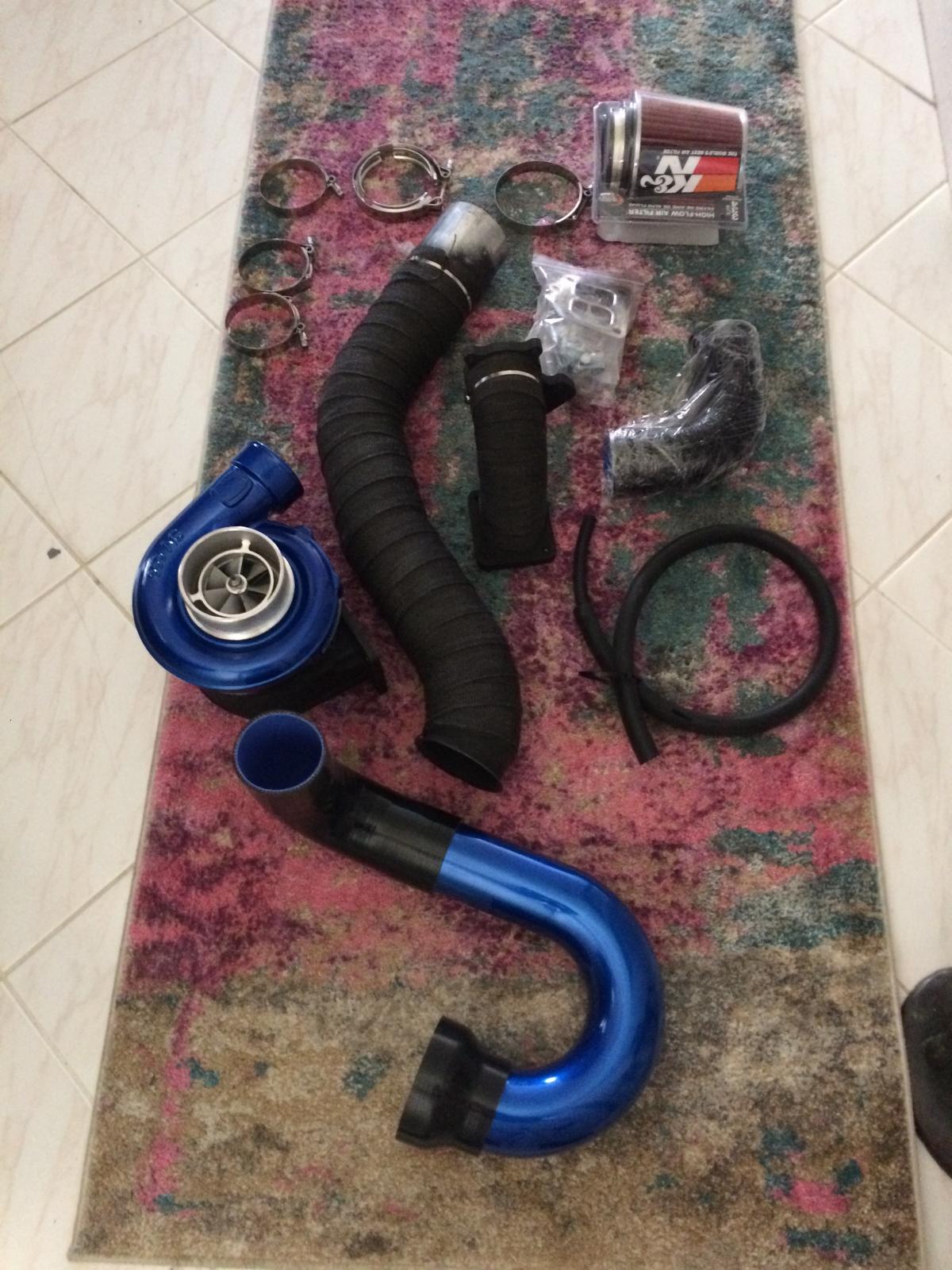
The kit I purchased is the Evilfab525 kit, here is the website link : http://www.evilfabperformance.com/shop


To start this project I inventoried all of the pieces in the kit, verified the S366 T4 turbo was clean and operational, and then set out on disassembly.
Problems encountered here - The factory downpipe / 5 bolt manifold had a bolt already broken off, and another one broke on me as well. Repair involved a drill press, tap and die kit, lots of lubricant, and patience.
.JPG.8c6bde8ea10efc6479003c96e740c19d.JPG)
.JPG.013e685770af09a0a995d17150ae7f25.JPG)

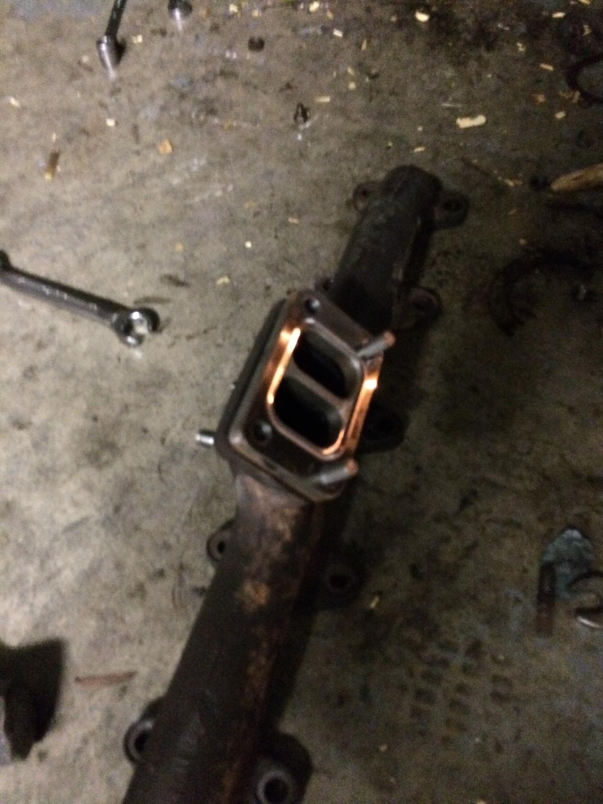
So moving on, the T3 HX35 uses 4 studs, two on manifold and two on turbine housing. Trash them!
This kit requires inverting the exhaust manifold, so the HX35 will be 180* and will require restudding / drilling out threads as required. The instructions provided very good info on this, and the fabricator Riley can answer any questions quickly before you get into trouble.
Also you will need to knock out the rear oil drain freeze plug, and chopsaw your HX35 drain pipe for the S366 Drain. Read the instructions on this part carefully!
After you have your length of drain tube, here's a tip: you should have 2.5- 3.5 inches of straight pipe. take electrical tape and tape the end you intend to tap into the block, marking a depth of 1 - 1.25 inches. There is nothing to limit the depth, and you don't want to hammer the tube all the way into the oil pan. Also a 1" or 15/16" deep socket slides over the other end nicely and gives you a part to hammer on without damaging the tube.
.JPG.ca2d8210cee384edc55a576af459391c.JPG)
.JPG.c05cc7a4cc8469ad6bfa4ac1ffbff800.JPG)
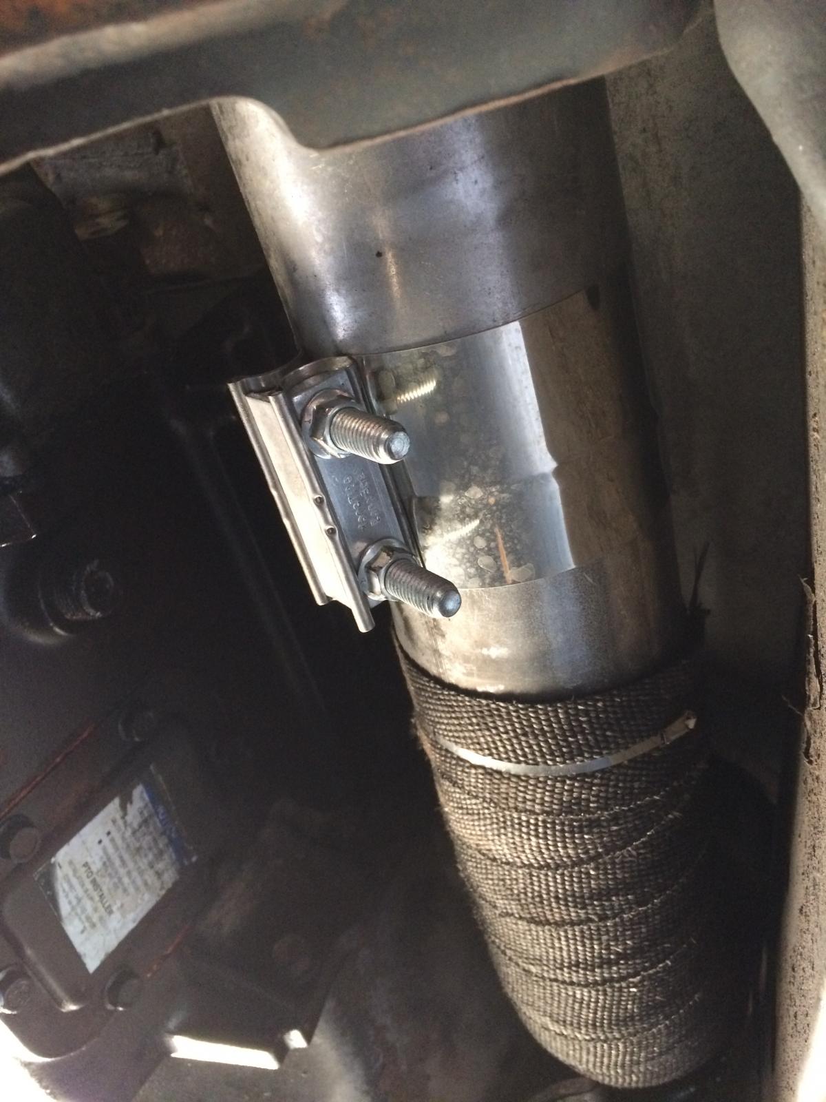
After getting your oil drain prepped, get the hacksaw out and cut off the exhaust pipe about 24 inches forward of the transmission cross member, this gives you room to mock everything up. I cut mine right where the 3.5" down pipe expanded to 4".
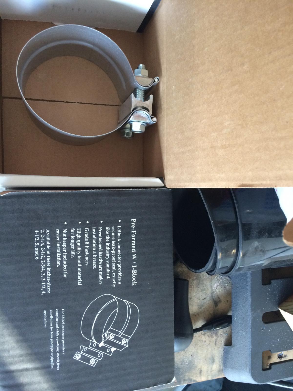
Tip # 2: go buy 1 or 2, 4" exhaust clamps (if you already have a 4" system) and if you are running a magnaflow system that has a 3.5 - 4 inch downpipe, you will need about 16 inches of 4" pipe to splice to your exhaust, unless you plan a new exhaust at the same time.

This is where I started mocking up the kit.
Problem #1 the waste gate actuator was in the way. Remove the actuator and with great finesse and care, Grind off the mount from the compressor housing.
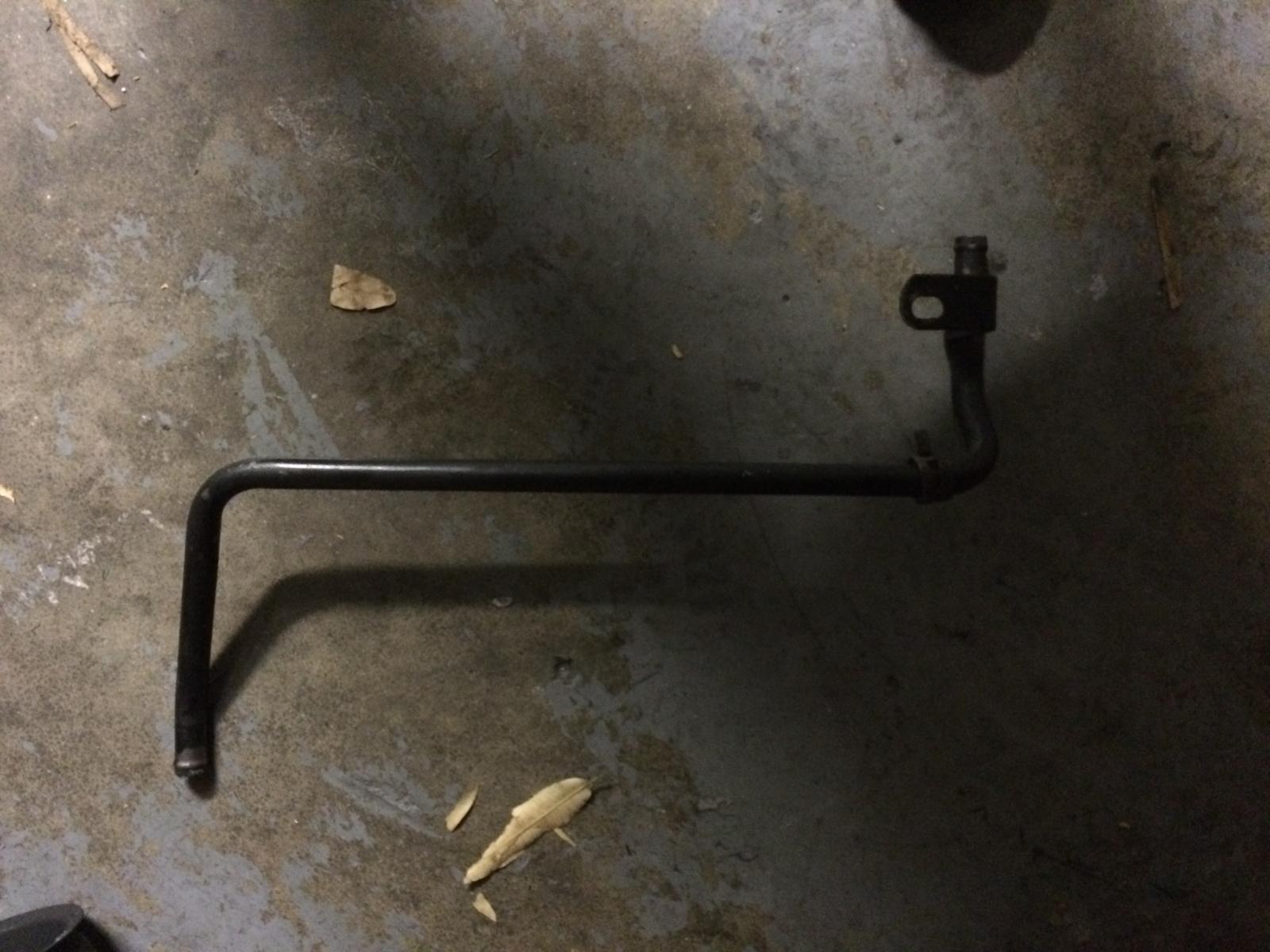
Problem #2, The heater pipe has a mount which bolts to the exhaust manifold. This does not fit with the manifold inverted.Its also in the way of the hot pipe. You have to options: Delete the pipe and replace with rubber hose, or Cut the mounting tab off. I cut the tab off, because I was being cheap.
.JPG.53914ec56a54d457e2f4bc9872ed8f39.JPG)
.JPG.45bf98f6649234876689f67e67e38405.JPG)
Now its time to start assembly. I fabricated a bracket to hold the waste gate actuator from 16 gauge plate steel from home cheapo. I used a piece of thin cardboard to template the T3 Bolt pattern, and measured the distance from the flat surface of the actuator mount on the comp housing, to the gate arm. using that measurement, I utilized a Drill press, Sawzall, Bench Vice, and Ball peen hammer to make my bracket. For rigidity, I started by bending the plate 90* in half, and then started on it with the sawzall. After I got it shaped right, I used my little mig welder to put a bead in the corner for extra strength. a bolt works just fine too. you will have to notch your bracket to give clearance for the HX35 oil drain.
I painted it with black header paint to look nice and put it off to the side.

]
Since you will have to grind off the actuator mount, now is a good time to paint your comp housing if you want to. I had my turbo and pipes come powder coated blue, so it made sense. I also had the T4 housing and center section ceramicoated, so I painted the HX35 T3 housing with header paint as well. Evil fab powder and ceramicoats for free, so just ask for it if you order a kit.
After bolting the manifold back in upside down, I installed the T3 spacer, and began final assembly.
Tip#3, it is really freaking hard to bolt the S366 up with the HX35 installed. I found it much easier to bolt them up on the garage bench, torque everything I had access to, and then set them in the engine bay as one piece.
.jpeg.e99a811d8511e7c23dc6b86ecc1064c7.jpeg)
.JPG.d8d5063c5398034058b9afe382c68b50.JPG)
.JPG.2bebab5f9bede7c659e1eb1b39a19bfc.JPG)
.JPG.02a722910b038cd268aeb5603873d8ff.JPG)
.JPG.e55204e079fd74b4eb266a06ab96ffd0.JPG)
Problem #3: If you do not grind off the actuator mount from the housing, you can't clock the housing correctly, and the HX oil feed line will not fit.
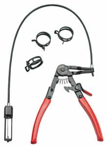
Problem #4: Go buy a spring clamp remover like the picture below. You will thank me later.
Remove the Comp housing, for grinding / painting, and its time to clock the center section of the HX35 for the oiling system. If you were smart about it you made sure to loosen your T3 housing clamps and break it loose before getting here. I didn't, so I took it all back apart to do so and then put it back together.
Tip#4: It may make more sense just to install the S366 with the HX35 T3 housing first, then install the HX35 center section. I didn't try it this way but I just realized it might make things easier.
After your HX35 center section is clocked, you can start modifying the oiling system. I clocked my HX center to about 12:30 position (Feed fitting position), which eased the tension on the line.
Now its time for the drain hoses. The trick here is not too long and not too short. the HX35 is pretty straight forward, since you are just deleting part of the solid pipe and replacing it with hose. The S366 is best tackled laying under the truck, where you should have access to everything. The hose there will curve a little but make sure it is not long enough to kink and flatten.
.JPG.a319c83897c17b6767f99b1d5952b2df.JPG)
.JPG.54d0e552ffcd2afc1d69fa4b67c8eb9e.JPG)
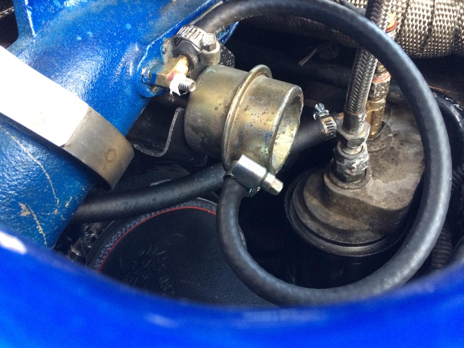
The feed line for the S366 is straight forward, but if you are using a your quad trans temp as a oil temp gauge, you will need some fancy 1/8" NPT parts to Tee off the Filter housing. Try routing the hose away from the hot pipe.
If you followed the directions, you are probably reinstalling your comp housing now and getting ready to start your truck.
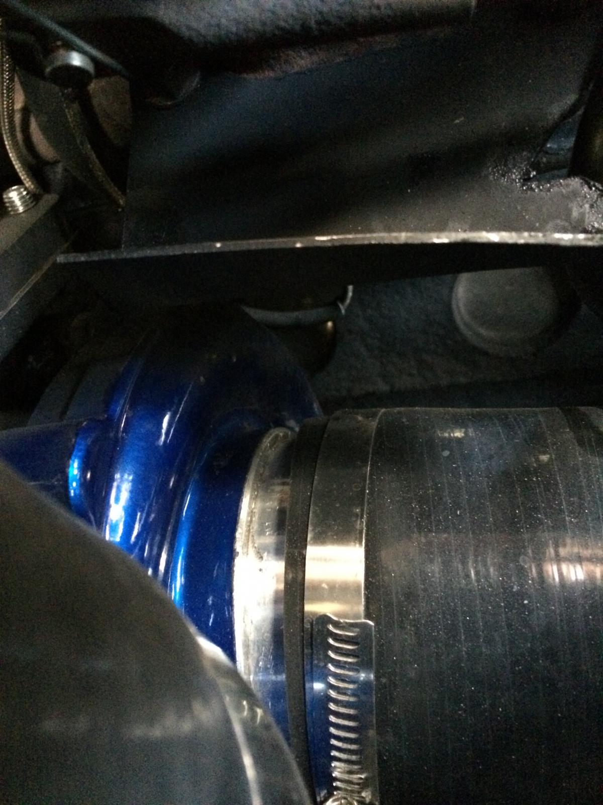
The spring clip on the HX35 is in my opinion the biggest pain in the *** of the entire project. I could not find a single set of snap ring pliers that could squeeze the SOB into place, which is why this install took two days (about 10 hours working time total). That being said, make damn sure you clock the housing right the first time. The outlet should point almost at 9:00. If you already installed the new silicone elbow and the cast comp elbow, its easy to clock the housing.
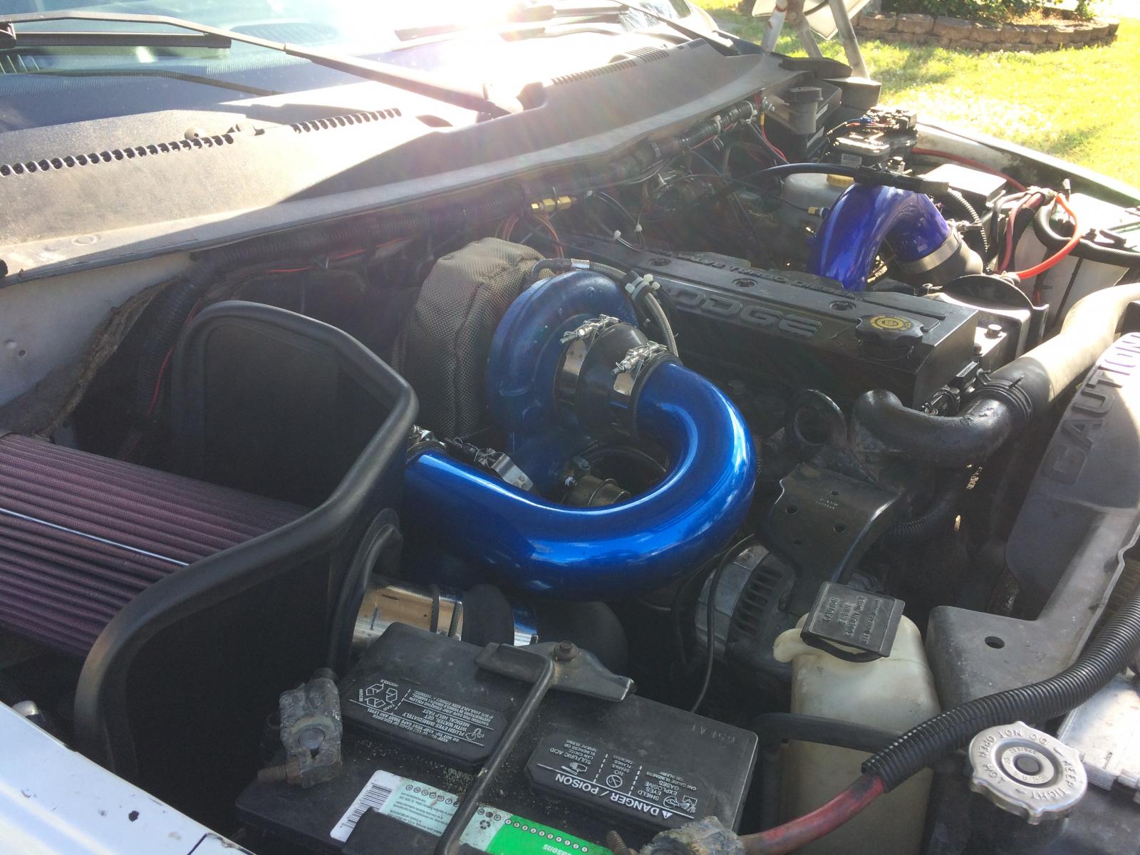
Finally, I started the truck per the instructions and followed the S366 pre oiling / break in instructions to the T!
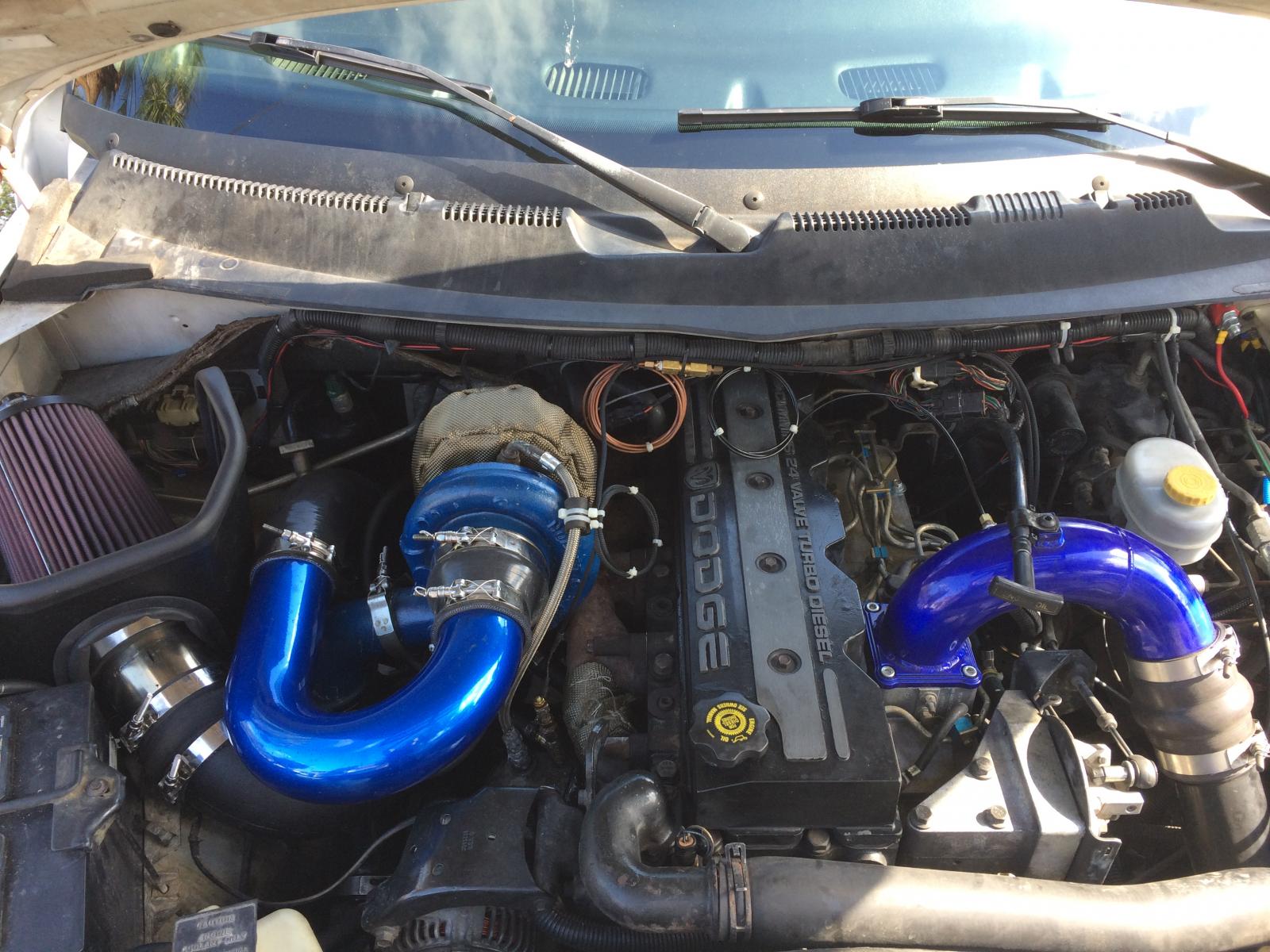
My only real complaint about this kit was the air filter setup. the kit comes with a small K&N cone filter, which goes right on the S366 and its close to the block in the hot air stream. I quickly used my old K&N Cold air intake and some Amazon IC parts to make a better setup.
I also ordered a T3 Turbo fiberglass heat shield, because I was nervous about the harness and the hood. The kit comes with the hot pipe and down pipe heat wrapped, which is nice.
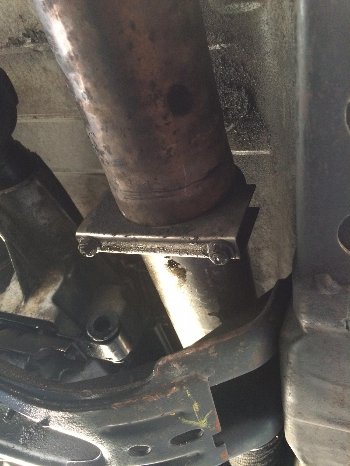
Two things I regret from the install: There is no support bracket for the S366, it just hangs off the hot pipe. I am not having issues, but it would have been easy to fabricate something while I had it apart. His larger kits include a better intake setup and a support bracket that goes to a header bolt. I also regret not heat wrapping my manifold while I had it off. I wrapped the section near the oil temp sensor, but that's it. I found a crack right in the middle of my manifold when I flipped it over, its not leaking for now, but I already sourced a replacement for a weekend that I'm bored.
Overall for 1500$ I am extremely happy, and the quality of the fabrication was very good. Waiting on my ARP stud kit and then I'll bump the boost up from 40 psi (quad limited) to 55 PSI, at least until I get valve springs.