
Grid Heater Bypass
Installing this bypass will allow you to manually control if and for how long you want to run the grid heaters when the ECM is commanding the grid heaters on. This will reduce the load on the alternator/charging system and in turn reduce the harmful AC voltage. This bypass will also keep the fault codes P0380 Intake Air Heater Relay #1 Control Circuit and P0382 Intake Air Heater Relay #2 Control Circuit from being set.
Parts needed:
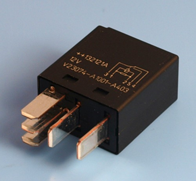
1. 2 micro relays, terminal 87 (5) normally open (NO) with suppressor
2. 2 5 watt / 20 ohm resistor
3. 1 single pole single throw switch (spst)
4. 2 male bullet and 2 female bullet connectors
5. 2 ring terminals
7. Rosin core solder
6. 10 female quick connect terminals
8. Heat shrink
9. ¼” protective wire cover
10. Electrical tape
11. Wire 18 AWG 4 different colors would be nice.
12. Optional 3 ATC fuse holders with 2 amp fuse
13. Something to mount the relays and resistors on.
14. 5 or more 6” zip ties
Micro relay
Putting it together
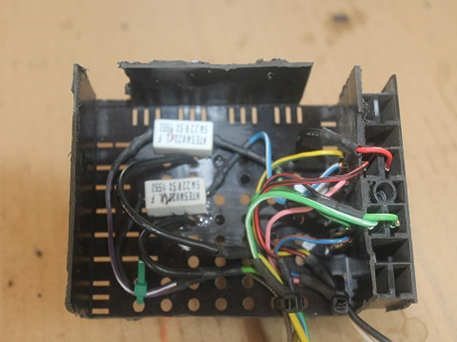
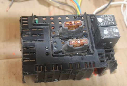
To mount the relays, resistors and fuses I used part of a used relay mount from a Volvo that I found. It was cut and modified to fit the parts.
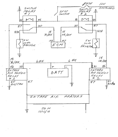
I didn’t want to cut the wire harness at the fire wall to access the solenoid trigger wires, yellow/black and orange/black, that goes from the Engine Control Module (ECM) to the grid heater control solenoids. I ran two wires to each solenoid connecting to the trigger wires with the male bullet connectors. This sent the trigger signal back to the control relays at terminal 30 (3). Two more wires were run from terminal 87 (5) of the control relay back to terminal 86 of the grid heater solenoids and connected the wires with the female bullet connectors.
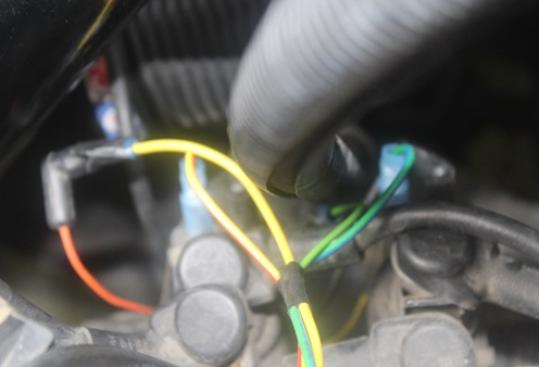
You can cover the wires from the firewall to the solenoids with the ¼” protective wire cover.
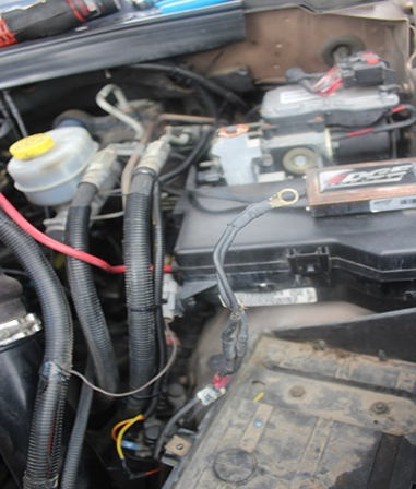
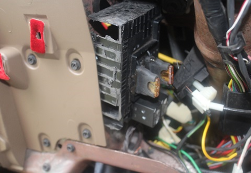
I installed the rely/resistor housing under the dash secured with a sheet metal screw and attached the ground wires to the dash sheet metal. For power I tapped into the fuse box on the left side of the dash and installed one of the ATC fuse holders and a 3 amp fuse. The control switch is installed into the left side of the steering column cover; I didn’t want it sticking out of the dash.
With the switch in the on position the control relay contacts 30 and 87 close and the grid heaters will operate normally giving heated air to the cylinders. The switch in the off position the control relay contacts 30 and 87a are closed and the ECM signal goes to the resistors mimicking the grid heater solenoids. No check engine light and reduced electrical load on the charging system. The switch can be operated on or off before during or after engine start up. Another added benefit is if your batteries are weak the grid heaters can be turned off saving power for the starter.
Written by:
J. Daniel Martin, Martin’s Mobile Maintenance
AKA IBMobile
12/21/2018
-
 1
1