


Grid Heater Bypass Simplified
The method described below is a simplified way of turning the grid heaters on and off when starting the engine and reducing the electrical load on the alternator without setting a P0380/P0382 code. The bypass solenoid is a 300amp rated Ford type starter solenoid. When both grid heaters are on there is about 180amp draw and after start up the draw is reduced to 90 amps so the bypass relay has a 50% plus overload safety factor.
Suggested Parts List
1 Standard Motor Parts starter solenoid SS-598 (bypass solenoid)
1 automotive on/off switch DC rated (your choice of style)
1 ATC fuse holder or fuse block (needed if not using fuse in PDC)
1 5amp fuse
13” 6AWG wire cable
5’ 18AWG wire red
5’ 18AWG wire blue
3’ 18AWG wire black
2 6AWG 5/16” copper wire ring terminal
3 22-18 AWG #10 ring terminal
2 #10X32X3/4” screw
2 #10X32 nut
4 #10 washer
4-5” of heat shrink (for the 8AWG cable terminals)
5’ ¼” plastic split wire loom
1 pack of 5-7” plastic ties
1 roll rosin core solder
Putting It Together
Disconnect both batteries; remove left (driver’s side) battery and battery tray. On the side of the battery tray fit the bypass solenoid and mark holes to be drilled; you may have to grind one side of the bypass solenoid mounting bracket to have it fit flush on the side of the battery tray. Drill 2 holes, 13/64”-7/32”, where marked on battery tray and mount the bypass solenoid with the #10 screws and nuts as shown below.
Note: the bypass solenoid is grounded through its body so a black ground wire, with a #10 ring terminal at each end, is attached to one of the mounting screws and the other end grounded to the body. Reinstall the battery tray.
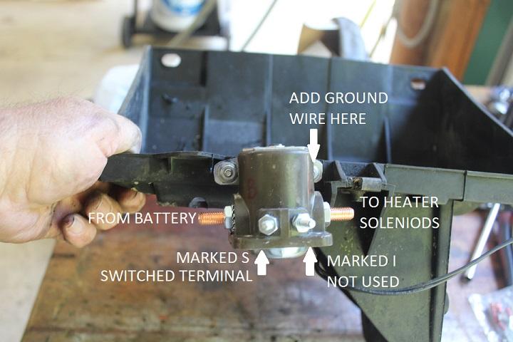
Left battery tray with solenoid attached.
Find a place in the cab where the switch type you chose will fit and be readily accessible. We used a rocker switch mounted in the kick panel below the steering column. For power you can tap into the fuse box on the left side of the dash. Find a terminal that has power only when the ignition key is in the on position. This is where you can add an ATC fuse holder with a 5amp fuse. Connect one end of the red wire to the fuse holder and the other end to the switch. Connect the blue wire to the other switch terminal and run it through the rubber grommet in the fire wall and with a #10 ring terminal connect it to the bypass solenoid terminal marked S; cover with ¼ “ split wire loom.
Make up the 6AWG cable (an 8AWG cable will work also) with the 5/16” copper ring terminals and heat shrink. I solder my cable ends on using a small butane torch but you can use a large cable end crimper. Be sure to index the orientation of the cable ends to the cable before attaching them so the ring terminals fit squarely on to the battery and solenoid.
The cables for the grid heat solenoid and battery power can now be attached to the bypass solenoid; the battery power cable to the firewall side of the bypass relay and the cables for the heater solenoid to the other side; reinstall the battery, connect all the terminals and reset the apps.
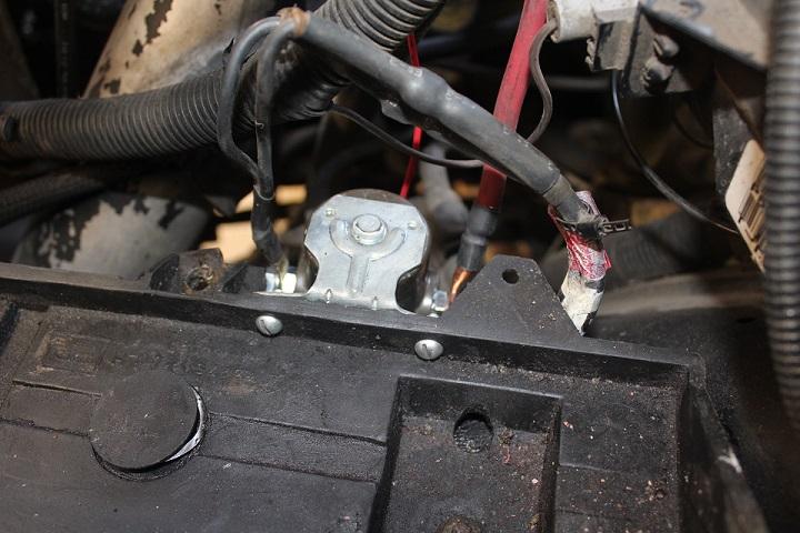
Left battery tray installed with bypass solenoid. Notice position of the cables.
Note: I have experienced a P1291” No temperature rise seen from intake heaters” when the temperature is below 35°F and the heaters are turned off right after starting the engine. I suggest leaving them on when first starting in cold weather for a minute or two.
Note: It was first suggested to use an SS-581 starter solenoid, this solenoid does not have a protective diode in it and may cause a voltage spike that could damage sensitive electronic components. A SS-598 solenoid should be used in its place.
This was installed with the help of JAG1 on his 2001 Ram 2500 diesel utility box work truck.
Written by:
J. Daniel Martin
AKA IBMobile
7/6/2019
-
 2
2