
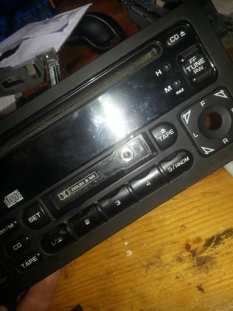
A few weeks ago I ordered some 3.5mm headphone jacks to try and wire up an AUX input into my radio. I did see a write-up on here for the Infinity system, but not the cd/cassette Chrysler radio with the number p04704383ah on the top cover. Finally got the parts in today to start in on this. Spent a bit of time looking and didn't find anything in regards to this radio.
|
|
This image has been resized. Click this bar to view the full image. |

| Report this image |
You will need
- Radio
- Headphone jack with internal Switch
- Soldering iron
- Heat Shrink
- 5 pieces of wire (3x6") (2x3")
- Phillips Screw Driver
- Multimeter
- SuperGlue
- Needle Nose
- Small Flat head screw driver
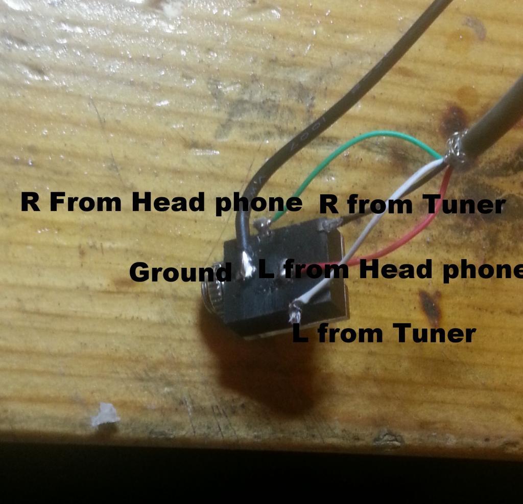
The headphone jacks I ordered have a left / Right / Ground / and a 2 pole single throw switch. This allows for you to route a signal, such as the radio, though the head phone jack when not in use and disable the signal coming for the radio when you put the headphone jack in. HERE is the jack I used. or searching on EBAY for "3.5 headphone jack switch". I am sure Radioshack has something similar, but I didn't have a chance to look. You will be responsible for understanding how the jack you ended up with works. Since different jacks will have different prongs etc I cannot tell you which prongs go where. Use a multimeter to determine what prongs do what when there is nothing plugged in and when there is something plugged in. The jack I bought has a clear cover which made it easy to see how it worked.
|
|
This image has been resized. Click this bar to view the full image. |
| Report this image |
I ended up using a larger wire and heat shrink but you get the idea behind the wiring.
First you need to disassemble the radio. Ensure to take note of how things go together because you will have to put it back together. If you are unsure about something take a picture of it. This DIY isn't meant to be a ste by step guide to disassemble the radio.
There are two screws holding the top cover on towards the top back left and right of the radio. Once those are removing you can pull off the cover.
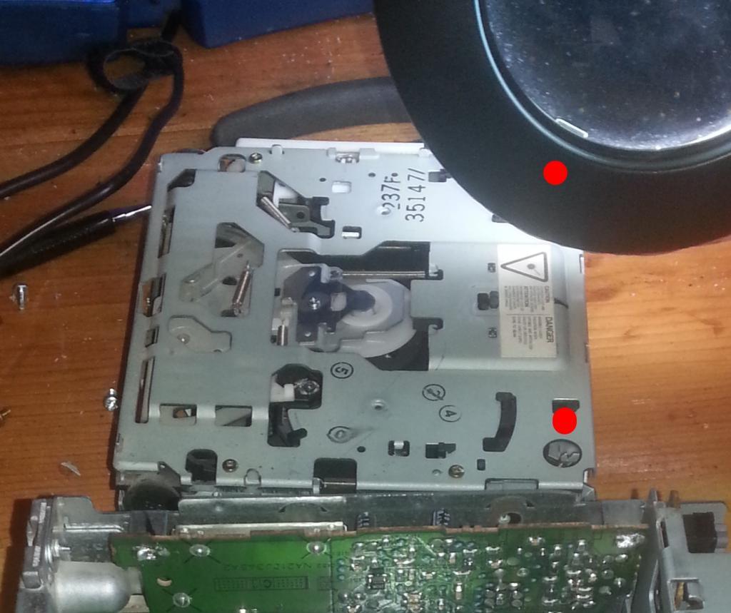
Next you need to remove the cd player. Do this by removing the phillips head screws holding the cd player in place. They are located towards the front of the unit on the left and right hand side on top. You can pull the cd player section straight up, take care to disconnect the ribbon cable under the cd player. Picture shows the approx location of the screws holding in the CD player
|
|
This image has been resized. Click this bar to view the full image. |
| Report this image |
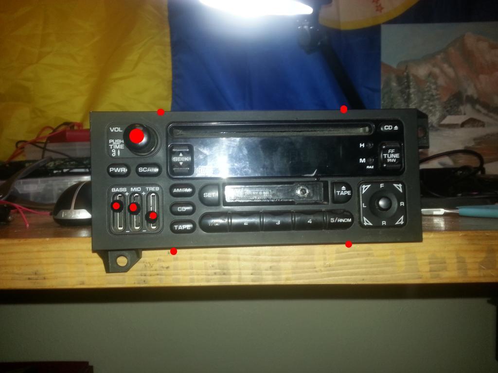
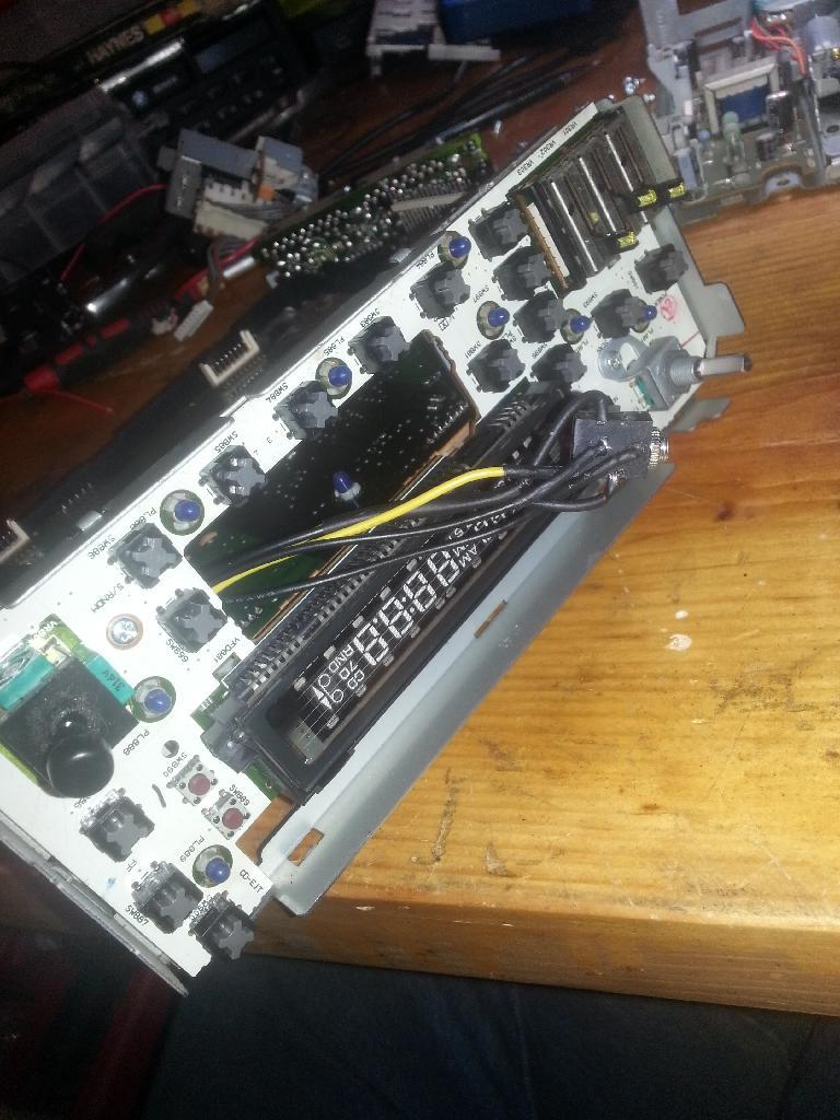
Next remove the faceplate of the radio. There are 2 screws on both the left and right hand side of the radio holding the plastic faceplate on. You will need to remove the volume knob and equalizer slider knobs. There are also 4 clips hold the bottom and top of the faceplate to the rest of the radio. Gently pop them loose.
|
|
This image has been resized. Click this bar to view the full image. |
| Report this image |
You will end up with this.
|
|
This image has been resized. Click this bar to view the full image. |
| Report this image |
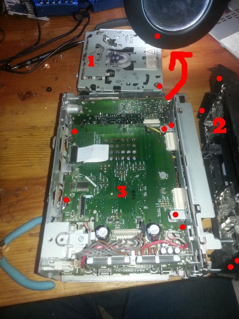
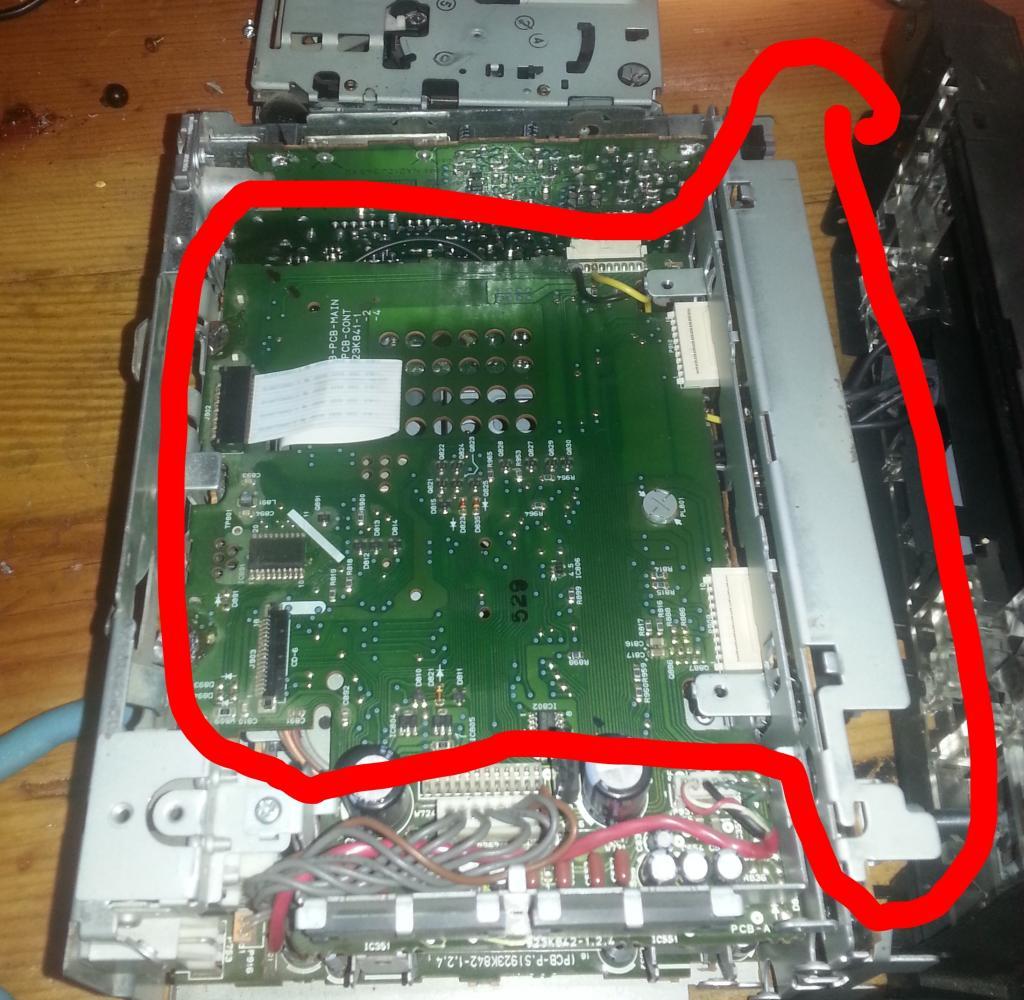
the middle board is the next to come out. It is what you will be altering to make the AUX input work. There are 4 bent metal fingers holding this board into place. They are locked in place with solder so you will need to use the soldering gun to melt the solder and bend the metal fingers straight. Take care to not pull it too hard. There are 5 different connections on this board that you need to pop loose to remove the board and one ribbon cable that connects to the tape deck. The red dots on the above picture around the edge of board #3 are the bent metal Fingers you need to straighten. You will also need to remove/bend out slightly the tuner module from the passenger side of the radio. It connects to the board you need to remove, but can't unless the tuner is swung out of the way.
The Front case section and board will come out as one piece
|
|
This image has been resized. Click this bar to view the full image. |
| Report this image |
|
|
This image has been resized. Click this bar to view the full image. |
| Report this image |
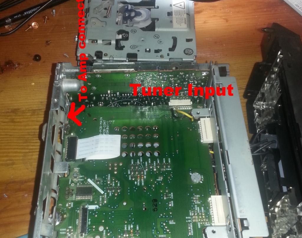
The main connections you will be working with are the Tuner input and the Amp input
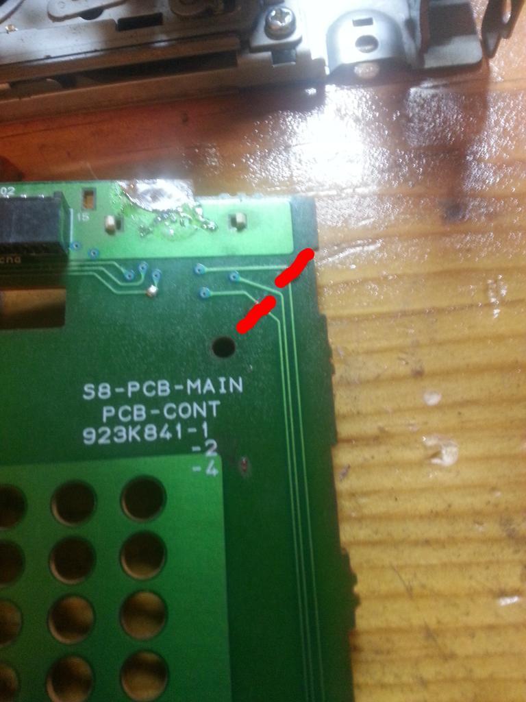
Once you get this board out use a small flat head to scratch off a section on the two circuits shown. You will need to ensure that there is no continuity between the amp input and tuner input connectors. Using the wire you will effectively put the headphone jack in place of that circuit. You can find the circuit in the back right hand side of the board, You can see brown marks from a sharpie in the above images. Don't scratch the ground circuit between the one you did scratch.
|
|
This image has been resized. Click this bar to view the full image. |
| Report this image |
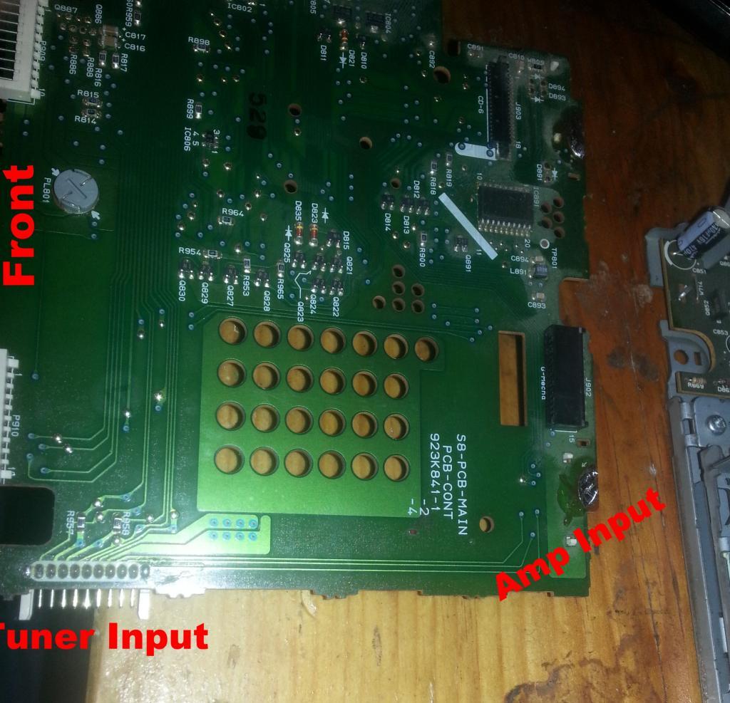
Next you will need to solder in the two short sections of the wires from your supplies to the Radio Tuner board input. The connector is located on the front of the radio to the right hand side if the radioface is pointed towards you.
|
|
This image has been resized. Click this bar to view the full image. |
| Report this image |
Here are the pins you want to connect your wires to. First is the Tuner input section on the front of the Radio.
|
|
This image has been resized. Click this bar to view the full image. |
| Report this image |
These short sections of the wire go to the switch poles on the headphone jack. Left and Right don't really matter as the amp controls which signals go to what speakers.
At this point if you have a quality radioshack soldering iron you will need to sand off the grime
|
|
This image has been resized. Click this bar to view the full image. |
| Report this image |
![rofl[1].gif](http://www.cumminsforum.com/forum/images/smilies/rofl%5B1%5D.gif "Roll On Floor")

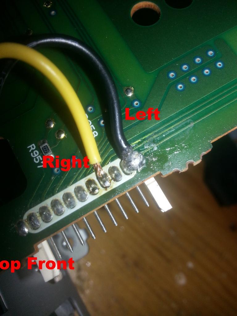
Next you need to connect the input prongs of the headphone jack and ground to the Amp input connector. to do this flip over the above board and solder on the L/R/G from the headphone jack. These prongs on the jack will be the ones that make direct connection to the actual jack.
|
|
This image has been resized. Click this bar to view the full image. |
| Report this image |
Once the poles in the headphone jack and the input for the headphone jack are wires onto the board test the amp input and tuner input for continuity between the two on both the right and left channels. There shouldn't be any continuity when something is plugged into the headphone jack. When the headphone jack is empty however there should be continuity, effectively passing the tuner signal through the headphone jack and into the amp. Once you verify that the jack is working as it should then you can move on.
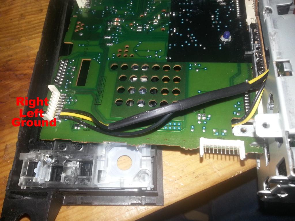
Next reinstall the board into the Radio case. Take care to line up all the connectors. This takes a little time, but isn't too tough. Rebend the metal fingers holding the board down. once the board is back in place route the jack and wires through the hole in the case for the tape deck.
|
|
This image has been resized. Click this bar to view the full image. |
| Report this image |
Once that is done you just have to drill a hole into the faceplate of the radio and mount your headphone jack. I chose to mount it in the tape deck flap since I don't think I own a tape anymore. If you choose this method you will need to superglue the tape deckflap closed. From my looking I couldn't find a location that my jack would actually fit, you might find a better place.
|
|
This image has been resized. Click this bar to view the full image. |
| Report this image |
Run the wires for the switch through the opening in the case for the tape deck. Insert your headphone jack into the hole you created and tighten it down.
At this point you will want to reinstall the cd player on top of the board you were working with. Take care to ensure that the wires you soldered into place are not being pinched. Once that is done reinstall the faceplate and the volume knob and equalizer knobs and the screws holding it in place.
Reinstall the top to the radio and any remaining screws and test.
Mine sounds great. plug in my phone when the radio is in tuner mode and it switches to Aux-in from my phone. 

![Thumbup19[1].gif](http://www.cumminsforum.com/forum/images/smilies/Thumbup19%5B1%5D.gif "Thumbs Up")
Let me know if there is any confusing bits.

