

1998.5 Power loss and shorts to ground.
- Replies 24
- Views 1.9k
- Created
- Last Reply
Top Posters In This Topic
-
Tractorman 11 posts
-
CH123 11 posts
-
Mopar1973Man 2 posts
A better way to browse. Learn more.
A full-screen app on your home screen with push notifications, badges and more.


Long time reader, first time poster. At my witts end. Bear with me while I bring you up to speed. I have a 1998.5 2500 automatic 2wd with roughly 155K miles. It was my grandfather's truck that I ended up with after his passing. It wasn't in good running condition, but after some TLC it was a dream. Work done includes - new turbo, ball joints, batteries, a/c, trailer wiring, tires, control arms, axle seals, belt, new suspension, cab lights, neutral safety switch, abs speed sensor, output speed sensor, and APPS.
Two years ago it went down on me one night while driving down the interstate, and I'm still trying to fix it. I was on cruise and suddenly lost power, not died but lost 95% of it's output. The truck still cranks and runs fine but will only idle or jump to 1400-1500 rpm. There is no in-between or past. In gear it will barely roll in my flat driveway. The truck has been with 3 mechanics without success and now it's back to me.
I found continuity between my positive and negative battery cables. I tracked to C1 of the PCM and verified I had continuity to ground from pins 4 and 22. I was also lacking ground continuity on C3 pin 28. I sent both the PCM and ECM to auto computer specialists and received them back this week. I reinstalled and all of those continuity issues have been resolved.
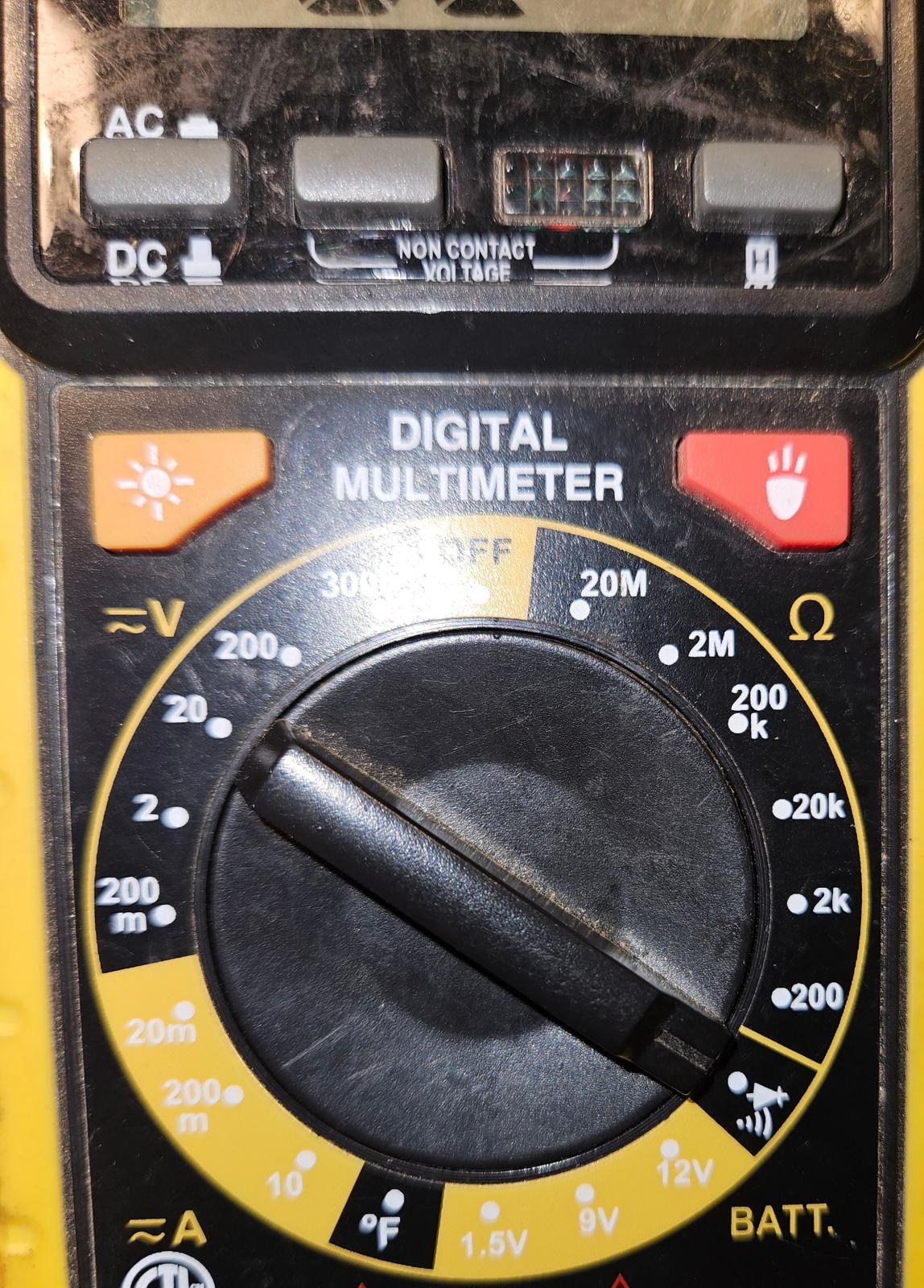
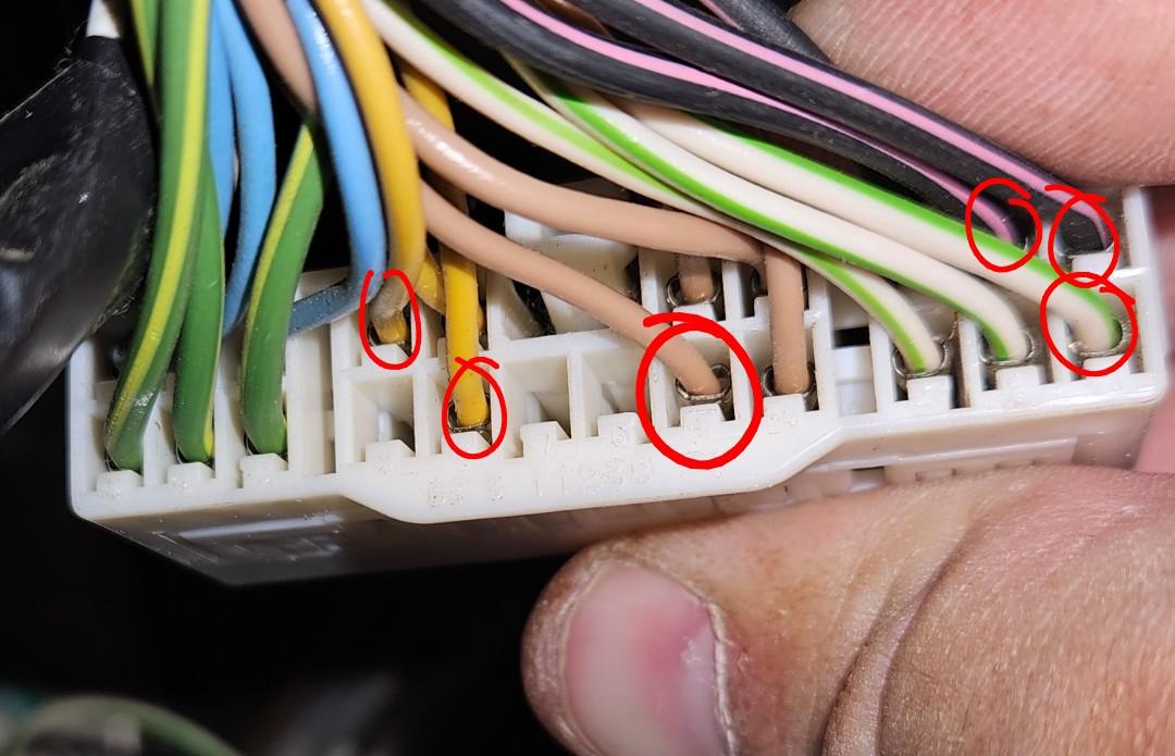
After installing the ECM and PCM my multimeter was still hooked up to my positive and negative battery terminals. I opened the drivers door and heard the continuity tone. I have since determined I have short to ground when either door is open or if the ignition is in run or the back position. I have yet to understand the relation of the door jam switches and the ignition switch. Confirmed it goes through the IOD fuse. Attempting to track the short I came to this connector near the steering column. I have been using the 1999 wiring diagrams for a while, but I am not able to find this connector with correct pin numbers. The pins circled have continuity to ground, but I'm not clear on their path from here.
Apologies for such a long post. Any guidance on where to go from here is appreciated.