


Me78569
Unpaid Member
-
Joined
-
Last visited
Everything posted by Me78569
-
Can you tell me the page number for the tablet of contents, missed that
-
update: I am not longer providing any support beyond what is found in this Article. I don't have the time to work with this stuff anymore., but thankfully Quadzilla is up and running again, you can find them at www.quadzillapower.com Hope This helped you guys out Nick Looking to buy a Quadzilla here is the links back to Quadzilla Power. 1998.5 to 2000 Dodge Ram Quadzilla Adrenaline $699.99 2001 Dodge Ram Quadzilla Adrenaline $699.99 2002 Dodge Ram Quadzilla Adrenaline $699.99 Tuners: Adrenaline standard The Quadzilla Adrenaline tuner, or Quad ADR, is a wiretap fueling , canbus fueling, and timing box for your 24v Cummins power turbo diesel in a Dodge ram application.. It is very customizable which makes it easy to tune for your specific needs. The Quadzilla Adrenaline or ADR will fuel to ~3500 RPM depending on the truck and the health of the Bosch VP44 injection pump for your Cummins power Truck. Custom Tunes can be found in this article covering both the old Quadzilla tuning and the New Quadzilla V2 Tuning. along with information in regards to how to tune. Base Tunes for Adrenaline and ZXT: The base tunes provided by Quadzilla can be found HERE A huge thanks to Jigabop for hosting and various members for sharing their saved files. Model numbers: ADR1000 98.5-00 model truck ADR1001 2001 model truck ADR1002 2002 model truck The Model number will be on the side of unit as seen above. The top tuner is a standard ADR for a 2002 model truck and the bottom is a 4k tuner for a 2001 Adrenaline 4k ADR4k00 98.5-00 Model truck ADR4k01 2001 Model truck ADR4k02 2002 Model truck The ADR 4k boxes allow the Revlimiter to be raised to ~4000 RPM. Think of this as a soft limit, not every truck will fuel to 4000 RPM as the VP44 has trouble at higher RPMS. Every truck will act different. The ADR 4k tuners are very well known for not being street friendly. Again I am pretty sure that the only physical difference in the 4k tuner between the model years is the jumper inside. The wiring harness pigtails for the MAP and Canbus should be the only difference. Adrenaline 4k VS Standard Adrenaline This Thread covers the actual physical differences between the 4k box and the standard ADR. Please read the entire thread if you have any questions in regards to upgrading a Standard ADR to a 4K ADR. There is a lot of good information in that thread that I am not going to move over to this thread at this point. ***Please note that it is not possible to turn a standard ADR tuner into a 4k tuner without changing the internal parts. To my knowledge no one has tried yet. ***Don't load the 4k tune from the tune library on a ADR1000,ADR1001, or ADR1002 model Boost Values reading Incorrectly If your boost values are not reading correct you may have to remove or insert a jumper within the box. The only real difference I am aware of between the actual physical standard ADR tuner between the model years is the jumper within *Not the 4k vs standard ADR differences*. If the jumper is installed the MAP values will read correctly for the 01-02 years but not right for the 98.5-00 years. Taking the jumper off from within will make the 98.5-00 MAP values read correctly, but not 01-02. You can see the jumper circled in the picture below. No Jumper installed 98.5-00 Jumper Installed: 01-02 years ** Sometime in Older adr boxes the jumper must be installed for 98.5-00 and not installed for 01-02 I have personally run a 01 unit on my 2000 without issues just by changing the internal jumper. Truck ran fine, tunes loaded fine. The difference really comes with the wiring harness pigtails that shipped with the unit as explained below. Harness The Different model year ADR tuners use the same box, BUT a different harness pigtails for the different years. Connectors Main harness Connector The main Harness Connector is a Delphi Connector. Information on it including part numbers for specfic parts can be found HERE Personally I order random parts like this from Mouser. MAP The ADR 1000 Uses a different MAP plug than the 01-02 style. I believe there is an adapter to convert from 00 style to 01-02 style, but it is very hard to come by. The 01 and 02 don't share the same MAP sensor pin layout but they use the same plug. There is a converter to use a 01 MAP to a 02 which I am pretty sure was included with the sale of ADR1001 and ADR1002 Tuners. This converter isn't as hard to find. You should be able to find this adapter from EDGE. The plugs are the same regardless of the of maker of the tuners. MAP sensor connector for the 98.5-00 Model Year 3 pin round It's hard to see but it is too cold and too windy for me to want to mess with it now. It will look very similar to the Fuel pressure connector, but the MAP will have a pigtail on it and the Fuel pressure will not. I believe the female MAP connector for the 98.5-00 years is a Delphi PN: 12065287 12065287 Delphi Connection Systems | Mouser I believe the male MAP connector for the 98.5-00 years is a Delphi PN: 410027 http://www.casperselectronics.com/st...oducts_id=1524 MAP for the 01 3 pin flat http://i879.photobucket.com/albums/ab360/me78569/Quadzilla/IMG_0535_zps240f198c.jpg MAP for a 02 uses a 3 pin flat, but has a different pinout than the 01. 02 map sensors use the same plug with a different pin out on the non-ground wires. Some trucks have been moved to 01 map sensors so check to see what map you have. Making your Own Map converter for the Quadzilla You will want to buy the right MAP sensor connectors listed above for your year truck. The wiring for the MAP converter is a little odd. This is due to the box doing boost fooling Dark Green, or the wire C coming from goes to the ECM side of the pigtail Green, or wire B goes to the MAP sensor side of the pigtail Red, or wire A goes to both the ECM side of the pigtail and the MAP sensor side of the pigtail, just splice them together as shown. Here is the wiring for the MAP sensor side of the pigtail, Notice the clip on the top of the plug. Here is the connector for the ECM side of the pigtail, notice the black and red on the top and green on the bottom. The Ground is shared between the female and male section Canbus / Datalink The Canbus/ Datalink also uses a different plug depending on the year, which there is an adapter for, I believe every ADR sold came with a Canbus adapter. Again this adapter should be sold by multiple companies as the plugs are the same regardless of the maker of the tuner. If you make your own just match the wiring as shown in the picture. Each plug is labeled A, B, and C The flat 3 pin canbus/data plug is a Delphi plug. Male connector assembly is PN: 12010717 Female connector assembly is PN: 12065287 the triangle data link is a DT04-3P. You can make your own or look for on Ebay or Craigslist. They can typically be found for $25-$35 Fuel pressure the Fuel pressure connector looks like this very similar to the MAP but it is a single connector on the lead wires. Color for the wires are Red, Yellow, and black I believe The FP uses a Delphi Connector also. PN: 12065287 12065287 Delphi Connection Systems | Mouser To summarize the above information, The wiring harness connector pigtails are specific between the ADR1000 and ADR1001/2 tuners for the MAP sensor. If you have a 1999 year truck, but a ADR1002 tuner you can run it just by using a ADR1000 harness and changing the jumper setting within. The wiring harness Pigtails are what you need to match to you year truck. There are adapters out there, but it is easier to find the right harness. You can also splice the harness and use the OEM connector found at a multitude of online vendors. Updating your Tune: **DO NOT CONNECT THE MODULE TO THE COMPUTER UNTIL INSTRUCTED TO DO SO** Windows 7 8 10 Windows Vista & Windows XP This software has been designed to work with Windows XP and MOST Vista machines, and does not work on Macintosh. If you have a Vista computer and the update does not work, an error log called “QZError.log” will be automatically saved Begin the download process by clicking the “download” button associated with the tuning file you would like to use from the Quadzilla update web page. Windows will ask you if you want to “run” or “save” the file. If you would like to keep the tuning file on your computer for future use choose “save” otherwise click “run”. If you choose to save the file, you will have to specify where you would like to save the file on your computer. You can save it anywhere you like, although saving to the “desktop” allows for easy access. After the download is complete, Windows will ask if you would like to “run” the file. Select “run” to open the X2 flash software. If this is not your first time to use the X2 Public Flasher, then you will not see the “Setup Wizard” load when the utility is started. Please skip to page 9. If this is your first time to use the X2 Public Flasher utility, please follow the proceeding steps: 1. Begin by clicking “run” after the download is complete. This will start the utility. You should see the “Setup Wizard” if this is your first time to run this program. This window will guide you through setting up the device drivers for your module. Once the “Setup Wizard” completes, you will not see it on subsequent uses of the X2 Public Flasher. 2. Click “Next” to allow the file copying process to begin. 3. Once all files are copied to your computer, you will be prompted to complete the steps necessary for the Hardware Wizard to begin. 4.After you have read the displayed instructions on this step, click “Next” to continue. When you see the following screen, you will need to connect the module to the computer and click “Next” so that the “Hardware Wizard” may begin. 5. When you see the “Welcome to the Found New Hardware Wizard”, select “No,not this time” or “Install the software automatically (recommended)”,and click “Next”. Please be patient as the “Found New Hardware Wizard” may take several minutes before reaching the next screen, depending on the speed of your computer. **If you do not see the “Found New Hardware Wizard” within a couple of minutes, disconnect the module from the computer, wait one second, then reconnect it to the computer.** 6. Once you have reached the below screen, select “Install the software automatically (Recommended)” and click “Next”. 7. Select the driver with a “Location” ending with “qz.inf” and click “Next”. **Not all computer systems will display this message, if you do not see this screen simply go to the next step** 8.You will then see the following “Hardware Installation” screen, simply choose “Continue Anyway”. 9. The “Found New Hardware Wizard” will then continue installing the necessary files to your computer. If at some point around this step you get an error message that reads, “Files needed. The file usbser.sys on windows drive cabinet is needed” GO TO STEP 14 OF THESE INSTRUCTIONS TO READ ABOUT HOW TO PROCEED. 10. When you see the following “Cannot Start this Hardware” message click “Finish” and disconnect the module from the computer. 11. Once the “Hardware Wizard” completes, click “Next” to proceed with the setup. 12. It is now time to disconnect the module from the computer. Once you have disconnected the module from the computer, click “Next”. 13. The following screen indicates the “Setup Wizard” has completed its tasks You may now click “Finish” to launch the “X2 Public Flasher”. 14. (This step only applies if a “files needed” error was encountered) A. Look at the error window that popped up saying that there are “files needed”. There should be a button that reads “BROWSE” click it. B. Another window will pop up that will allow you to manually select the file. At the top of this window there should be a pull down menu, click the small arrow symbol pointing down, and choose the folder labeled “WINDOWS” . C. In the “WINDOWS” folder scroll down until you see another folder that reads “system 32” and open it. D. Within the “system32” folder there should be another folder labeled “drivers” , open it. E. In the “drivers” folder there should be the file labeled “usbser.sys” , click on this file and click OK, the next to finish the hardware installation wizard. F. Revert to back to step 10 to finish the installation wizard. Loading a Tuning File to your Xzillaraider2, XZT+, M3, or Adrenaline Module Before beginning, make sure you have the Microsoft .NET Framework installed on your computer. It may be freely downloaded from: http://www.microsoft.com/downloads/details.aspx?FamilyID=0856EACB-4362-4B0D-8EDD-AAB15C5E04F5&displaylang=en Updating your module is accomplished by following three easy steps: 1. Start the X2 Public Flasher. Example: 2. Click “Update Module” and connect your module to the computer within ten seconds. 3. You can click “Get Information from Module” after programming to verify the tuning file has successfully been installed. Check the feature code and make sure it corresponds to the file that you desired to use. At this point you are ready to reinstall the module on your truck and enjoy your new tunes! Xzt http://i879.photobucket.com/albums/ab360/me78569/Quadzilla/XZT-plus_zpsa7a1d9ed.jpg The Xzt is a canbus and timing box. It connects to the Canbus for fueling and the MAP sensor for boost fooling and fueling based upon boost. It does the same hp as other Canbus tuners or ~65hp and ~125ft/lb along with a timing increase. HP numbers are pretty relative. It should be very similar to the Edge EZ I am not an expert on the XZT but I am pretty sure you need the correct XZT for your year truck/MAP sensor type. Again 98.5-00 uses the 3 pin round plug, 01 uses a 3 pin flat connector and 2002 uses a 3 pin flat connector with a different pin layout. Tunes for the XZT can be found on Jigabops hosted site found in numerous places in this post. Screens: PV2 If you want to update your PV2 please ensure that you are running the update from a Windows XP machine. If you run the update file from a windows 7 machine it will make your PV2 useless. The update can be found on Jigabops tune download site within the complete tune zip. Making your own PV2 Cable Big thanks to Cumminsdog and Tdoorn28 for posting pictures and PN for the needed parts. The 12 pin molex connector on the screen side of the wiring harness THIS is the male part! Again the picture is wrong but everything else should be right. 43020-1201 - MOLEX - PLUG & SOCKET CONNECTOR, PLUG, 12POS, 3MM | Newark element14 US [URL=http://s879.photobucket.com/user/me78569/media/Quadzilla/1510561_618106761586980_1710185498_n_zpsec810060.j pg.html] Here is the wiring pinout for the cable The 4 pin connector on the ADR harness side is a Duestch connector. It can be found HERE PN DT06-4S Ensure the wire orientation match that in this picture for the plug. PV1 PV1 Doesn't change power levels If your PV1 won't change power levels or accept custom tuning you likely need to run the PV1 upgrade program hosted on Jigabops Quadzilla site. It is VERY important to run the upgrade from a single core Windows XP 32bit machine. I ran the upgrade 10+ times from a single core 32bit windows 7 machine and always ended up with a PV1 that wouldn't change power levels. Once I ran it from a Windows XP machine it started working again. Flashing PV1 and PV2 screens from a Windows 7 Machine ***May or May Not Work*** The following steps allow you to upgrade/flash the PV1/2 using a Windows 7 machine provided it support Windows XP mode http://windows.microsoft.com/en-us/w...e-in-windows-7 I will help as much as I can with this part, but you will have to research installing this on your own. It is possible as I have done it on my personal 64 bit windows 7 machine for one VP! screen, but for another it did not work. I would recommend using a XP machine EVERYTIME, but if you cannot for one reason or another xp mode may work You must have windows 7 professional, Enterprise, or Ultimate. Your computer must also support CPU virtualization. You will need to download and install Windows Virtual PC http://www.microsoft.com/en-us/downl...s.aspx?id=3702 And XP mode http://windows.microsoft.com/en-us/w...e-in-windows-7 Once those are both downloaded you simply start the virtual windows xp then download and install Windows Framework 3.5 ( again I will try to help but installing Framework is your responsibility). Finally run the commander app with the PV1/2 plugged in, disregard when it says to unplug. Since it is a virtual environment the plugging in of the pulse is handled by forwarding that USB through the main machine, which you enable in the next step. Install the quadzilla drivers from the installer. once the drivers have been installed and the update program prompts you to plug in the PV1/2 then you enable the usb device, by clicking USB on the top menu bar and selecing the Pulse pv1/2. The pulse will show up and the windows pop up to install drivers will come up, This might take up to a minute for the usb to be patches through to the XP mode. Select install drivers automatically then click next. Click OK when the warning appears. When it finishes the install process you can click update now within the Quadzilla flasher program. Once the Quadzilla finishes updating your power up and down buttons should work again. Making your own PV1 Cable The cable for the PV1 is very similar to the PV2, but the screen side is actually soldiered to the board instead of a nice Molex connector. White: PAD 20 Black: PAD 21 Green: PAD 9 Red: PAD 12 These numbers were taken from my Commander screen which I am pretty sure is the same as a pv1 board. Take note of the spacing on the board if you do this yourself. Verify that my numbers match yours. The ADR side of the cable is a Duestch connector. It can be found HERE PN DT06-4S Ensure the wire orientation match that in this picture for the plug. Fixing your PV1 buttons The buttons on the PV1 are known for not working well. They can stick, not read etc. Here is a good write-up on how to install buttons for cheap. Very easy to do, works much better than the standard setup. Pulse Monitor Modification (no more bad buttons!) Big thanks to dknaks for this write-up Specs are pretty basic, 5mmx5mm should work. You want to make sure the switch is momentary. Iquad bluetooth All iquad bluetooth modules share the same PN so it is fair to assume that the bluetooth module can be from any year. The Iquad for Bluetooth is for Android only. Converting PV Screens from other model years PV2 From a purely speculation shot in the dark I will say that it MIGHT be possible to flash a different model year PV2 to work with the 2nd gen adr1000/1001/1002 boxes. From what I have seen with the PV1 screens I don't think Quad built the units with differences in the screens between the years. No one has tried that I am aware of using a PV2. I am more than willing to try if someone would provide me with a PV2. ****Again this is at your own risk**** PV1 See the below in regards to converting a Scout PV1 screen in the a working 2nd gen PV1. I am more than willing to try with other PV1's but again it is at your own risk. Converting a Commander/Scout screen into working with ADR To the best of my knowledge on the subject, the commander screen and scout screens are both early PV1 screens. I personally have a Scout screen that a friend had for his 2003 dodge SMS1002. Inside the board states it is a commander v1.3, but when you plug it into the computer the driver that is shown is for a PV1. However the tuner side of the cable is a 10 pin molex. Using an XP machine I have loaded the PV1 update found on Jigabops hosted site. The Commander screen took the update fine and now has power levels and custom tuning as a setting. ***Very important to note that you need an XP machine to run the PV1 or PV2 update that is hosted by Jigabop. If you run the update on a windows 7 machine or vista (I think) you will very likely ruin your PV screen. Seeing as we don't have the original firmware for them I don't know if we can fix it. You may be able to rerun the update from an XP and fix the issue, but I am not sure. I was able to soldier the correct wires into place on the board of my old commander screen to match the wiring from other PV1 screens Here it is working with the PV1 ADR software Sensors EGT Probe The Probe looks like this The connector on the harness looks like this. Also any K type thermocoupler will work with the Quadzilla. Cumminsdog was using an Isspro thermocoupler for ever with his. Again, any brand K-Type will work. DAP also sells one. Link is HERE Something like THIS Fuel Pressure Sender Isspro pressure sensors are supposed to work with the quadzilla. People have said they have in the past (actually tried it) and DAP told cumminsdog they were Isspro sensors. DAP site link to the Fuel pressure sender HERE The Issopro FP sender is PN: R89141, but I suggest contacting Jkidd at DAP first since they have verified that the part they sell works with the Quadzilla. Transmission Temp Sender The Quadzilla tranny temp sender is a Datcon 02022-00 Temp sensor. You can fine one HERE Other temp sensors may work, but I would stick with the part above as it matches the PN# on the Quadzilla Sender. So you jumped your truck without unplugging the ADR tuner? It is very important that you UNPLUG your Quadzilla tuner before jumping you truck. I can almost promise you that if you jump your truck without removing your Quadzilla tuner it will ruin your tuner. Typically after this happens the inside of your Quadzilla tuner will look like this. The big White thingy ( technical term for resistor) is a 1 OHM 10w Resistor with a %5 tolerance made by xicon PN: 280-CR10-1.0-rc. You can replace it and other burnt parts to try and fix the issue, or Ask/bribe ED to try and fix it for you. Mouser has them 280-CR10-1.0-RC Xicon | Mouser The Mosfet has a PN of IRF5210SPBF The thread having to do with Quadzilla stuff is HERE Adrenaline_Instructions.pdf Updating Instructions.doc Windows 7 Update.doc Windows Vista Unhandled Exception Error.doc If you find this helpful throw a donation my way. %95 of the things I do in regards to Quadzilla are to support the community and I receive no payment for the work. Thanks - Me78569 View full Cummins article
-
update: I am not longer providing any support beyond what is found in this Article. I don't have the time to work with this stuff anymore., but thankfully Quadzilla is up and running again, you can find them at www.quadzillapower.com Hope This helped you guys out Nick Looking to buy a Quadzilla here is the links back to Quadzilla Power. 1998.5 to 2000 Dodge Ram Quadzilla Adrenaline $699.99 2001 Dodge Ram Quadzilla Adrenaline $699.99 2002 Dodge Ram Quadzilla Adrenaline $699.99 Tuners: Adrenaline standard The Quadzilla Adrenaline tuner, or Quad ADR, is a wiretap fueling , canbus fueling, and timing box for your 24v Cummins power turbo diesel in a Dodge ram application.. It is very customizable which makes it easy to tune for your specific needs. The Quadzilla Adrenaline or ADR will fuel to ~3500 RPM depending on the truck and the health of the Bosch VP44 injection pump for your Cummins power Truck. Custom Tunes can be found in this article covering both the old Quadzilla tuning and the New Quadzilla V2 Tuning. along with information in regards to how to tune. Base Tunes for Adrenaline and ZXT: The base tunes provided by Quadzilla can be found HERE A huge thanks to Jigabop for hosting and various members for sharing their saved files. Model numbers: ADR1000 98.5-00 model truck ADR1001 2001 model truck ADR1002 2002 model truck The Model number will be on the side of unit as seen above. The top tuner is a standard ADR for a 2002 model truck and the bottom is a 4k tuner for a 2001 Adrenaline 4k ADR4k00 98.5-00 Model truck ADR4k01 2001 Model truck ADR4k02 2002 Model truck The ADR 4k boxes allow the Revlimiter to be raised to ~4000 RPM. Think of this as a soft limit, not every truck will fuel to 4000 RPM as the VP44 has trouble at higher RPMS. Every truck will act different. The ADR 4k tuners are very well known for not being street friendly. Again I am pretty sure that the only physical difference in the 4k tuner between the model years is the jumper inside. The wiring harness pigtails for the MAP and Canbus should be the only difference. Adrenaline 4k VS Standard Adrenaline This Thread covers the actual physical differences between the 4k box and the standard ADR. Please read the entire thread if you have any questions in regards to upgrading a Standard ADR to a 4K ADR. There is a lot of good information in that thread that I am not going to move over to this thread at this point. ***Please note that it is not possible to turn a standard ADR tuner into a 4k tuner without changing the internal parts. To my knowledge no one has tried yet. ***Don't load the 4k tune from the tune library on a ADR1000,ADR1001, or ADR1002 model Boost Values reading Incorrectly If your boost values are not reading correct you may have to remove or insert a jumper within the box. The only real difference I am aware of between the actual physical standard ADR tuner between the model years is the jumper within *Not the 4k vs standard ADR differences*. If the jumper is installed the MAP values will read correctly for the 01-02 years but not right for the 98.5-00 years. Taking the jumper off from within will make the 98.5-00 MAP values read correctly, but not 01-02. You can see the jumper circled in the picture below. No Jumper installed 98.5-00 Jumper Installed: 01-02 years ** Sometime in Older adr boxes the jumper must be installed for 98.5-00 and not installed for 01-02 I have personally run a 01 unit on my 2000 without issues just by changing the internal jumper. Truck ran fine, tunes loaded fine. The difference really comes with the wiring harness pigtails that shipped with the unit as explained below. Harness The Different model year ADR tuners use the same box, BUT a different harness pigtails for the different years. Connectors Main harness Connector The main Harness Connector is a Delphi Connector. Information on it including part numbers for specfic parts can be found HERE Personally I order random parts like this from Mouser. MAP The ADR 1000 Uses a different MAP plug than the 01-02 style. I believe there is an adapter to convert from 00 style to 01-02 style, but it is very hard to come by. The 01 and 02 don't share the same MAP sensor pin layout but they use the same plug. There is a converter to use a 01 MAP to a 02 which I am pretty sure was included with the sale of ADR1001 and ADR1002 Tuners. This converter isn't as hard to find. You should be able to find this adapter from EDGE. The plugs are the same regardless of the of maker of the tuners. MAP sensor connector for the 98.5-00 Model Year 3 pin round It's hard to see but it is too cold and too windy for me to want to mess with it now. It will look very similar to the Fuel pressure connector, but the MAP will have a pigtail on it and the Fuel pressure will not. I believe the female MAP connector for the 98.5-00 years is a Delphi PN: 12065287 12065287 Delphi Connection Systems | Mouser I believe the male MAP connector for the 98.5-00 years is a Delphi PN: 410027 http://www.casperselectronics.com/st...oducts_id=1524 MAP for the 01 3 pin flat http://i879.photobucket.com/albums/ab360/me78569/Quadzilla/IMG_0535_zps240f198c.jpg MAP for a 02 uses a 3 pin flat, but has a different pinout than the 01. 02 map sensors use the same plug with a different pin out on the non-ground wires. Some trucks have been moved to 01 map sensors so check to see what map you have. Making your Own Map converter for the Quadzilla You will want to buy the right MAP sensor connectors listed above for your year truck. The wiring for the MAP converter is a little odd. This is due to the box doing boost fooling Dark Green, or the wire C coming from goes to the ECM side of the pigtail Green, or wire B goes to the MAP sensor side of the pigtail Red, or wire A goes to both the ECM side of the pigtail and the MAP sensor side of the pigtail, just splice them together as shown. Here is the wiring for the MAP sensor side of the pigtail, Notice the clip on the top of the plug. Here is the connector for the ECM side of the pigtail, notice the black and red on the top and green on the bottom. The Ground is shared between the female and male section Canbus / Datalink The Canbus/ Datalink also uses a different plug depending on the year, which there is an adapter for, I believe every ADR sold came with a Canbus adapter. Again this adapter should be sold by multiple companies as the plugs are the same regardless of the maker of the tuner. If you make your own just match the wiring as shown in the picture. Each plug is labeled A, B, and C The flat 3 pin canbus/data plug is a Delphi plug. Male connector assembly is PN: 12010717 Female connector assembly is PN: 12065287 the triangle data link is a DT04-3P. You can make your own or look for on Ebay or Craigslist. They can typically be found for $25-$35 Fuel pressure the Fuel pressure connector looks like this very similar to the MAP but it is a single connector on the lead wires. Color for the wires are Red, Yellow, and black I believe The FP uses a Delphi Connector also. PN: 12065287 12065287 Delphi Connection Systems | Mouser To summarize the above information, The wiring harness connector pigtails are specific between the ADR1000 and ADR1001/2 tuners for the MAP sensor. If you have a 1999 year truck, but a ADR1002 tuner you can run it just by using a ADR1000 harness and changing the jumper setting within. The wiring harness Pigtails are what you need to match to you year truck. There are adapters out there, but it is easier to find the right harness. You can also splice the harness and use the OEM connector found at a multitude of online vendors. Updating your Tune: **DO NOT CONNECT THE MODULE TO THE COMPUTER UNTIL INSTRUCTED TO DO SO** Windows 7 8 10 Windows Vista & Windows XP This software has been designed to work with Windows XP and MOST Vista machines, and does not work on Macintosh. If you have a Vista computer and the update does not work, an error log called “QZError.log” will be automatically saved Begin the download process by clicking the “download” button associated with the tuning file you would like to use from the Quadzilla update web page. Windows will ask you if you want to “run” or “save” the file. If you would like to keep the tuning file on your computer for future use choose “save” otherwise click “run”. If you choose to save the file, you will have to specify where you would like to save the file on your computer. You can save it anywhere you like, although saving to the “desktop” allows for easy access. After the download is complete, Windows will ask if you would like to “run” the file. Select “run” to open the X2 flash software. If this is not your first time to use the X2 Public Flasher, then you will not see the “Setup Wizard” load when the utility is started. Please skip to page 9. If this is your first time to use the X2 Public Flasher utility, please follow the proceeding steps: 1. Begin by clicking “run” after the download is complete. This will start the utility. You should see the “Setup Wizard” if this is your first time to run this program. This window will guide you through setting up the device drivers for your module. Once the “Setup Wizard” completes, you will not see it on subsequent uses of the X2 Public Flasher. 2. Click “Next” to allow the file copying process to begin. 3. Once all files are copied to your computer, you will be prompted to complete the steps necessary for the Hardware Wizard to begin. 4.After you have read the displayed instructions on this step, click “Next” to continue. When you see the following screen, you will need to connect the module to the computer and click “Next” so that the “Hardware Wizard” may begin. 5. When you see the “Welcome to the Found New Hardware Wizard”, select “No,not this time” or “Install the software automatically (recommended)”,and click “Next”. Please be patient as the “Found New Hardware Wizard” may take several minutes before reaching the next screen, depending on the speed of your computer. **If you do not see the “Found New Hardware Wizard” within a couple of minutes, disconnect the module from the computer, wait one second, then reconnect it to the computer.** 6. Once you have reached the below screen, select “Install the software automatically (Recommended)” and click “Next”. 7. Select the driver with a “Location” ending with “qz.inf” and click “Next”. **Not all computer systems will display this message, if you do not see this screen simply go to the next step** 8.You will then see the following “Hardware Installation” screen, simply choose “Continue Anyway”. 9. The “Found New Hardware Wizard” will then continue installing the necessary files to your computer. If at some point around this step you get an error message that reads, “Files needed. The file usbser.sys on windows drive cabinet is needed” GO TO STEP 14 OF THESE INSTRUCTIONS TO READ ABOUT HOW TO PROCEED. 10. When you see the following “Cannot Start this Hardware” message click “Finish” and disconnect the module from the computer. 11. Once the “Hardware Wizard” completes, click “Next” to proceed with the setup. 12. It is now time to disconnect the module from the computer. Once you have disconnected the module from the computer, click “Next”. 13. The following screen indicates the “Setup Wizard” has completed its tasks You may now click “Finish” to launch the “X2 Public Flasher”. 14. (This step only applies if a “files needed” error was encountered) A. Look at the error window that popped up saying that there are “files needed”. There should be a button that reads “BROWSE” click it. B. Another window will pop up that will allow you to manually select the file. At the top of this window there should be a pull down menu, click the small arrow symbol pointing down, and choose the folder labeled “WINDOWS” . C. In the “WINDOWS” folder scroll down until you see another folder that reads “system 32” and open it. D. Within the “system32” folder there should be another folder labeled “drivers” , open it. E. In the “drivers” folder there should be the file labeled “usbser.sys” , click on this file and click OK, the next to finish the hardware installation wizard. F. Revert to back to step 10 to finish the installation wizard. Loading a Tuning File to your Xzillaraider2, XZT+, M3, or Adrenaline Module Before beginning, make sure you have the Microsoft .NET Framework installed on your computer. It may be freely downloaded from: http://www.microsoft.com/downloads/details.aspx?FamilyID=0856EACB-4362-4B0D-8EDD-AAB15C5E04F5&displaylang=en Updating your module is accomplished by following three easy steps: 1. Start the X2 Public Flasher. Example: 2. Click “Update Module” and connect your module to the computer within ten seconds. 3. You can click “Get Information from Module” after programming to verify the tuning file has successfully been installed. Check the feature code and make sure it corresponds to the file that you desired to use. At this point you are ready to reinstall the module on your truck and enjoy your new tunes! Xzt http://i879.photobucket.com/albums/ab360/me78569/Quadzilla/XZT-plus_zpsa7a1d9ed.jpg The Xzt is a canbus and timing box. It connects to the Canbus for fueling and the MAP sensor for boost fooling and fueling based upon boost. It does the same hp as other Canbus tuners or ~65hp and ~125ft/lb along with a timing increase. HP numbers are pretty relative. It should be very similar to the Edge EZ I am not an expert on the XZT but I am pretty sure you need the correct XZT for your year truck/MAP sensor type. Again 98.5-00 uses the 3 pin round plug, 01 uses a 3 pin flat connector and 2002 uses a 3 pin flat connector with a different pin layout. Tunes for the XZT can be found on Jigabops hosted site found in numerous places in this post. Screens: PV2 If you want to update your PV2 please ensure that you are running the update from a Windows XP machine. If you run the update file from a windows 7 machine it will make your PV2 useless. The update can be found on Jigabops tune download site within the complete tune zip. Making your own PV2 Cable Big thanks to Cumminsdog and Tdoorn28 for posting pictures and PN for the needed parts. The 12 pin molex connector on the screen side of the wiring harness THIS is the male part! Again the picture is wrong but everything else should be right. 43020-1201 - MOLEX - PLUG & SOCKET CONNECTOR, PLUG, 12POS, 3MM | Newark element14 US [URL=http://s879.photobucket.com/user/me78569/media/Quadzilla/1510561_618106761586980_1710185498_n_zpsec810060.j pg.html] Here is the wiring pinout for the cable The 4 pin connector on the ADR harness side is a Duestch connector. It can be found HERE PN DT06-4S Ensure the wire orientation match that in this picture for the plug. PV1 PV1 Doesn't change power levels If your PV1 won't change power levels or accept custom tuning you likely need to run the PV1 upgrade program hosted on Jigabops Quadzilla site. It is VERY important to run the upgrade from a single core Windows XP 32bit machine. I ran the upgrade 10+ times from a single core 32bit windows 7 machine and always ended up with a PV1 that wouldn't change power levels. Once I ran it from a Windows XP machine it started working again. Flashing PV1 and PV2 screens from a Windows 7 Machine ***May or May Not Work*** The following steps allow you to upgrade/flash the PV1/2 using a Windows 7 machine provided it support Windows XP mode http://windows.microsoft.com/en-us/w...e-in-windows-7 I will help as much as I can with this part, but you will have to research installing this on your own. It is possible as I have done it on my personal 64 bit windows 7 machine for one VP! screen, but for another it did not work. I would recommend using a XP machine EVERYTIME, but if you cannot for one reason or another xp mode may work You must have windows 7 professional, Enterprise, or Ultimate. Your computer must also support CPU virtualization. You will need to download and install Windows Virtual PC http://www.microsoft.com/en-us/downl...s.aspx?id=3702 And XP mode http://windows.microsoft.com/en-us/w...e-in-windows-7 Once those are both downloaded you simply start the virtual windows xp then download and install Windows Framework 3.5 ( again I will try to help but installing Framework is your responsibility). Finally run the commander app with the PV1/2 plugged in, disregard when it says to unplug. Since it is a virtual environment the plugging in of the pulse is handled by forwarding that USB through the main machine, which you enable in the next step. Install the quadzilla drivers from the installer. once the drivers have been installed and the update program prompts you to plug in the PV1/2 then you enable the usb device, by clicking USB on the top menu bar and selecing the Pulse pv1/2. The pulse will show up and the windows pop up to install drivers will come up, This might take up to a minute for the usb to be patches through to the XP mode. Select install drivers automatically then click next. Click OK when the warning appears. When it finishes the install process you can click update now within the Quadzilla flasher program. Once the Quadzilla finishes updating your power up and down buttons should work again. Making your own PV1 Cable The cable for the PV1 is very similar to the PV2, but the screen side is actually soldiered to the board instead of a nice Molex connector. White: PAD 20 Black: PAD 21 Green: PAD 9 Red: PAD 12 These numbers were taken from my Commander screen which I am pretty sure is the same as a pv1 board. Take note of the spacing on the board if you do this yourself. Verify that my numbers match yours. The ADR side of the cable is a Duestch connector. It can be found HERE PN DT06-4S Ensure the wire orientation match that in this picture for the plug. Fixing your PV1 buttons The buttons on the PV1 are known for not working well. They can stick, not read etc. Here is a good write-up on how to install buttons for cheap. Very easy to do, works much better than the standard setup. Pulse Monitor Modification (no more bad buttons!) Big thanks to dknaks for this write-up Specs are pretty basic, 5mmx5mm should work. You want to make sure the switch is momentary. Iquad bluetooth All iquad bluetooth modules share the same PN so it is fair to assume that the bluetooth module can be from any year. The Iquad for Bluetooth is for Android only. Converting PV Screens from other model years PV2 From a purely speculation shot in the dark I will say that it MIGHT be possible to flash a different model year PV2 to work with the 2nd gen adr1000/1001/1002 boxes. From what I have seen with the PV1 screens I don't think Quad built the units with differences in the screens between the years. No one has tried that I am aware of using a PV2. I am more than willing to try if someone would provide me with a PV2. ****Again this is at your own risk**** PV1 See the below in regards to converting a Scout PV1 screen in the a working 2nd gen PV1. I am more than willing to try with other PV1's but again it is at your own risk. Converting a Commander/Scout screen into working with ADR To the best of my knowledge on the subject, the commander screen and scout screens are both early PV1 screens. I personally have a Scout screen that a friend had for his 2003 dodge SMS1002. Inside the board states it is a commander v1.3, but when you plug it into the computer the driver that is shown is for a PV1. However the tuner side of the cable is a 10 pin molex. Using an XP machine I have loaded the PV1 update found on Jigabops hosted site. The Commander screen took the update fine and now has power levels and custom tuning as a setting. ***Very important to note that you need an XP machine to run the PV1 or PV2 update that is hosted by Jigabop. If you run the update on a windows 7 machine or vista (I think) you will very likely ruin your PV screen. Seeing as we don't have the original firmware for them I don't know if we can fix it. You may be able to rerun the update from an XP and fix the issue, but I am not sure. I was able to soldier the correct wires into place on the board of my old commander screen to match the wiring from other PV1 screens Here it is working with the PV1 ADR software Sensors EGT Probe The Probe looks like this The connector on the harness looks like this. Also any K type thermocoupler will work with the Quadzilla. Cumminsdog was using an Isspro thermocoupler for ever with his. Again, any brand K-Type will work. DAP also sells one. Link is HERE Something like THIS Fuel Pressure Sender Isspro pressure sensors are supposed to work with the quadzilla. People have said they have in the past (actually tried it) and DAP told cumminsdog they were Isspro sensors. DAP site link to the Fuel pressure sender HERE The Issopro FP sender is PN: R89141, but I suggest contacting Jkidd at DAP first since they have verified that the part they sell works with the Quadzilla. Transmission Temp Sender The Quadzilla tranny temp sender is a Datcon 02022-00 Temp sensor. You can fine one HERE Other temp sensors may work, but I would stick with the part above as it matches the PN# on the Quadzilla Sender. So you jumped your truck without unplugging the ADR tuner? It is very important that you UNPLUG your Quadzilla tuner before jumping you truck. I can almost promise you that if you jump your truck without removing your Quadzilla tuner it will ruin your tuner. Typically after this happens the inside of your Quadzilla tuner will look like this. The big White thingy ( technical term for resistor) is a 1 OHM 10w Resistor with a %5 tolerance made by xicon PN: 280-CR10-1.0-rc. You can replace it and other burnt parts to try and fix the issue, or Ask/bribe ED to try and fix it for you. Mouser has them 280-CR10-1.0-RC Xicon | Mouser The Mosfet has a PN of IRF5210SPBF The thread having to do with Quadzilla stuff is HERE Adrenaline_Instructions.pdf Updating Instructions.doc Windows 7 Update.doc Windows Vista Unhandled Exception Error.doc If you find this helpful throw a donation my way. %95 of the things I do in regards to Quadzilla are to support the community and I receive no payment for the work. Thanks - Me78569
-
Anywhere, I like Ebay, plug the PN in and see what you get back. a lot of time on OEM stuff someone will be selling the OEM part at a reduced costdue to them not needing it.
-
You can use this Spreadsheet to change the Gear ratio and tire size on your Cummins powered Truck You will see the typical peak power RPMS in green on the chart. To use this tool, enter your Trucks values into the Yellow Highlighted Fields. Tire Size is inputted into Field B5-D5 Truck type should be inputted to match the truck ( not useful yet) Options are "4wd Quad" "2wd Quad" "4wd Single" "2wd Single" Tire Type can be Offroad or Road ( not useful yet) Truck Weight can be any value ( not useful yet) Rear End Ratio can be any value Trans Type can be any trans from fields A:22 - H:22 **Spelling is critical** Use "47re" if you have a 48re Transfer Case can be "High" or "Low" for range select, Use this to edit the MPH values per gear. High can be any value to define Transfer case gearing Low can be any value to define Transfer case gearing Download HERE: mopar1973man gearing calc.xlsx This Spreadsheet will cover rear end gears of any custom amount, trannys listed are nv4550, nv5600, 47re, 48re, g56, 68rfe, as69rc. Thsi will so you the comparison between the gearing, tire size and tranny.
-
Can you use the bookmark tool on your phone within the embedded pdf? I don't have any Idevice so I can't look
-
here is the TSB https://mopar1973man.com/cummins/articles.html/24-valve-2nd-generation_50/51_engine/high-idle-switch/tsb-18-019-01-cold-idle-engine-warming-high-idle-enable-r421/
-
Mopar1973Man.Com High Idle / MPG Fooler Overhead Console Installation Ed Grafton sent me a Mopar1973Man High Idle switch for me to install into my overhead console, and do a write-up on it This is for guys that have no where else to put it due to too many gauges, or in the rare case like Jigabop who has too many options Ed Grafton extended the length of the wiring to allow for the wires to be run from the overhead console, under the headliner, down the A pillar, and into the engine bay. Whole install took about 2 hours. Tools And Supplies Needed - Drill - 2 1/8" whole saw - Smaller drill bit to drill the center ( 1/4" - 3/8" something small to ensure the center hole is in the right position) - Center Punch - Straight Edge/Ruler 1/16" - X Acto Knife - Wire cutters/Strippers - Soldering Iron - Heat Shrink - Lighter - Phillips Screw driver - Super glue or strong glue of choice - Zip Ties First thing you need to do is remove and unplug the overhead console. Do this by opening up the Garage Door Opener holder. You will see two clips that hold it onto the roof ( near the front). While pressing the clips pull down the front and slide it back. Next you need to remove the wiring and computer. Remote the Phillips screws hold in the lights (x4) and the Phillips screws holding in the Computer (x3) ****Notice the hole between the lights, this is where Mopar1973Man's High Idle wiring harness will be feed through. There is plenty of room between the console and the roof. Remove the faceplate from the Mopar1973Man High Idle Switch. Do this by removing the set screen in the knob and pulling the knob off. Remove the retaining nut and spacer. You will need to reinstall this later in the reverse order to take care to remember how it dissembled so you can reassemble it. Just looking at the Overhead Console you can see it fits about perfect right between the lights. That being said it is easy to see that if you don't measure the center of the lights you will mess up and break your lights and end up with an off center hole Measurements you want for the center of the plate is 1" vertical and 13/16" horizontal From the corners draw lines to find the center then verify with the above measurements. Measure and measure again. User a Center Punch to set the middle for the drill bit. ENSURE that you are perfectly centered. If this center is not perfect your faceplate WILL NOT FIT. After using the Center Punch, place the drill bit in the center to set the center hole for the hole saw. Again ensure that the drill is set perfectly in the middle BEFORE drilling. Next use the 2 1/8" Hole saw to cut out a circle for the faceplate to sit in. Drill slowly and stop as often as needed to reduce the amount of heat build up to prevent the plastic from melting too much. Verify that the hole you are cutting fits between the clear lens for the lights. Again it will be close, but it does fit. Above all take your time cutting the hole out. The slower you do it the better the end result will be. The plastic is bound to melt some, but you can take care of this with the help of an xacto knife. Once the hole is cut flip over the overhead console and verify that the clip section for the lens is intact. If you notice any breaks glue them back together. You may need to remove the lens to ensure you don't loose the functionality of the button press lights by gluing them shut. Using your faceplate and X-acto knife fit the faceplate into the cut hole. You may need to cut out some melted plastic etc to get the faceplate to fit good. Test the movement of the lens once the gauge is test fitted. Cut overhead console as needed to make the lens work. Once you are satisfied with the fitment/position of the faceplate glue it into place in the console. I choose to have the LED towards the back of the truck, but you can rotate the faceplate until it is in the position of your choosing. Glue from the back in a few locations slowly to ensure that no glue seeps to the front of the faceplate. Once the glue has dried then install the switch assembly into the faceplate in the reverse order of which you disassembled it. You will have to test the knob position, Far left is the off position. Once you have aligned the switch assembly tighten down the retaining nut that holds the faceplate. Reinstall the knob and verify again the turning the knob all the way counter-clockwise makes the knob point to the off position. Next reinstall the lights and computer by feeding Mopar1973Man High Idle wires through the OEM lights and reinstalling the Phillips screws in the reverse order of the above. Take your time when reinstalling to ensure that the harness fits and the lights click again when you press the lights. It will take a little work to get everything fitting good, but you will not need to cut anything on the light and button assembly. Gently bend Mopar1973Man's High Idle harness to contort in the same place as the OEM wires. Next you need to supply power to the LED light. Thankfully there is 12v power already in the overhead console. The pink wire coming off the plug is 12v and the black wire next to it is ground. The pink wire is a keyed power wire, the yellow wire is a power that is supplied based upon doors open and interior lights. Cut the Black and Pink wire with enough length to install heat shrink on the end. I cut them about 2" from the OEM plug. Strip the red and black wire that are together in the white conduit. Ensure that you DON'T cut the wires that go to the OEM plugs for ECT and IAT. There will be 4 wires in the harness that goes to the engine and 2 wires in the harness that you are cutting. Pre-install the heatshrink wrap onto the plug side of the cut wires. Solder together the cut pink wires and the red wire in Mopar1973Man's High Idle harness. Then Solder together the cut black wires and the black wire in Mopar1973Man's High Idle harness. Using a lighter heat up the heat shrink wrap to seal your solder splice. Use a zip tie to hold the wires together. Test the led in the switch by plugging the OEM connection and turning the High idle switch to any position. If it doesn't work use a multimeter to test for power to the OEM connector. Next remove your sun vizor by removing the 4 Phillips screws holding it to the roof. Feed the Mopar1973Man's High Idle ECT/IAT harness under the headliner by Gently pulling it down. It doesn't take much. Once you feed it through the console hole in the headliner you can pull it towards the A pillar. There is plenty of room for the harness to run between the window and the front of the headliner. You can slip it under the headliner easily. The A pillar cover will pull off by just popping it out. Use zip ties to the hold Mopar1973Man's High Idle harness to the OEM wiring running down the A pillar. Route the wiring through the dash and through the firewall into the Engine bay. Once at this point the install is the same as the other Types of installs for Mopar1973Man's High Idle switch. You will end up with something that looks like this. View full Cummins article
-
Mopar1973Man.Com High Idle / MPG Fooler Overhead Console Installation Ed Grafton sent me a Mopar1973Man High Idle switch for me to install into my overhead console, and do a write-up on it This is for guys that have no where else to put it due to too many gauges, or in the rare case like Jigabop who has too many options Ed Grafton extended the length of the wiring to allow for the wires to be run from the overhead console, under the headliner, down the A pillar, and into the engine bay. Whole install took about 2 hours. Tools And Supplies Needed - Drill - 2 1/8" whole saw - Smaller drill bit to drill the center ( 1/4" - 3/8" something small to ensure the center hole is in the right position) - Center Punch - Straight Edge/Ruler 1/16" - X Acto Knife - Wire cutters/Strippers - Soldering Iron - Heat Shrink - Lighter - Phillips Screw driver - Super glue or strong glue of choice - Zip Ties First thing you need to do is remove and unplug the overhead console. Do this by opening up the Garage Door Opener holder. You will see two clips that hold it onto the roof ( near the front). While pressing the clips pull down the front and slide it back. Next you need to remove the wiring and computer. Remote the Phillips screws hold in the lights (x4) and the Phillips screws holding in the Computer (x3) ****Notice the hole between the lights, this is where Mopar1973Man's High Idle wiring harness will be feed through. There is plenty of room between the console and the roof. Remove the faceplate from the Mopar1973Man High Idle Switch. Do this by removing the set screen in the knob and pulling the knob off. Remove the retaining nut and spacer. You will need to reinstall this later in the reverse order to take care to remember how it dissembled so you can reassemble it. Just looking at the Overhead Console you can see it fits about perfect right between the lights. That being said it is easy to see that if you don't measure the center of the lights you will mess up and break your lights and end up with an off center hole Measurements you want for the center of the plate is 1" vertical and 13/16" horizontal From the corners draw lines to find the center then verify with the above measurements. Measure and measure again. User a Center Punch to set the middle for the drill bit. ENSURE that you are perfectly centered. If this center is not perfect your faceplate WILL NOT FIT. After using the Center Punch, place the drill bit in the center to set the center hole for the hole saw. Again ensure that the drill is set perfectly in the middle BEFORE drilling. Next use the 2 1/8" Hole saw to cut out a circle for the faceplate to sit in. Drill slowly and stop as often as needed to reduce the amount of heat build up to prevent the plastic from melting too much. Verify that the hole you are cutting fits between the clear lens for the lights. Again it will be close, but it does fit. Above all take your time cutting the hole out. The slower you do it the better the end result will be. The plastic is bound to melt some, but you can take care of this with the help of an xacto knife. Once the hole is cut flip over the overhead console and verify that the clip section for the lens is intact. If you notice any breaks glue them back together. You may need to remove the lens to ensure you don't loose the functionality of the button press lights by gluing them shut. Using your faceplate and X-acto knife fit the faceplate into the cut hole. You may need to cut out some melted plastic etc to get the faceplate to fit good. Test the movement of the lens once the gauge is test fitted. Cut overhead console as needed to make the lens work. Once you are satisfied with the fitment/position of the faceplate glue it into place in the console. I choose to have the LED towards the back of the truck, but you can rotate the faceplate until it is in the position of your choosing. Glue from the back in a few locations slowly to ensure that no glue seeps to the front of the faceplate. Once the glue has dried then install the switch assembly into the faceplate in the reverse order of which you disassembled it. You will have to test the knob position, Far left is the off position. Once you have aligned the switch assembly tighten down the retaining nut that holds the faceplate. Reinstall the knob and verify again the turning the knob all the way counter-clockwise makes the knob point to the off position. Next reinstall the lights and computer by feeding Mopar1973Man High Idle wires through the OEM lights and reinstalling the Phillips screws in the reverse order of the above. Take your time when reinstalling to ensure that the harness fits and the lights click again when you press the lights. It will take a little work to get everything fitting good, but you will not need to cut anything on the light and button assembly. Gently bend Mopar1973Man's High Idle harness to contort in the same place as the OEM wires. Next you need to supply power to the LED light. Thankfully there is 12v power already in the overhead console. The pink wire coming off the plug is 12v and the black wire next to it is ground. The pink wire is a keyed power wire, the yellow wire is a power that is supplied based upon doors open and interior lights. Cut the Black and Pink wire with enough length to install heat shrink on the end. I cut them about 2" from the OEM plug. Strip the red and black wire that are together in the white conduit. Ensure that you DON'T cut the wires that go to the OEM plugs for ECT and IAT. There will be 4 wires in the harness that goes to the engine and 2 wires in the harness that you are cutting. Pre-install the heatshrink wrap onto the plug side of the cut wires. Solder together the cut pink wires and the red wire in Mopar1973Man's High Idle harness. Then Solder together the cut black wires and the black wire in Mopar1973Man's High Idle harness. Using a lighter heat up the heat shrink wrap to seal your solder splice. Use a zip tie to hold the wires together. Test the led in the switch by plugging the OEM connection and turning the High idle switch to any position. If it doesn't work use a multimeter to test for power to the OEM connector. Next remove your sun vizor by removing the 4 Phillips screws holding it to the roof. Feed the Mopar1973Man's High Idle ECT/IAT harness under the headliner by Gently pulling it down. It doesn't take much. Once you feed it through the console hole in the headliner you can pull it towards the A pillar. There is plenty of room for the harness to run between the window and the front of the headliner. You can slip it under the headliner easily. The A pillar cover will pull off by just popping it out. Use zip ties to the hold Mopar1973Man's High Idle harness to the OEM wiring running down the A pillar. Route the wiring through the dash and through the firewall into the Engine bay. Once at this point the install is the same as the other Types of installs for Mopar1973Man's High Idle switch. You will end up with something that looks like this.
-
Mopar1973Man Cummins High Idle Switch install Parts supplied: Switch x 1 Switch Harness x 1 Switch Face Sticker x 2 Tools Needed: Drill + 3/8” bit Cleaning Wipe Pliers Small Flathead Installing: First unplug the batteries to prevent any shorting while installing. The Mopar1973Man High Idle Switch can be mounted anywhere that the harness will reach. The Harness is a total of 10’ long. 4 feet of the harness is required under the hood. A good place to mount the Mopar1973man.com Cummins High Idle Switch is on the Kick Panel under the steering wheel. There are a total of 5 plugs on the harness. Mopar1973man Cummins High Idle Board Plug The 8 pin plug on the end plugs into the Mopar1973man Cummins High Idle Switch Board. It is keyed so it will only fit in one way. Don‘t plug this in until later. It is easier to install the Harness without the Board attached. IAT Plugs The 2 pin white plugs are the Intake Air Temp sensor plugs. Plug A plugs into the OEM Sensor on the Engine Plug B Plugs into the OEM wiring Harness You can see the OEM Plug/Sensor Location This is the rear Drivers side of the Engine ECT Plugs The 2 black 2 pin plugs are Engine Coolant Temp sensor plugs Plug A plugs into the OEM Sensor on the Engine Plug B Plugs into the OEM wiring Harness You can see the OEM Plug Location This is the Front Of the engine Mopar1973man Cummins High Idle Switch Faceplate Sticker The Sticker should be placed where you intend to install the Switch. ENSURE YOU CLEAN THE SURFACE THROUGHLY BEFORE APPLING THE STICKER. Ensure that there is at least 2” of clearance behind the switch location to prevent any possibility of shorting on the back of the switch. The center white section of the Faceplate should be drilled out once placed on the surface. This hole is what the switch will mount through. The High idle Switch will ship with 2 Stickers just in case one gets messed up during the install process. Power Leads: These power leads need to go to a fused 12v source, Red goes to 12v and black goes to ground. They power the LED on the Switch to give you a Green light in MPG mode and a Red / Orange light in high idle mode. The switch will work without these wires being connected. If you need more please contact Support@mopar1973man.com After plugging in the harness plugs to the OEM Sensors and OEM Harness, run the 8 pin Molex through the firewall. Gently pull the harness through the Firewall until there is no slack. Run the Harness to where you plan on installing the Mopar1973man Cummins High Idle Switch. Ensure to tie up any slack in the harness if it is hanging down. Remove the Knob on the switch by loosening the set screw on the back of the knob, then remove the lock nut on the switch. Install the Mopar1973man.com Cummins High Idle Switch through the hole drilled in the sticker. Reinstall the lock nut to hold the switch tightly. Reinstall the Knob and tighten the set screw. Plug the harness into the Mopar1973man Cummins High Idle Switch Board. Ensure the Switch position is lined up with the sticker face plate. Turning the switch all the way counter clock wise will be the off position. You can rotate the switch position vs the sticker then tighen the lock nut. I have also created a couple of videos showing the process. (Part 1) (Part 2) (Part 3) Installing the Mopar1973man.com high idle kit harness
-
Mechanical High Idle for All Cummins Trucks Here is another version of high idle you can produce for you dodge Cummins. A member over at Cummins Forum came to me with his version of high idle. Thank you WJBell for your information and allowing me to post here on my site... WJBell's High Idle Write Up Original Information is here. http://www.cumminsforum.com/forum/98-5-02-powertrain/111278-mechanical-high-idle-bomb-completed.html Since seeing Mopar Mans high idle I've been wanting to do something like it. I live in California so I really don't need it but for cold morning warms up's it's kind of nice. And if I idle it for a long time I've heard you can cake up the valves or warp cylinders. So I checked with three different dealers in my area and they all wanted $100+ to program the stock high idle. What I really wanted was the PTO idle controlled through cruise control but not available for my 2001. So... I decided to make my own PTO idle. I looked through some different posts and a couple guys did it with a high idle solenoid from Chevy's with a Rochester carb. So I went to pick & Pull today and picked one up for $7 off of a late 70's early 80's truck. Then I went to Ace hardware and picked up some 1/16 steel cable, a cable end stop and a thing to slip over the cable to tie it down. The one guy I saw mounted it on his APPS to push the throttle open, like an extended stop screw for the throttle. I didn't want to leave my APPS cover off or hack it up so I looked where I could mount it where the pedal pulls the cable under the dash. It wouldn't fit behind the pedal lever but there was a place where I could mount it where it pulled the top of the pedal where the cable was. And there is a bolt there in perfect position to mount the existing bracket on the solenoid. All I had to do is hacksaw off part of the bracket and it fit perfect. So I got a piece of 1/4 thick aluminum roughly about 1 3/4" long and 3/4" wide and mounted it to the end piece of the solenoid, drilling through them both and securing it with one machine screw. Then on the other end where the cable comes through I got a short, 3/4" long bolt (not sure what size but something that will fit into the aluminum bracket) and drilled it out though the center. Then drilled the aluminum bracket a little smaller than the bolt and force threaded the bolt into the bracket. (poor man's tap & die. Hey, it's aluminum!) So now the cable feeds in through the top of the bolt and you can fine tune the idle speed by tightening or backing out the bolt. So I ran the cable through, looped it around the pedal and tied it together with a 1/8" (can't remember what it's called) with an Allen set screw to tighten it down. I already had a switch wired through a relay up in my overhead sunglasses compartment so I just wired it to the solenoid. Started the truck up, flipped the switch and tapped the throttle and idle went up to about 1400. Turned off the switch and it dropped to normal. The solenoid doesn't have enough power to raise the idle by itself, you have to tap the throttle. After some adjustments, I got the high idle to right around 1100-1200. It's sweet. Start the truck, hit the switch and tap the throttle and you're at 1100 rpm. Turn off the switch and you're back to normal. There's no effect on the pedal, you can't feel any binding, etc. Works pretty sweet. Not bad for a couple hours work and under $20! I don't have 3 cylinders high idle but if I want that I'll just unplug three of the spark plugs. The part number for the solenoid is 1997461 and here's a list of cars it comes on. Hit your local pick & pull and you can pick one up for less than $10. 1977 : Chevrolet : Corvette : V8-350 5.7L OHV - notes: ROCHESTER EQPD - EXC CARB #17058232, 530 1977 : Chevrolet : Monte Carlo : V8-350 5.7L OHV - notes: ROCHESTER EQPD - EXC CARB #17058232, 530 1977 : Chevrolet : Camaro : V8-350 5.7L OHV - notes: ROCHESTER EQPD - EXC CARB #17058232, 530 1977 : Chevrolet : Camaro LT : V8-350 5.7L OHV - notes: ROCHESTER EQPD - EXC CARB #17058232, 530 1977 : Chevrolet : Camaro Z28 : V8-350 5.7L OHV - notes: ROCHESTER EQPD - EXC CARB #17058232, 530 1977 : Chevrolet : Full Size Chevrolet : V8-350 5.7L OHV - notes: ROCHESTER EQPD - EXC CARB #17058232, 530 1977 : Chevrolet : Caprice Classic : V8-350 5.7L OHV - notes: ROCHESTER EQPD - EXC CARB #17058232, 530 1977 : Chevrolet : Caprice Estate : V8-350 5.7L OHV - notes: ROCHESTER EQPD - EXC CARB #17058232, 530 1977 : Chevrolet : Impala : V8-350 5.7L OHV - notes: ROCHESTER EQPD - EXC CARB #17058232, 530 1977 : Chevrolet : Impala Custom : V8-350 5.7L OHV - notes: ROCHESTER EQPD - EXC CARB #17058232, 530 1977 : Chevrolet : Nova/Chevy II : V8-350 5.7L OHV - notes: ROCHESTER EQPD - EXC CARB #17058232, 530 1977 : Chevrolet : Nova : V8-350 5.7L OHV - notes: ROCHESTER EQPD - EXC CARB #17058232, 530 1977 : Chevrolet : Nova Concours : V8-350 5.7L OHV - notes: ROCHESTER EQPD - EXC CARB #17058232, 530 1977 : Chevrolet : Nova Custom : V8-350 5.7L OHV - notes: ROCHESTER EQPD - EXC CARB #17058232, 530 1977 : Chevrolet : Chevelle/Malibu : V8-350 5.7L OHV - notes: ROCHESTER EQPD - EXC CARB #17058232, 530 1977 : Chevrolet : Malibu : V8-350 5.7L OHV - notes: ROCHESTER EQPD - EXC CARB #17058232, 530 1977 : Chevrolet : Malibu CLassic : V8-350 5.7L OHV - notes: ROCHESTER EQPD - EXC CARB #17058232, 530 1978 : Chevrolet : Corvette : V8-350 5.7L OHV - notes: ROCHESTER EQPD - EXC CARB #17058232, 530 1978 : Chevrolet : Camaro : V8-350 5.7L OHV - notes: ROCHESTER EQPD - EXC CARB #17058232, 530 1978 : Chevrolet : Camaro LT : V8-350 5.7L OHV - notes: ROCHESTER EQPD - EXC CARB #17058232, 530 1978 : Chevrolet : Camaro Z28 : V8-350 5.7L OHV - notes: ROCHESTER EQPD - EXC CARB #17058232, 530 1978 : Chevrolet : Full Size Chevrolet : V8-350 5.7L OHV - notes: ROCHESTER EQPD - EXC CARB #17058232, 530 1978 : Chevrolet : Caprice : V8-350 5.7L OHV - notes: ROCHESTER EQPD - EXC CARB #17058232, 530 1978 : Chevrolet : Impala : V8-350 5.7L OHV - notes: ROCHESTER EQPD - EXC CARB #17058232, 530 1978 : Chevrolet : Nova/Chevy II : V8-350 5.7L OHV - notes: ROCHESTER EQPD - EXC CARB #17058232, 530 1978 : Chevrolet : Nova : V8-350 5.7L OHV - notes: ROCHESTER EQPD - EXC CARB #17058232, 530 1978 : Chevrolet : Nova Custom : V8-350 5.7L OHV - notes: ROCHESTER EQPD - EXC CARB #17058232, 530 1978 : Chevrolet : Chevelle/Malibu : V8-350 5.7L OHV - notes: ROCHESTER EQPD - EXC CARB #17058232, 530 1978 : Chevrolet : Malibu : V8-350 5.7L OHV - notes: ROCHESTER EQPD - EXC CARB #17058232, 530 1978 : Chevrolet : Malibu CLassic : V8-350 5.7L OHV - notes: ROCHESTER EQPD - EXC CARB #17058232, 530 1977 : Chevy Truck : Blazer Full Size : V8-350 5.7L - notes: 1978 : Chevy Truck : Blazer Full Size : V8-350 5.7L - notes: 1977 : Chevy Truck : C10, C20, C30, K10, K20, K30 Pickup : V8-350 5.7L - notes: 1977 : Chevy Truck : C10 1/2 Ton (2wd) Pickup : V8-350 5.7L - notes: 1977 : Chevy Truck : C20 3/4 Ton (2wd) Pickup : V8-350 5.7L - notes: 1977 : Chevy Truck : C30 1 Ton (2wd) Pickup : V8-350 5.7L - notes: 1977 : Chevy Truck : K10 1/2 Ton (4wd) Pickup : V8-350 5.7L - notes: 1977 : Chevy Truck : K20 3/4 Ton (4wd) Pickup : V8-350 5.7L - notes: 1977 : Chevy Truck : K30 1 Ton (4wd) Pickup : V8-350 5.7L - notes: 1977 : Chevy Truck : Suburban : V8-350 5.7L - notes: 1978 : Chevy Truck : C10, C20, C30, K10, K20, K30 Pickup : V8-350 5.7L - notes: 1978 : Chevy Truck : C10 1/2 Ton (2wd) Pickup : V8-350 5.7L - notes: 1978 : Chevy Truck : C20 3/4 Ton (2wd) Pickup : V8-350 5.7L - notes: 1978 : Chevy Truck : C30 1 Ton (2wd) Pickup : V8-350 5.7L - notes: 1978 : Chevy Truck : K10 1/2 Ton (4wd) Pickup : V8-350 5.7L - notes: 1978 : Chevy Truck : K20 3/4 Ton (4wd) Pickup : V8-350 5.7L - notes: 1978 : Chevy Truck : K30 1 Ton (4wd) Pickup : V8-350 5.7L - notes: 1978 : Chevy Truck : Suburban : V8-350 5.7L - notes: 1977 : Chevy Truck : El Camino : V8-350 5.7L - notes: EXC CARB #17058232, 530 1978 : Chevy Truck : El Camino : V8-350 5.7L - notes: EXC CARB #17058232, 530 1977 : Chevy Truck : G10, G20, G30 Vans : V8-350 5.7L - notes: 1977 : Chevy Truck : G10 1/2 Ton Van : V8-350 5.7L - notes: 1977 : Chevy Truck : G20 3/4 Ton Van : V8-350 5.7L - notes: 1977 : Chevy Truck : G30 1 Ton Van : V8-350 5.7L - notes: 1978 : Chevy Truck : G10, G20, G30 Vans : V8-350 5.7L - notes: 1978 : Chevy Truck : G10 1/2 Ton Van : V8-350 5.7L - notes: 1978 : Chevy Truck : G20 3/4 Ton Van : V8-350 5.7L - notes: 1978 : Chevy Truck : G30 1 Ton Van : V8-350 5.7L - notes: 1977 : GMC Truck : C+K 1500-3500 Pickup : V8-350 5.7L - notes: 1977 : GMC Truck : C1500 1/2 Ton (2wd) Pickup : V8-350 5.7L - notes: 1977 : GMC Truck : C2500 3/4 Ton (2wd) Pickup : V8-350 5.7L - notes: 1977 : GMC Truck : C3500 1 Ton (2wd) Pickup : V8-350 5.7L - notes: 1977 : GMC Truck : K1500 1/2 Ton (4wd) Pickup : V8-350 5.7L - notes: 1977 : GMC Truck : K2500 3/4 Ton (4wd) Pickup : V8-350 5.7L - notes: 1977 : GMC Truck : K3500 1 Ton (4wd) Pickup : V8-350 5.7L - notes: 1977 : GMC Truck : Suburban : V8-350 5.7L - notes: 1978 : GMC Truck : C+K 1500-3500 Pickup : V8-350 5.7L - notes: 1978 : GMC Truck : C1500 1/2 Ton (2wd) Pickup : V8-350 5.7L - notes: 1978 : GMC Truck : C2500 3/4 Ton (2wd) Pickup : V8-350 5.7L - notes: 1978 : GMC Truck : C3500 1 Ton (2wd) Pickup : V8-350 5.7L - notes: 1978 : GMC Truck : K1500 1/2 Ton (4wd) Pickup : V8-350 5.7L - notes: 1978 : GMC Truck : K2500 3/4 Ton (4wd) Pickup : V8-350 5.7L - notes: 1978 : GMC Truck : K3500 1 Ton (4wd) Pickup : V8-350 5.7L - notes: 1978 : GMC Truck : Suburban : V8-350 5.7L - notes: 1977 : GMC Truck : G1500-3500 Vans : V8-350 5.7L - notes: 1977 : GMC Truck : G1500 1/2 Ton Van : V8-350 5.7L - notes: 1977 : GMC Truck : G2500 3/4 Ton Van : V8-350 5.7L - notes: 1977 : GMC Truck : G3500 1 Ton Van : V8-350 5.7L - notes: 1978 : GMC Truck : G1500-3500 Vans : V8-350 5.7L - notes: 1978 : GMC Truck : G1500 1/2 Ton Van : V8-350 5.7L - notes: 1978 : GMC Truck : G2500 3/4 Ton Van : V8-350 5.7L - notes: 1978 : GMC Truck : G3500 1 Ton Van : V8-350 5.7L - notes: 1977 : GMC Truck : Jimmy/Yukon Full Size : V8-350 5.7L - notes: 1978 : GMC Truck : Jimmy/Yukon Full Size : V8-350 5.7L - notes: 1977 : GMC Truck : Sprint/Caballero : V8-350 5.7L - notes: EXC CARB #17058232, 530 1978 : GMC Truck : Sprint/Caballero : V8-350 5.7L - notes: EXC CARB #17058232, 530 1977 : Oldsmobile : Full Size Oldsmobile (Rwd) : V8-350 5.7L - notes: 4 BBL, CHEV ENG 1977 : Oldsmobile : 98 Regency : V8-350 5.7L - notes: 4 BBL, CHEV ENG 1977 : Oldsmobile : Custom Cruiser : V8-350 5.7L - notes: 4 BBL, CHEV ENG 1977 : Oldsmobile : Delta 88 : V8-350 5.7L - notes: 4 BBL, CHEV ENG 1977 : Oldsmobile : Delta 88 Royale : V8-350 5.7L - notes: 4 BBL, CHEV ENG 1977 : Oldsmobile : Luxury 98 : V8-350 5.7L - notes: 4 BBL, CHEV ENG 1977 : Oldsmobile : Omega : V8-350 5.7L - notes: CHEV ENG 1977 : Oldsmobile : Omega Brougham : V8-350 5.7L - notes: CHEV ENG 1977 : Oldsmobile : Omega F85 : V8-350 5.7L - notes: CHEV ENG View full Cummins article
-
Mechanical High Idle for All Cummins Trucks Here is another version of high idle you can produce for you dodge Cummins. A member over at Cummins Forum came to me with his version of high idle. Thank you WJBell for your information and allowing me to post here on my site... WJBell's High Idle Write Up Original Information is here. http://www.cumminsforum.com/forum/98-5-02-powertrain/111278-mechanical-high-idle-bomb-completed.html Since seeing Mopar Mans high idle I've been wanting to do something like it. I live in California so I really don't need it but for cold morning warms up's it's kind of nice. And if I idle it for a long time I've heard you can cake up the valves or warp cylinders. So I checked with three different dealers in my area and they all wanted $100+ to program the stock high idle. What I really wanted was the PTO idle controlled through cruise control but not available for my 2001. So... I decided to make my own PTO idle. I looked through some different posts and a couple guys did it with a high idle solenoid from Chevy's with a Rochester carb. So I went to pick & Pull today and picked one up for $7 off of a late 70's early 80's truck. Then I went to Ace hardware and picked up some 1/16 steel cable, a cable end stop and a thing to slip over the cable to tie it down. The one guy I saw mounted it on his APPS to push the throttle open, like an extended stop screw for the throttle. I didn't want to leave my APPS cover off or hack it up so I looked where I could mount it where the pedal pulls the cable under the dash. It wouldn't fit behind the pedal lever but there was a place where I could mount it where it pulled the top of the pedal where the cable was. And there is a bolt there in perfect position to mount the existing bracket on the solenoid. All I had to do is hacksaw off part of the bracket and it fit perfect. So I got a piece of 1/4 thick aluminum roughly about 1 3/4" long and 3/4" wide and mounted it to the end piece of the solenoid, drilling through them both and securing it with one machine screw. Then on the other end where the cable comes through I got a short, 3/4" long bolt (not sure what size but something that will fit into the aluminum bracket) and drilled it out though the center. Then drilled the aluminum bracket a little smaller than the bolt and force threaded the bolt into the bracket. (poor man's tap & die. Hey, it's aluminum!) So now the cable feeds in through the top of the bolt and you can fine tune the idle speed by tightening or backing out the bolt. So I ran the cable through, looped it around the pedal and tied it together with a 1/8" (can't remember what it's called) with an Allen set screw to tighten it down. I already had a switch wired through a relay up in my overhead sunglasses compartment so I just wired it to the solenoid. Started the truck up, flipped the switch and tapped the throttle and idle went up to about 1400. Turned off the switch and it dropped to normal. The solenoid doesn't have enough power to raise the idle by itself, you have to tap the throttle. After some adjustments, I got the high idle to right around 1100-1200. It's sweet. Start the truck, hit the switch and tap the throttle and you're at 1100 rpm. Turn off the switch and you're back to normal. There's no effect on the pedal, you can't feel any binding, etc. Works pretty sweet. Not bad for a couple hours work and under $20! I don't have 3 cylinders high idle but if I want that I'll just unplug three of the spark plugs. The part number for the solenoid is 1997461 and here's a list of cars it comes on. Hit your local pick & pull and you can pick one up for less than $10. 1977 : Chevrolet : Corvette : V8-350 5.7L OHV - notes: ROCHESTER EQPD - EXC CARB #17058232, 530 1977 : Chevrolet : Monte Carlo : V8-350 5.7L OHV - notes: ROCHESTER EQPD - EXC CARB #17058232, 530 1977 : Chevrolet : Camaro : V8-350 5.7L OHV - notes: ROCHESTER EQPD - EXC CARB #17058232, 530 1977 : Chevrolet : Camaro LT : V8-350 5.7L OHV - notes: ROCHESTER EQPD - EXC CARB #17058232, 530 1977 : Chevrolet : Camaro Z28 : V8-350 5.7L OHV - notes: ROCHESTER EQPD - EXC CARB #17058232, 530 1977 : Chevrolet : Full Size Chevrolet : V8-350 5.7L OHV - notes: ROCHESTER EQPD - EXC CARB #17058232, 530 1977 : Chevrolet : Caprice Classic : V8-350 5.7L OHV - notes: ROCHESTER EQPD - EXC CARB #17058232, 530 1977 : Chevrolet : Caprice Estate : V8-350 5.7L OHV - notes: ROCHESTER EQPD - EXC CARB #17058232, 530 1977 : Chevrolet : Impala : V8-350 5.7L OHV - notes: ROCHESTER EQPD - EXC CARB #17058232, 530 1977 : Chevrolet : Impala Custom : V8-350 5.7L OHV - notes: ROCHESTER EQPD - EXC CARB #17058232, 530 1977 : Chevrolet : Nova/Chevy II : V8-350 5.7L OHV - notes: ROCHESTER EQPD - EXC CARB #17058232, 530 1977 : Chevrolet : Nova : V8-350 5.7L OHV - notes: ROCHESTER EQPD - EXC CARB #17058232, 530 1977 : Chevrolet : Nova Concours : V8-350 5.7L OHV - notes: ROCHESTER EQPD - EXC CARB #17058232, 530 1977 : Chevrolet : Nova Custom : V8-350 5.7L OHV - notes: ROCHESTER EQPD - EXC CARB #17058232, 530 1977 : Chevrolet : Chevelle/Malibu : V8-350 5.7L OHV - notes: ROCHESTER EQPD - EXC CARB #17058232, 530 1977 : Chevrolet : Malibu : V8-350 5.7L OHV - notes: ROCHESTER EQPD - EXC CARB #17058232, 530 1977 : Chevrolet : Malibu CLassic : V8-350 5.7L OHV - notes: ROCHESTER EQPD - EXC CARB #17058232, 530 1978 : Chevrolet : Corvette : V8-350 5.7L OHV - notes: ROCHESTER EQPD - EXC CARB #17058232, 530 1978 : Chevrolet : Camaro : V8-350 5.7L OHV - notes: ROCHESTER EQPD - EXC CARB #17058232, 530 1978 : Chevrolet : Camaro LT : V8-350 5.7L OHV - notes: ROCHESTER EQPD - EXC CARB #17058232, 530 1978 : Chevrolet : Camaro Z28 : V8-350 5.7L OHV - notes: ROCHESTER EQPD - EXC CARB #17058232, 530 1978 : Chevrolet : Full Size Chevrolet : V8-350 5.7L OHV - notes: ROCHESTER EQPD - EXC CARB #17058232, 530 1978 : Chevrolet : Caprice : V8-350 5.7L OHV - notes: ROCHESTER EQPD - EXC CARB #17058232, 530 1978 : Chevrolet : Impala : V8-350 5.7L OHV - notes: ROCHESTER EQPD - EXC CARB #17058232, 530 1978 : Chevrolet : Nova/Chevy II : V8-350 5.7L OHV - notes: ROCHESTER EQPD - EXC CARB #17058232, 530 1978 : Chevrolet : Nova : V8-350 5.7L OHV - notes: ROCHESTER EQPD - EXC CARB #17058232, 530 1978 : Chevrolet : Nova Custom : V8-350 5.7L OHV - notes: ROCHESTER EQPD - EXC CARB #17058232, 530 1978 : Chevrolet : Chevelle/Malibu : V8-350 5.7L OHV - notes: ROCHESTER EQPD - EXC CARB #17058232, 530 1978 : Chevrolet : Malibu : V8-350 5.7L OHV - notes: ROCHESTER EQPD - EXC CARB #17058232, 530 1978 : Chevrolet : Malibu CLassic : V8-350 5.7L OHV - notes: ROCHESTER EQPD - EXC CARB #17058232, 530 1977 : Chevy Truck : Blazer Full Size : V8-350 5.7L - notes: 1978 : Chevy Truck : Blazer Full Size : V8-350 5.7L - notes: 1977 : Chevy Truck : C10, C20, C30, K10, K20, K30 Pickup : V8-350 5.7L - notes: 1977 : Chevy Truck : C10 1/2 Ton (2wd) Pickup : V8-350 5.7L - notes: 1977 : Chevy Truck : C20 3/4 Ton (2wd) Pickup : V8-350 5.7L - notes: 1977 : Chevy Truck : C30 1 Ton (2wd) Pickup : V8-350 5.7L - notes: 1977 : Chevy Truck : K10 1/2 Ton (4wd) Pickup : V8-350 5.7L - notes: 1977 : Chevy Truck : K20 3/4 Ton (4wd) Pickup : V8-350 5.7L - notes: 1977 : Chevy Truck : K30 1 Ton (4wd) Pickup : V8-350 5.7L - notes: 1977 : Chevy Truck : Suburban : V8-350 5.7L - notes: 1978 : Chevy Truck : C10, C20, C30, K10, K20, K30 Pickup : V8-350 5.7L - notes: 1978 : Chevy Truck : C10 1/2 Ton (2wd) Pickup : V8-350 5.7L - notes: 1978 : Chevy Truck : C20 3/4 Ton (2wd) Pickup : V8-350 5.7L - notes: 1978 : Chevy Truck : C30 1 Ton (2wd) Pickup : V8-350 5.7L - notes: 1978 : Chevy Truck : K10 1/2 Ton (4wd) Pickup : V8-350 5.7L - notes: 1978 : Chevy Truck : K20 3/4 Ton (4wd) Pickup : V8-350 5.7L - notes: 1978 : Chevy Truck : K30 1 Ton (4wd) Pickup : V8-350 5.7L - notes: 1978 : Chevy Truck : Suburban : V8-350 5.7L - notes: 1977 : Chevy Truck : El Camino : V8-350 5.7L - notes: EXC CARB #17058232, 530 1978 : Chevy Truck : El Camino : V8-350 5.7L - notes: EXC CARB #17058232, 530 1977 : Chevy Truck : G10, G20, G30 Vans : V8-350 5.7L - notes: 1977 : Chevy Truck : G10 1/2 Ton Van : V8-350 5.7L - notes: 1977 : Chevy Truck : G20 3/4 Ton Van : V8-350 5.7L - notes: 1977 : Chevy Truck : G30 1 Ton Van : V8-350 5.7L - notes: 1978 : Chevy Truck : G10, G20, G30 Vans : V8-350 5.7L - notes: 1978 : Chevy Truck : G10 1/2 Ton Van : V8-350 5.7L - notes: 1978 : Chevy Truck : G20 3/4 Ton Van : V8-350 5.7L - notes: 1978 : Chevy Truck : G30 1 Ton Van : V8-350 5.7L - notes: 1977 : GMC Truck : C+K 1500-3500 Pickup : V8-350 5.7L - notes: 1977 : GMC Truck : C1500 1/2 Ton (2wd) Pickup : V8-350 5.7L - notes: 1977 : GMC Truck : C2500 3/4 Ton (2wd) Pickup : V8-350 5.7L - notes: 1977 : GMC Truck : C3500 1 Ton (2wd) Pickup : V8-350 5.7L - notes: 1977 : GMC Truck : K1500 1/2 Ton (4wd) Pickup : V8-350 5.7L - notes: 1977 : GMC Truck : K2500 3/4 Ton (4wd) Pickup : V8-350 5.7L - notes: 1977 : GMC Truck : K3500 1 Ton (4wd) Pickup : V8-350 5.7L - notes: 1977 : GMC Truck : Suburban : V8-350 5.7L - notes: 1978 : GMC Truck : C+K 1500-3500 Pickup : V8-350 5.7L - notes: 1978 : GMC Truck : C1500 1/2 Ton (2wd) Pickup : V8-350 5.7L - notes: 1978 : GMC Truck : C2500 3/4 Ton (2wd) Pickup : V8-350 5.7L - notes: 1978 : GMC Truck : C3500 1 Ton (2wd) Pickup : V8-350 5.7L - notes: 1978 : GMC Truck : K1500 1/2 Ton (4wd) Pickup : V8-350 5.7L - notes: 1978 : GMC Truck : K2500 3/4 Ton (4wd) Pickup : V8-350 5.7L - notes: 1978 : GMC Truck : K3500 1 Ton (4wd) Pickup : V8-350 5.7L - notes: 1978 : GMC Truck : Suburban : V8-350 5.7L - notes: 1977 : GMC Truck : G1500-3500 Vans : V8-350 5.7L - notes: 1977 : GMC Truck : G1500 1/2 Ton Van : V8-350 5.7L - notes: 1977 : GMC Truck : G2500 3/4 Ton Van : V8-350 5.7L - notes: 1977 : GMC Truck : G3500 1 Ton Van : V8-350 5.7L - notes: 1978 : GMC Truck : G1500-3500 Vans : V8-350 5.7L - notes: 1978 : GMC Truck : G1500 1/2 Ton Van : V8-350 5.7L - notes: 1978 : GMC Truck : G2500 3/4 Ton Van : V8-350 5.7L - notes: 1978 : GMC Truck : G3500 1 Ton Van : V8-350 5.7L - notes: 1977 : GMC Truck : Jimmy/Yukon Full Size : V8-350 5.7L - notes: 1978 : GMC Truck : Jimmy/Yukon Full Size : V8-350 5.7L - notes: 1977 : GMC Truck : Sprint/Caballero : V8-350 5.7L - notes: EXC CARB #17058232, 530 1978 : GMC Truck : Sprint/Caballero : V8-350 5.7L - notes: EXC CARB #17058232, 530 1977 : Oldsmobile : Full Size Oldsmobile (Rwd) : V8-350 5.7L - notes: 4 BBL, CHEV ENG 1977 : Oldsmobile : 98 Regency : V8-350 5.7L - notes: 4 BBL, CHEV ENG 1977 : Oldsmobile : Custom Cruiser : V8-350 5.7L - notes: 4 BBL, CHEV ENG 1977 : Oldsmobile : Delta 88 : V8-350 5.7L - notes: 4 BBL, CHEV ENG 1977 : Oldsmobile : Delta 88 Royale : V8-350 5.7L - notes: 4 BBL, CHEV ENG 1977 : Oldsmobile : Luxury 98 : V8-350 5.7L - notes: 4 BBL, CHEV ENG 1977 : Oldsmobile : Omega : V8-350 5.7L - notes: CHEV ENG 1977 : Oldsmobile : Omega Brougham : V8-350 5.7L - notes: CHEV ENG 1977 : Oldsmobile : Omega F85 : V8-350 5.7L - notes: CHEV ENG
-
ugh. I hate the look of the links. can you use the bookmarks tool in the main PDF itself?
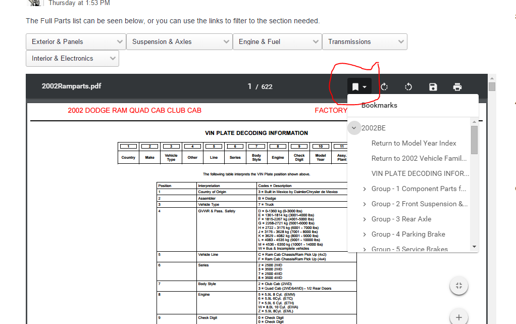
-
"i devices" dont like adobe and the embedded stuff. Not much we can do about it.
-
what kind of phone.
-
try again, I messed up the link.
-
Hey guys, I wanted to give you a heads up that we have created a Part Number Lookup tool in the new Articles. https://mopar1973man.com/cummins/articles.html/4th-generation/part-number-lookup-tool-4th-gen/ You can find a couple of different years and configurations in the above link. You can open up the year / model needed and use the drop down menu to jump around or use the bookmarks tool on the main page to jump around. We will add more documents as we get them, but most parts should span the years we have.
-
Hey guys, I wanted to give you a heads up that we have created a Part Number Lookup Tool using the new Articles Section https://mopar1973man.com/cummins/articles.html/3rd-generation/part-number-lookup-tool-3rd-gen/ You can find various 3rd Gen Years and different models. The drop down menu's will point to different sections, you can also use the Bookmarks icon on the main PDF to jump through the sections!
-
Hey guys, I just wanted to give you a heads up that we have created a parts lookup tool using the new articles section! This will take a few minutes to load for the first time, but once it does you should be happy with how it works. You can use the drop down menu's to browse through the sections. You can also use the bookmarks function in the main window to jump around in the document. Let us know how you like it!
-
The Full Parts list can be seen below, or you can use the links to filter to the section needed. Exterior & Panels Go To Mopar Components Go To Frame & Bumper Go To Exterior Panels Go To Glass Go To Emblems Go To Exterior Doors
-
The Full Parts list can be seen below, or you can use the links to filter to the section needed. Exterior & Panels Go To Mopar Components Go To Frame & Bumper Go To Exterior Panels Go To GlassGo To EmblemsGo To Exterior Doors & Mirrors
-
The Full Parts list can be seen below, or you can use the links to filter to the section needed. Exterior & Panels Go To Mopar Components Go To Frame & Bumper Go To Exterior Panels Go To Emblems Go To Glass Go To Exterior Doors & Mirrors
-
The Full Parts list can be seen below, or you can use the links to filter to the section needed. Exterior & Panels Go To Mopar Components Go To Frame & Bumper Go To Exterior Panels Go To Emblems Go To Glass Go To Exterior Doors & Mirrors
-
The Full Parts list can be seen below, or you can use the links to filter to the section needed. Exterior & Panels Go To Mopar Components Go To Frame & Bumper Go To Exterior Panels Go To Emblems Go To Glass Go To Exterior Doors & Mirrors
-
The Full Parts list can be seen below, or you can use the links to filter to the section needed. Exterior & Panels Go To Mopar Components Go To Frame & Bumper Go To Exterior Panels Go To Emblems Go To Exterior Doors


