


balsip
Unpaid Member
-
Joined
-
Last visited
Everything posted by balsip
-
Washing deteriorates the ground connections. ie. wire bolted to engine block or sheet metal. Try the filter from BD or make one with resistor and capacitor as I did. It worked for me perfectly although I would have liked to find the actual bad ground and fix that. Sometimes you just have to do what works, although Mike would rather find the actual problem rather than mask it by filtering out the noise that the PCM sees.
-
I noticed that on my truck I had to wait until the grid heaters stopped cycling as DC voltage goes from 13.8 VDC (off) to 10.5 VDC (on) and the DVM picks this up as AC. Does not account for the 30 VAC you are getting though?
-
I tried measuring VAC and got > 0.4VAC right on the ACC PEDAL POS on PCM connector C1,pin 29, wire color Org/Dk Blue to ground at Battery negative. With the filter it was <= 0.01 VAC. I was tempted to measure PCM ground to ECM ground on VAC but would have taken some time disassembling stuff for access which I did not have. The filter has been doing a great job.By the way, when initially measuring with the grid heaters cycling the VAC accross the battery can be > 0.5 VAC as the battery goes from 13 VDC to 10.8 VDC as the grid heater takes a lot of amps (150 amps or more). I had to wait until it finished before getting meaningful readings.My truck appears to have a poor ground connection between The PCM and ECM from ground corrossion but others may have bad alternators etc.. I cleaned the PCM ground to the firewall sheet metal screw but that made little difference. Probably a ground splice that I can not seem to find easily.I must say I have to thank this site for the information from dedicated people like Mike Nelson (and members) that allowed me to fix this irritrating problem. It is so nice to be able to push the throttle lightly going up a hill at 47 mph in 4th (OD) lockup without the lockup TC cycling. The Diablo Puck even has the power to accelerate at 1150 RPM on the tach. The stock truck always went to 3rd gear with the "stock power" on the same hills but lockup cycling every 5 seconds was ridiculous. Between the Puck providing torque so it sticks in same gear on hills and the TC lockup staying locked I am sure I have 50% less wear on the tranny.
-
I think you can still check the coil resistance of the solenoid inside the valve body by unplugging the electrical connector to the tranny and check with DVM on ohms. FSM has typical value. Most times a bad solenoid will read open circuit as 0L = infinity ohms = overload.
-
There are several simpler items that can prevent lockup. One is the relay that can fail easily being electromechanical. Perhaps you can just switch two relays. I am not sure if the AC relay may be same type?The other is just poor electrical connection. A little electrical savy and a DVM can help find out. There is also the solenoid itself in the transmission. Have a good look at the transmission lockup circuitry in the FSM available in download section. The manual has good tips on checking components with a DVM.
-
Just an update. I drove about a 400 km trip and that filter does seem to work well as the transmission was perfectly behaved. I must admit I loosened off three alternator mounting bolts and retightened them to improve grounding. More time will tell. While I had the inlet air filter box off I noticed the two big ground leads molded into the passenger side battery negative post clamp. One went to the block(and eventually to alternator thru block) and the other went to the exact cable bundle on the PCM which splices to C1 term 31, 32 black/tan ground. I am convinced that a seperate welding type cable (say 4 guage with lug nut type terminations)from the negative battery post to the alternator case might also fix the problem giving a better ground reference to the alternator. An AC DVM meter would show the difference but I just did not have the time so I went with the filter. Many owners report a new alternator solves the problem but perhaps just disturbing the rust on the nuts and bolts is what really fixed the problem? BD says the problem is RF interference but I believe it is simply the alternator 3 phase full wave rectification waveform(normal alternator signal) superimposing on the poor ground reference. Update 25-June_2012: I hated to start a new reply so this is an add-on. Here is the BD write up. http://www.dieselperformance.com/productManual/1300030_Apps_noise_isolator5.pdf You can also watch their Youtube video on installing. I had doubts about grounding it to the battery because I wanted to low pass filter exactly what the PCM sees at C1 connector but I followed their advise and grounded to the battery terminal. Saves splicing into C1 31,32 and it did work well. I have no doubt now it has improved if not solved my problem. I am not sure whether BD has the series resistor but I recommend it because electrolytic capacitors can fail shorted and destroy an unprotected processor (ECM) output (unkown whether ECM can withstand a short). I used a 100 uF 50V capacitor + 330 ohm resistor rather than the 150 uF 30 V capacitor used by BD. If my problem does come back I will ground the alternator case via welding cable directly to the battery. You can buy the components for about $10 at full retail including connectors as long as you have the wire and heat shrink tubing.
-
If you change tranny yourself make absolutely sure you remove the check valve in the brass fitting on the water cooled heat exchanger (located below the turbo). It is a spring and ball valve on the tubing connection to the exchanger to keep TC from draining while engine is off. Debris catches on that check valve and needs to be removed. Many rebuilders completely remove this check valve as it only means a 5 second delay in moving when initially engaging D or R. Pre 1994 never had them anyway but many rebuilt trannies have been ruined by this trash releasing when not flushed properly. The air heat exchanger and tubing should be flushed both ways several times using a small pump with fresh ATF. I think most tranny shops have a filter inline so they can flush the same fluid but this may be difficult for the casual mechanic. Some searching will yield a picture of it. DTT always removes this permanently. The plugged valve may also yield some of your symptoms with inadequate hydraulic pressure.
-
Mike, I totally agree with you that the problem disappears when the alternator fusible link is pulled. The theory is that it could be leaky diodes (resistance in the blocking part of the sine wave), bad diodes or even worn slip rings that arc and cause noisy charging amps. The other thing is the alternator is grounded through the mounting bolts to the engine block and they rust with age. See the attached TSB on this as Chryslers official take on this: http://dodgeram.info/tsb/1999/18-02-99.htm They say "The cause of this erratic operation has been identified as electrical noise from the Throttle Position Sensor (TPS) or Alternator." They attempted to fix it in 1999 but obviously they did not completely fix it as 1998.5 to 2005 have complaints. I really think they applied more low pass filtering in software to the APPS throttle position signal beween the PCM and ECM. The amazing thing is that they recognized the problem in 1998 and it carried on so many years and they never really updated this fix even though it was not totally fixed by this TSB - it was only improved. The 35 pages of replies in the forum link I gave above tells how many people are now seeing it as corrossion and alternator wear set in. Most people are able to get rid of it with the filter. The BD filter looks like a resistor/capacitor low pass filter. I also think the APPS signal sent from the ECM to the PCM is kind of unique because there are very few hardwired signals passed on like this. Industrial computer systems have a floating signal ground for each and every I/O while Dodge is relying on the PCM and ECM grounds being the same which is difficult in a weather prone automobile enviroment. This is the real reason we see alternator noise in other circuits yet this particular circuit is most affected by that noise. Most signals are sent via the serial link digitally(with differential driver/receivers eliminating ground differential problems between processors) but throttle position required more real time speed and was hardwired and they went cheap with a "single ended circuit" that relied on a solid common ground. I bet they send this signal digitally now that processors are so much better now. The "real fix" is to beef up the grounds and perhaps replace the alternator but a low pass filter fixes it in many cases at minimal cost and time. The BD filter is simpler than the one with a torroidal choke so probably may not work in all cases. I'll know more when I get the time to do my truck. Luckily I have a TC disable switch that prevents lockup in the city which I use when it gets real bad.
-
I really think it could be grounding of the pins 31,32 on PCM C1 as ground. When you look at the FSM the ground splice feeds a lot of other high powered circuits. Also, most analog inputs have low pass filtering in software to eliminate spikes. This would require coordination between Cummins who did the ECM and Dodge who did the PCM software. I will probably clean tighten all gounds and connect the C1 pin 31,32 direct to the battery ground. A hardware low pass filter just corrects missing low pass filtering in the PCM software. Has to be fast enough to respond to downshift within about 1/2 second so can not be too strong.
-
Well I did a little more research and got down to looking at the actual circuits. I was quite surprised to find the APPS goes to the ECM only and not the PCM. Actually the ECM provides an equivalent analog output signal that goes to an analog input on the ECM. I bet the output is via an digital to analog converter in the ECM rather than simpler analog amplification. I also wonder whether the circuit is low enough impedance to withstand crosstalk noise from adjacent wires - most industrial computers use 4 to 20 ma current drive so they are more noise immune to crosstalk. Anyway, it is that signal that is between the ECM ("fly by wire" throttle) and the PCM (auto trans shifting software) that the noise originates. Here is a guy that put lots of research into it and seems very sharp on electrical issues even thouigh he is mechanically oriented. http://www.kentsoil.com/dodgebug1.htm Also, http://www.dieselperformance.com/index.php/product/index/185P Just remember when reading a lot of these threads that say "I wrapped a wire loom in foil and it went away, or .....". These guys usually disconnect the batteries which erases the APPS calibration and THAT can be the reason it improves and then comes back later. Mine has gotten so bad that an APPS reset only works a couple of days now. I am going to put a 330 ohm resistor in series with a 100 mfd 50V capacitor from the signal identified to signal ground to filter the noise at the PCM connectors - same as the writeup but without the series torroidal choke. The only reason for the 330 ohm resistor is to protect the ECM driver in case the capacitor ever shorts and I do not know whether that ECM is short circuit proof. I do know it is expensive to buy and get reprogrammed. 15volts / 330 ohms = < 50 mA max short circuit current. I do not know if this problem gets worse with age because of corroded ground or if the alternator diodes deteriorate. When all else fails and it is driving you to drink have a look at this thread -- it is 35 pages long! http://www.cumminsforum.com/forum/98-5-02-powertrain/168166-tc-lock-up-thread.html I will report back on how it works.
-
Man you are quick and accurate! I am now thinking back to an ATS fix that involved altering the ground instead. http://www.atsdiesel.com/additionalinfo/3092218/4th%20Gear%20Hunt%20Fix%20(1998-2002)%20v1.0.pdf I would think a shorted diode would be so overpowered by the batteries that it would blow the fusible link rather than the electronics. The VP44 electronics is a heat problem that has supposedly been improved. The ECM is also a heat problem that will never be fixed but more rare. The other microprocessor failures are quite rare as far as I know? See what you think. I believe the other processor circuits are not affected because it is only the APPS input grounding that has the noise voltage drop. I am not sure of the mechanism but the most usual reason is because the ground is shared by another high current circuit that causes the noise to show. I agree filters are the dirty way and electolytics may not like my cold climate in the winter but when I get onto it I have a hard time giving up on a problem so I start trying anything that shows promise. If I had an ocilloscope I could look at the noise real time at the PCM connector by back probing, then keep the ground at the PCM and probe at the APPS to see the difference. I may just try that ATS fix if anyone has tried it with success.
-
(I have had my 2000 auto for two years now and am getting this same symptom more often now. I am usually able to get rid of it with an APPS RESET for 3000 km then it starts. I have a switch and relay to force an unlock of the torque converter without a limp mode or code that gets me by until I have time to reset the APPS.Here is my take on the problem:The alternator produces 3phase AC power and converts it to DC via 6 diode bridge. On an oscilloscope this "DC" signal would have extreme ripple that is smoothed to close to pure DC (neglligible ripple) via the huge storage effect of the two big batteries that act much like a capacitor. A bad diode will create a missing pulse at 0 volts and give a huge spike. The problem is that if the ripple gets to the APPS signal that feeds the PCM with "throttle position" as 0.5V= 0% throttle and 3.5 V = 100% throttle in that there is a problem that the sample can be taken on the ripple spike that indictes falsely that you have suddenly accelerated and want an unlock for power. The next sample sees no spike and locks up again and then it repeats at that critical cruise speed. As an example the computer probably samples about 5 times a second and the pulses are probably several kilohertz (depends on RPM and # stator poles). The threshold for unlock is especially sensitive at that 50 mph mark in my case. What I found is when I put in a Diablo Puck the problem is much worse. I rarely floor the truck with so much power and the "adaptive" software in the PCM adaptively reduces the 0.5 V = 0% to 2.75V = 100%,say, and the problem is bad again and the APPS reset is needed. The reduced dynamic range amplifies the noise effect. I do think that the noise is intoduced via poor ground connections that get worse with age. The PCM supplies a regulated 5Volts to the APPS potentiometer that should be clean (the 5V regulator chip "clips" any minor ripple off) so the alternator noise has to be from ground voltage drop from poor connections as age of truck and rust corrossion makes it worse. Some people get away with better battery connections, tightening/cleaning ground etc.. My next thing will be to check all grounds and put an electrolytic capacitor of about 10 uF 35V right at the PCM APPS input to ground to filter the ripple. The problem is so borderline that it should not take too much effort but I have to say the engineer that designed it did not do due diligence or his budget was way too low! I was in the business myself in my early career as an EE.I'll come back once I am able to get time on this thing.
-
I am not so sure a wrong or damaged key can produce a P0216 code. The VP44 processor gives an output command to the timing piston actuator and reads/confirms the actual position from an optical disk that measures rotation of the advance mechanism within the pump. The processor has no means to tell whether the key is correct as it is external to the pump. In fact the correct key gives the correct TDC reference via a number which is determined by the re-builder on an expensive test bench machine. The re-builder puts the key number on a metal tag on the pump to make sure the correct key number can be verified at installation. The IP gear remains meshed to the cam gear in the R&R procedure and the key is only used to make up for small machining variances in the shaft key groove and small machining tolerance variation within the pump. The problem is when people get the key mixed up or the key gets squished but the processor software can not detect that and we get poor running performance. The code could be left over from the original pump and that is why we need to erase it to differentiate whether the key or new pump is the likely problem. If the code comes back as P0216, the new pump is faulty and would need to be replaced on warranty and the key would be easily checked at that time anyway.
-
Rough idle is often due to air bubbles in the fuel on the suction side of the lift pump. First Gens were easy to diagnose by putting very temporary clear plastic PCV tubing on the return line. Should not have bubbles. Best location is after the drain T for the injectors. 2nd Gen and later requires creativity to fit tubing.
-
I applaud your patience! You deserve some help. I think you had only the CTM module problem originally but a second problem was introduced by replacing the VP44. This quote below is interesting as it explains the interaction of the CTM with the PCM computer: "The CTM provides the Powertrain Control Module (PCM) with an "OK To Start" message via the CCD bus. If the message is not received by the PCM, the PCM will not allow the engine to start. Initially, the engine may start and stall but will eventually not start at all. Most CTMs are supplied battery voltage through the power door lock fuse. " http://dodgeram.info/tsb/2000/08-24-00.htm As for your remaining problem I would reset the P0216 code which is VP44 timing failure (timing advance piston binds in the bore on older pumps) and see if it returns. If it does return I would suspect a bad VP44 and return it. Otherwise, the key on the gear shaft for the VP44 is matched to the pump. The stamped number(3 digits) has to match the numbers on the pump for correct timing. Also, these keys are easy to squish if not in the shaft groove exactly when tightening the gear nut. I painted mine yellow on front face and checked for alignment to shaft groove with mirror before torquing as suggested by the BlueChip write-up. The arrow has to point proper direction as well. By the way I bought my truck with a P0216 code that was causing dead pedal and poor mileage but normal otherwise. I would suspect the key but check the easier suggestions first - APPS reset for sure. I learned how to change the VP44 by watching a step by step video on You-Tube (5 part video). Good luck.
-
There is always the clutch interlock switch that prevents the starter from turning. On automatics the plug has a jumper that you can cut and put a hidden switch (SPST) under dash . The wire is right above the clutch location (or where it would be). The standard stick owner can just wire the switch in series that means clutch must be pushed to floor AND switch is "closed" in order to start. This also prevents starter and battery from getting overworked. My insurer gave me the $100 deductible back when an attempted theft resulted in broken windows only for me. Saved a lot of headache and cost me less than $4. on my 91.
-
SASQCH: I explained that poorly. I looked it up again and I found "more holes" makes a shorter injection impulse duration. The fuel starts injecting at the same crank angle but terminates earlier and makes for more efficiency in that peak combustion starts at an earler crank angle. Efficiency also comes from better atomization and swirl with five or six holes instead of OEM four holes.
-
My understanding is that the higher hp injectors let more fuel in earlier, effectively like advancing the timing. This is only valid to a certain limit in that the steel injector lines are somewhat elastic and act like an accumulator absorbing some fuel volume with the smaller OEM hp inlectors. That "stored" fuel injects later (after pop-off)in the combustion cycle. Put in the bigger injectors and that stored fuel volume gets in the cylinder more directly and earlier. This all assumes the exact same pop-off pressure. Usually the higher hp injectors just have 5 holes instead of the OEM 4 holes (or similar). Once the hp of the injector gets above a certain limit the fuel often does not atomize as well and can black smoke at idle and reduce mileage. The above "stored fuel" is the main reason why all 6 injector lines are designed to exact same length so there is a perfect firing balance between cylinders.
-
The temperature sensor in the electronics of the VP44 is only used to de-power the VP44 if fuel temperature if it gets too hot. I assume this is to protect the VP44 mechanically since lubricity gets worse with rising temperature. Only the ECU (Cummins electronics on drivers side of block that is EPA certified) is allowed to calculate the fuel/timing curves which is based upon the engine sensors such as the IAT. You can gleem the above information from the write-up on the "smart controller" I loaded in download section of this site. The PSG error code for "fuel temperature too high" is "005" which is not a code we see directly.
-
DalesCarCare: Have a look at this 47RE valve body R&R: http://www.dieselperformance.com/productManual/10304,16,17,18,19_-_Valve_Body_Installation1.pdf Ignore the upgrade parts where they want to add a diode as that is for the higher hydraulic pressures that come with the BD valve body. All you want to look at is the procedure and especially that snap ring tool that is so handy. You should be able to make one with tubing, a vise and a dremel tool(or small file).
-
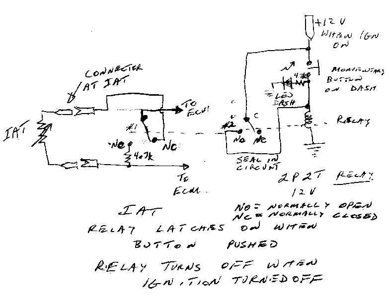
Regarding circuit in post 294 above I found DPDT automotive relays to be rare and PCB mount. Would use two SPDT relays such as the following: http://search.digikey.com/scripts/DkSearch/dksus.dll?Detail&name=Z2247-ND Both coils would be wired in parallel and consume about 120 mA each. Anyone keen enough to build it?
-
How about using a relay that keeps the IAT in the circuit by default when starting and then a momentary push button that latches the relay on and switches in the resistor of say 4.7 K. or so?Relay only de-energizes when ignition is turned off.
-
The infamous 216 VP44 death code only indicates "maximum timing can not be attained" which is just a TRUE or FALSE status rather than an error value (12 bit or whatever). I think that tells you it can not report timing via CAN-BUS although the VP44 itself measures it for internal use. I believe it has more to do with processing capability and CAN-BUS speed back in 1996 in such a hostile environment in a small space when this was designed.
-
I have seen a timing device for diesels using a piezoelectric pickup clamped to No 1 cylinder injection line and set to trigger a strobe light to light up a chalk mark for TDC on the damper. http://www.ferretinstruments.com/Ferret/765/765.html $259 is a little pricey since strobe is extra. Apparently a guitar pickup is piezo electric if one looks at the Wikipedia writeup. Failing that one, could use an oscilloscope with delayed sweep. Channel 1 probe on the vibration damper pickup for tach and sweep trigger on piezo pickup on no 1 inj line. One would have to measure exact number of degrees that tach pickup is off TDC and do some arithmetic. I am not talking first hand, as I have only been thinking of this when running into the problem myself on my 97. I bought the dial guage setup instead due to difficulty in finding suitable piezo device that would not be trial and error.
-
I hate to beat on this again but have a read of this. Applies to Timbo APPS as well but key is to measure voltage at APPS rather than PCM and then back off one turn. Not following this procedure results in failure of achieving "ON IDLE" state (never!)plus other problems. http://www.dieselram.com/showthread.php?t=198780 May have oldest post at bottom of thread so beware of that.

