


marked23
Unpaid Member
-
Joined
-
Last visited
Everything posted by marked23
-
Back in 2017, my 2001 2500 died in the driveway. I had just repositioned it so that I could load it up for a trip to the dump. An hour later, it wouldn't start. It would turn over, but not run. A friend brought a winch over, and we dragged the truck over to the side of the driveway. Five years later, it's still sitting there. It starts now, or it did in 2020, last time I tried. But I only get two positions on the throttle. Idle, and high-idle. (I think that indicates a toasted PSG5) If you look in my post history, you can see a few threads I made regarding my attempts to get it running again. Long story short, I drive a different truck now. But this one is still here, complicating my driveway. I wish I was still inspired to get it working.
-
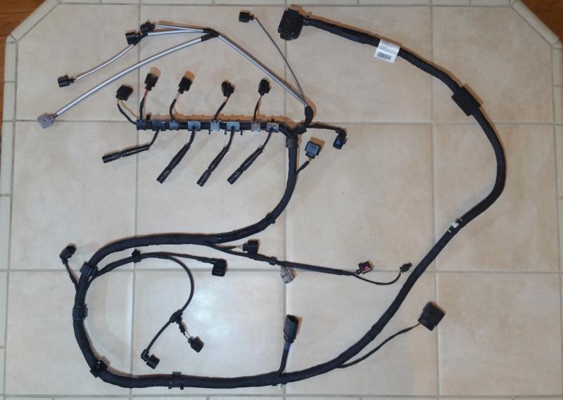
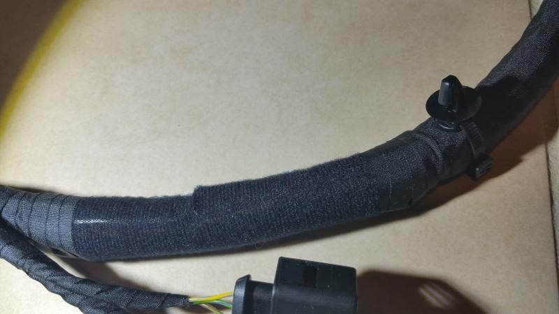
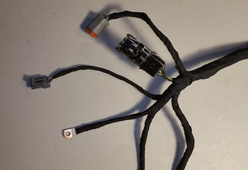
I need to replace the engine harness in my TDI. I just thought I'd share some pictures: The reason I have to replace it is because there are a couple poorly protected areas of the harness where the wire jackets suffer vibration damage. This is one of those spots. The harness is wrapped with harness tape everywhere, except for here [below]. For this section, they stopped wrapping with tape, and substituted with this semi-translucent black fabric that kinda looks like really thin and very fine-pitch velcro. This section of wire is prone to chafing as it wraps around the oil-filter housing. In my amateur opinion, it makes no sense to "protect" this section by removing the protective tape and replacing it with this thin cloth. Until I saw this, I was going to add an extra layer of tape to protect it. But now, not knowing why they did this, I'm stuck wondering if that would make it worse. There's also this one additional section that has the same treatment. No Idea why.
-
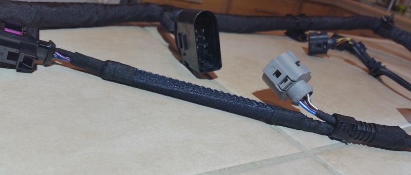
I'm using Tesa 51036 tape. http://www.tesatape.com/industry/tesa-51036.html I bought three rolls on amazon. I only used one roll to do all that wrapping. I have no prior experience with harness wrapping, but I found this stuff was really easy to work with. It's not very sticky... just sticky enough. If you accidentally stick it to itself, you can separate it without fuss. If you need to back off a few wraps and then continue, it seems to re-apply confidently. It's a tough cloth with a texture that feels like you could use it as armor.
-
Got it. "Short grounds are good." That makes sense. Thank you.
-
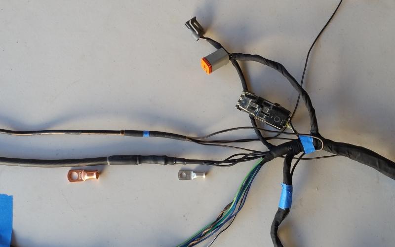
Ok... I unwrapped my freshly-wrapped harness to see how I could incorporate the W-T mod. This is my new ground wire sitting next to the stock ground wire. I tried to line them up so I compare the splice locations. Do I have enough length to the right-side of my splice, so that I can use the smaller connector? Or should I maybe use the larger connector and go all-the-way to the driver-side battery?
-
Tons of good reading from @W-T threads. Thanks for pointing those out. Now I have to reconsider my new ground wire.
-
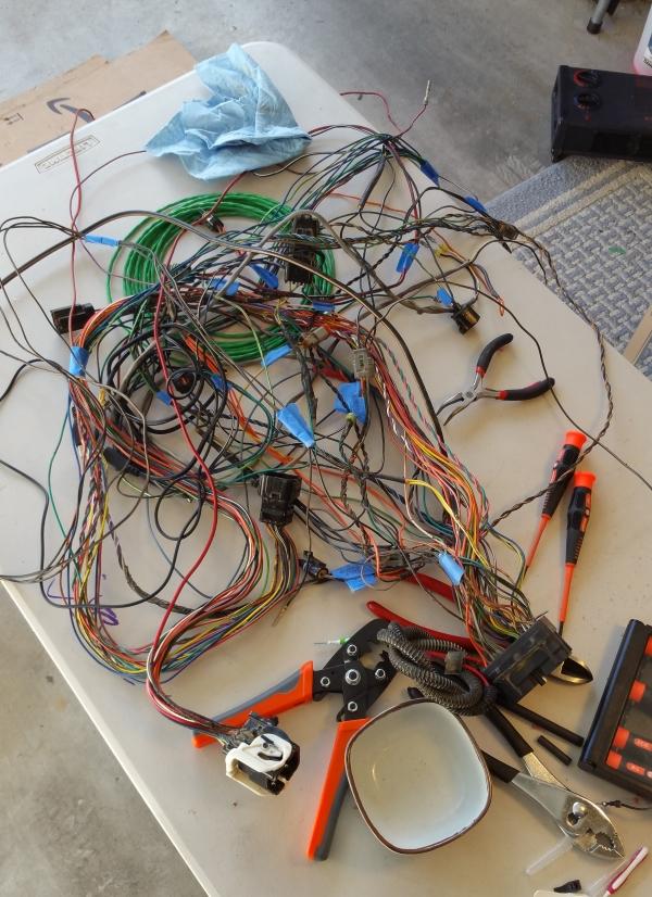
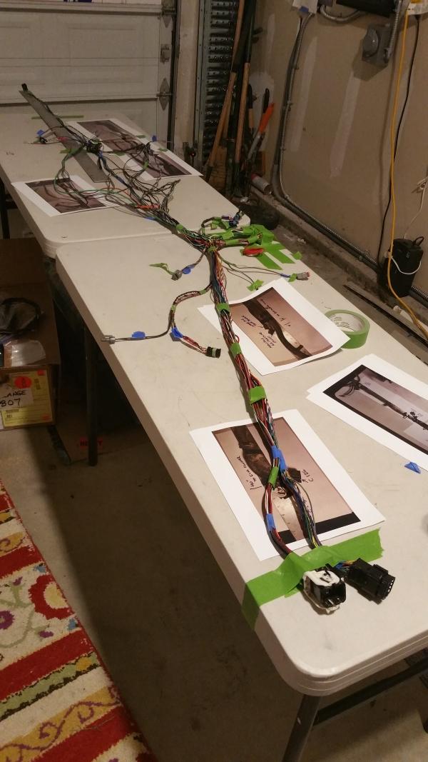
I've been ignoring this project for a few months, but I recently made some progress. So I'll share some pictures. If you ever have a hankering to rebuild an engine harness, this is your future: After several failed attempts to untangle that mess, I kicked the Camry out of the garage and set up some tables. I finally got a chance to re-wrap the harness this weekend. The coiled wire is the "computer" ground that connects to the passenger-side battery. I will cut it to length and crimp-on the end after the harness is installed. This entire ground-wire node was rebuilt from scratch using new wire and contacts. The VP44 connector shell is brand-new. I replaced the entire DATA (+) and DATA(-) shielded wire, that goes from this connector to the ECU. I replaced the contact on the #5 FUEL SHUT-OFF pin to repair the wire I damaged while troubleshooting. And the #6 GROUND, was replaced as part of the ground wire I mentioned above. I replaced the shell on the C126 connector. I wanted to do the same for the C125 connector but I was not able to find that shell. You might notice that the alternator-to-battery wire is no longer integrated into the same wrap. In an earlier project, I replaced all the battery wires. So when I took apart the harness, I removed the already abandoned B+ wire. I wanted to replace that red wire on the ECU connector, but I wasn't able to remove the pin from the shell without damaging the shell. So I'll just put that wire back together when I install the harness.
-
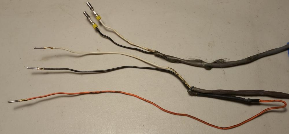
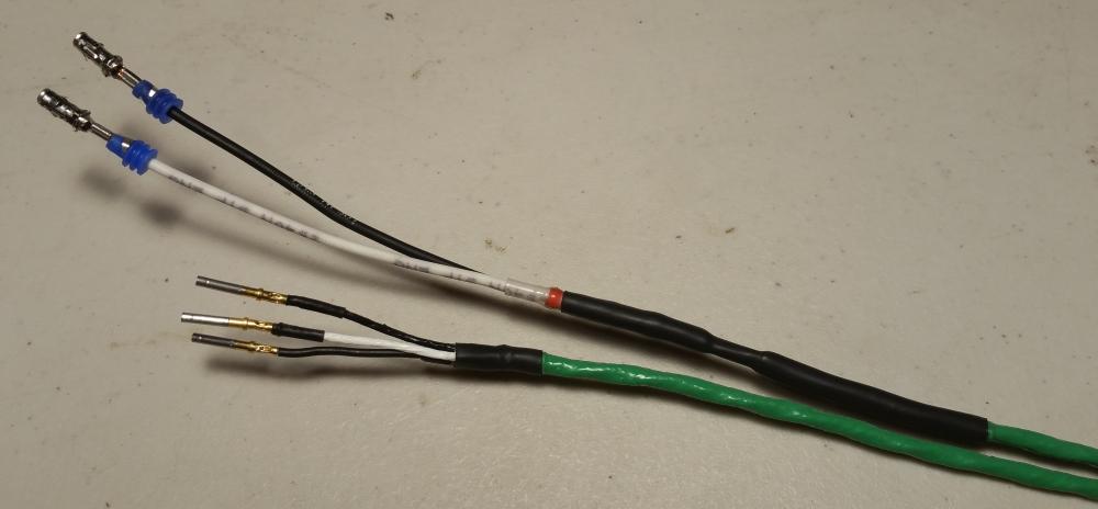
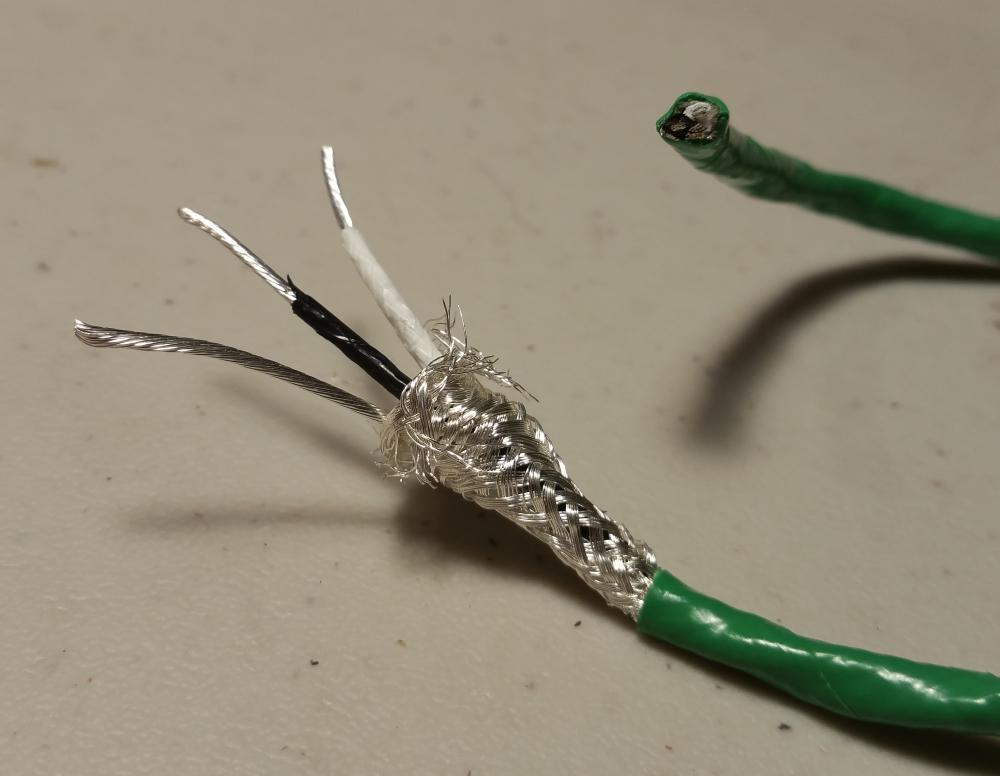
I'm replacing this wire: The wire is a shielded twisted-pair with a drain (SAE J1939/11). The wire seen here is the stock wire. It's comically unkempt. Note that the orange wire is about five inches too long, so that it must be doubled-back to make it the proper length. Also, the shielding is missing from the first six inches, and the last four inches. Neither of these is a problem from a functionality standpoint. I mean, it probably doesn't hurt anything. It's just sloppy. That loose twist of shielding provides no benefit, so why did they leave it loose like that? This is what I made to replace it. All new wire and connectors. It was hard to find a short length of J1939 wire. I found a few sources that were happy to sell me a 250ft spool, but I wasn't happy enough to buy it. I found a guy on ebay selling teflon/silver shielded twisted pair. $35 bought me 25ft. I wasn't trying to get silver. In fact, I wouldn't have bought it if I had realized that this is what it was. However, this is remarkable wire, so I'm going to give it a try. It's temperature rated to 200ºC. I don't know if it's oil rated.
-
@GSP7 I've chewed up my existing connector doing a bunch of tests to diagnose my VP44. I cut the Pin-5 wire too. So I got this to repair the damage I did. I'll replace all the contacts, while I'm at it.
-
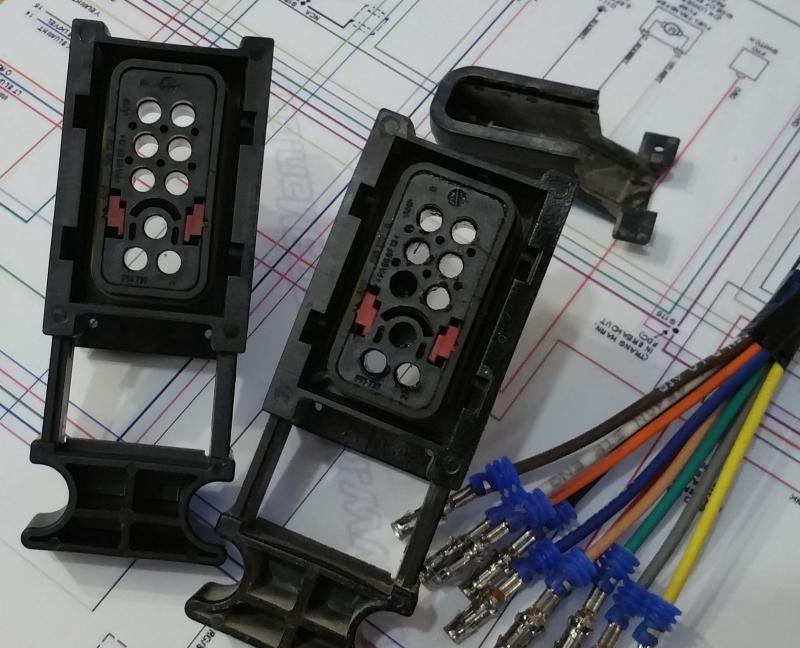
I found a source for VP44 connectors, and pigtails. http://americadiesel.us/ $13.20 for the connector shell $2.20 for each pigtail (I ordered 10, to allow for a few mistakes) $57 shipping My total was $92. Even with International Priority FedEx fees, that's still cheaper than other sources. It's a genuine AMP 965734, new. Our stock connector has two holes blocked. This one has all nine holes open, so I'll have to plug two. It did not come with the wire-cover back-plate. I ordered 10 pigtails. I was expecting them to be all one color, but I was happy to see that they randomized the colors for me. They aren't the factory colors/stripes, but any color is better than all-the-same.
-
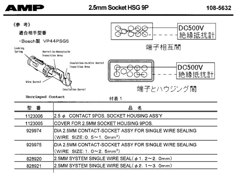
I found some AMP documents that show the terminal and part numbers. I pieced together the relevant bits. The 929974-x is for 17ga to 20ga wire. The 929975-x is for 13ga to 17ga wire. The heavier gauge is used for power +/- (pins 6 + 7). The rest are all the lighter gauge. I kind-of expect that the stock part was -3, but you'll never find any to buy. -8 seems to be the only gold variant that is available. -1 CuNiSi pre tin -2 CuNiSi silver plated -3 CuNiSi gold plated -4 CuFe2 pre tin -5 CuFe2 silver plated -6 CuFe2 gold plated -7 CuNiSi silver plated -8 CuNiSi gold plated <<< Choose this one. As seen here: Master Electronics 929974-8 Master Electronics 929975-8
-
@Bobalos, Is that tool used from the front, also? I tried to make one to extract the pins in that kind of connector. I couldn't figure it out. I'm looking for a source of the terminals for the VP44. I found some that have pigtails, but I want to do my own crimps, to avoid butt connectors. Those look close, but they don't have the big stop-flange at the back.
-
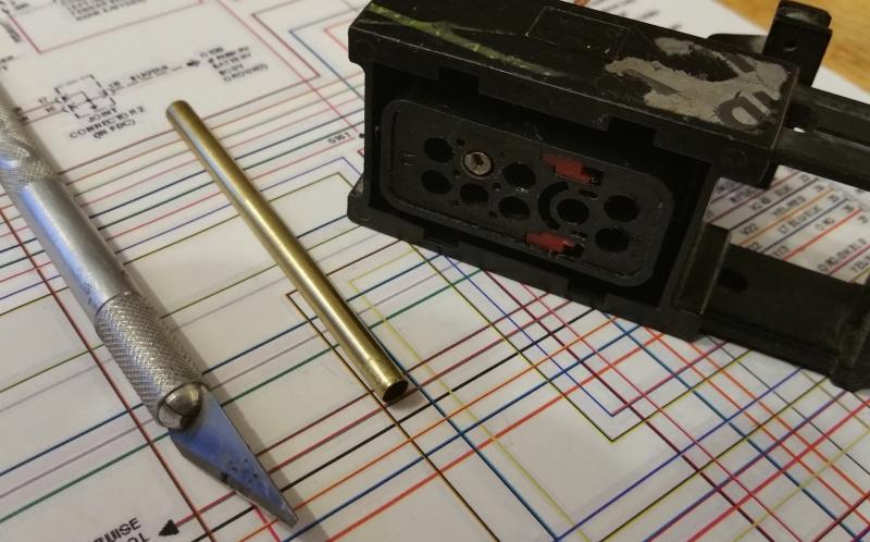
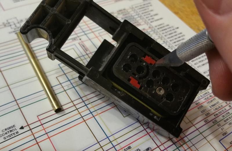
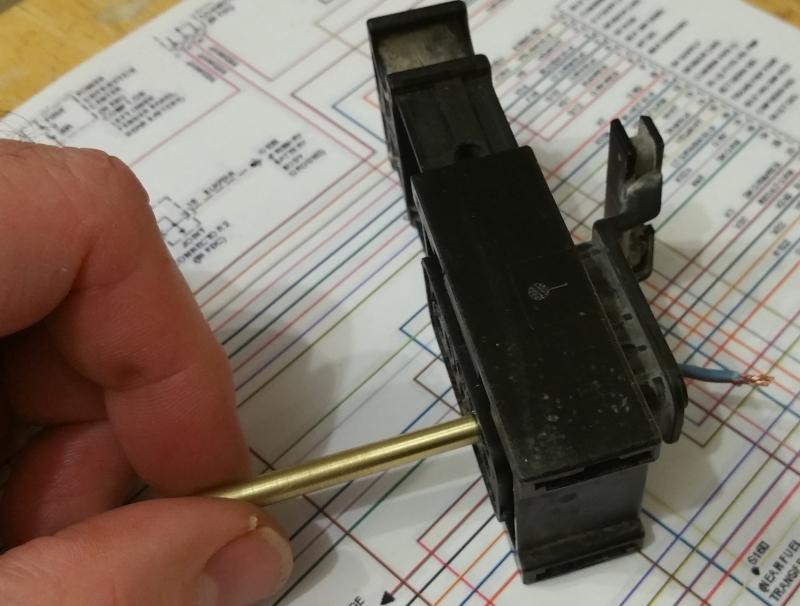
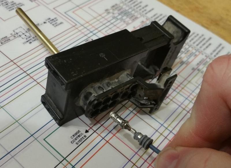
Maybe you've followed the VP44 diagnostics instructions over at blue chip... there's a point where one of the steps involves cutting the wire for pin 5. If you really need to do that experiment, don't cut your wire. Pull the terminal. I made a tool to extract terminals from a VP44 connector. It's just a bit of brass tubing. I put it in a drill and sanded it down until it was small enough to fit into the front of the connector. You need to move the little red tabs. This releases the lock that holds the terminals. But it's not the only lock. Insert the brass tube over the front of the terminal. It should go in about 1/4" or so. The tube will cover the barbs in the terminal... releasing the second lock. Then pull out the terminal. . Good times.
-
I wasn't really meaning to endorse those diagnostics instructions. I was just using that as an excuse to talk about one of the reasons you might want to extract pins from a VP44 connector. Nevertheless, here it is: https://www.bluechipdiesel.com/vp44_diagnostics.html I cut my pin-5 wire, and I wish I hadn't. It didn't do me any good. So knowing how to extract a pin might save somebody some grief.
-
Maybe you've followed the VP44 diagnostics instructions over at blue chip... there's a point where one of the steps involves cutting the wire for pin 5. If you really need to do that experiment, don't cut your wire. Pull the terminal. I made a tool to extract terminals from a VP44 connector. It's just a bit of brass tubing. I put it in a drill and sanded it down until it was small enough to fit into the front of the connector. You need to move the little red tabs. This releases the lock that holds the terminals. But it's not the only lock. Insert the brass tube over the front of the terminal. It should go in about 1/4" or so. The tube will cover the barbs in the terminal... releasing the second lock. Then pull out the terminal. . Good times.
-
It's a 2001 2500 chassis truck. My wife's brother is the original owner. The dealer moved the lift pump from the engine bay, into the tank. That's the only thing I know of that isn't 'factory'.
-
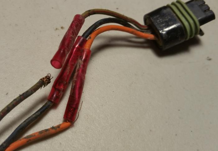
I know the previous owner didn't do this. He's the kind of guy that would buy a $300 crimper to do one crimp. So that means it came this way from the factory, or the dealer did this. My guess is that the dealer damaged the connector while removing the stock lift pump. This is the connector for the manifold air pressure sensor. Does anyone have an idea what kind of problem this would cause? I mean, if the truck runs, but doesn't have this sensor data, what would the truck do?
-
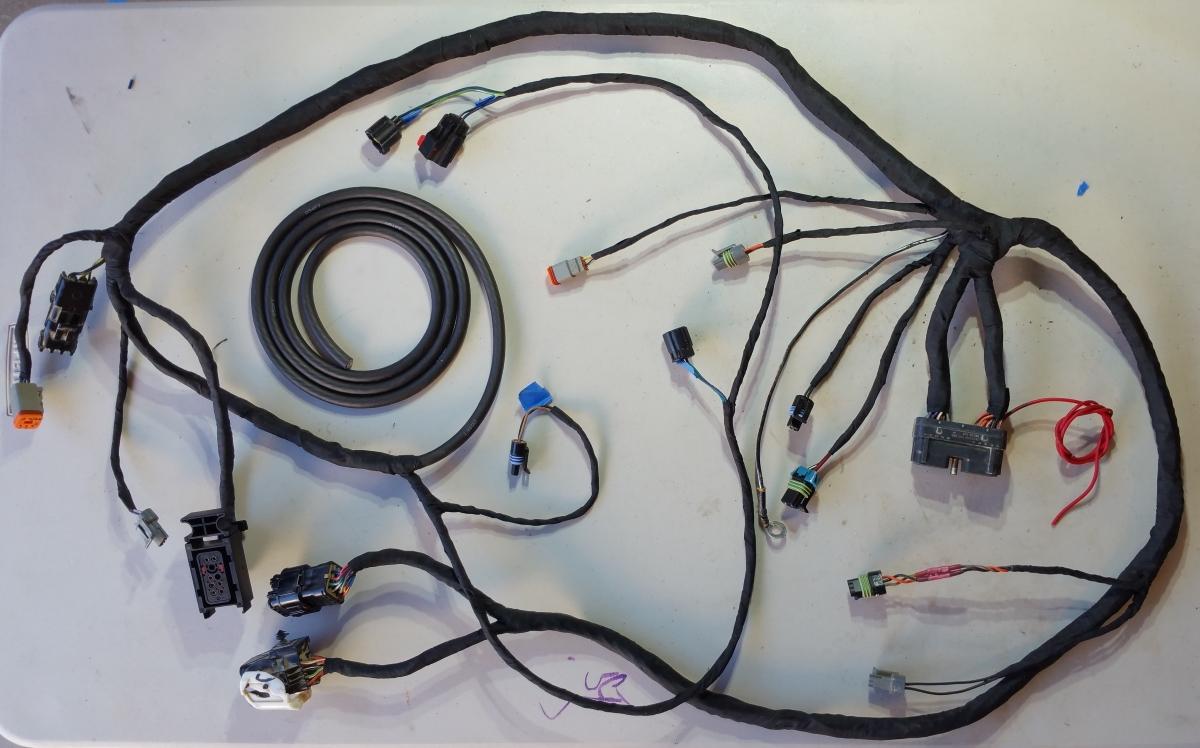
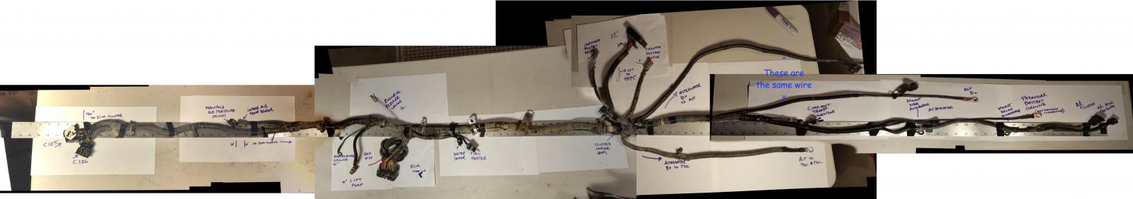
I'm going to unwrap and repair my engine wire harness. I figured that I should document what it is, so that I can put it back together when I'm done. This is an image I stitched together after taking about 20 separate pictures. Full_Stitch_6_5600x1000.zip
-
I contacted Cummins to see about a replacement ECM. They have them for $2700. The 3946242RX part number also goes by ENCORE CM551A. But then I also see a 3942860RX (CM550) that also claims to work with a VP44 for $1500. And also a 3944124RX for $1300. But these other two, I have no compatibility info on. I love how the overnight shipping for a 5 lb. part is $250.
-
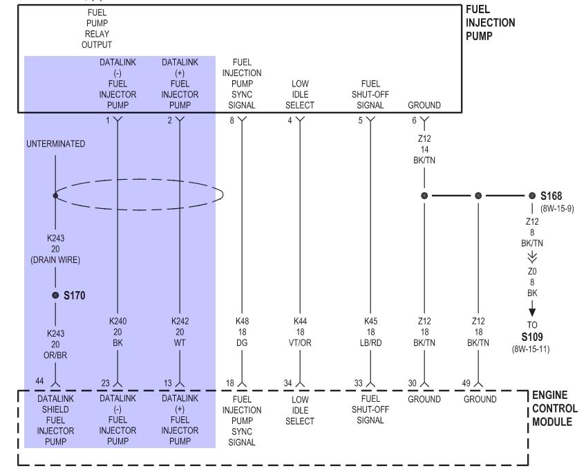
I've done the P1689 troubleshooting steps. I made it to the end of step #8. According to the steps, that means my ECM is bad. In keeping with the idea that "it's probably not the ECM," I've been trying to double-check the communication between the ECM and the VP44. I tried to put an oscilloscope on the VP44 today, to see if I could see the data. If I see the ECM's data, then it's the VP44 computer, not the ECM. I saw something that looked like PCM data, but I couldn't figure out how to set a stable trigger on it. I put channel #1 on the black & white wires (Pins 1 & 2), and put channel #2 on the green wire (Pin 8). Then I tried to trigger off of channel #2. If I tuned the trigger just right, it would hold-still for a couple seconds. I was expecting that the green wire (sync signal) would provide a perfect trigger. Does anyone know the correct scope setup to see this signal?
-
I had lots of corrosion on/in my battery wires. I replaced the terminals and the wires. Also replaced all the block & body grounds that connect directly to the batteries. The only other wire I replaced was the ground strap that goes from the body to the PCM case. I also installed a new alternator. This is my ac voltage with the new alternator. This doesn't look so good, huh? I'm not able to drive the truck, so keep in mind that this reading is on a cold engine. Still no improvement in throttle control, but I'm down to two symptoms. My compass thingy above the mirror says "CCD" I get code P1689
-
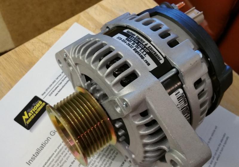
I decided to try some random changes to see if anything gets better or worse. I'm replacing all the battery cables. I got some of those Fastronix military terminals, some 2/0 wire, and big crimper. I'm replacing the alternator too.... which just arrived today.
-
I finally had the chance to do the AC voltage alternator test. This test was done without much of a warm-up. It's around 0.070v when quiet, but 0.105v when loaded (charging?). Also there's a 0.500v spike at the transition, when the load kicks-in. I don't have a scope, would like to see what that looks like. However, I can completely disconnect the alternator and still have this same accelerator pedal behavior. Interestingly, When I monitor the throttle position on ODB2, I see the throttle move smoothly. Whatever computer that is reporting to ODB2, that computer is getting a good signal from APPS. So I would guess that the APPS is probably working fine. But I still haven't ruled it out for sure. Thank you, -Mark
-
Does your wait to start light come on at key on? Yes. The whole key-on sequence seems normal except the lift-pump only running for 1/2 second. Then I bump the starter, and the lift-pump will run (maybe, maybe not) for another 15 seconds. If the lift-pump runs after the bump, the truck will start. Hot wiring the pump wont make the pump run? It makes the pump run, but doing that won't make the truck start. Is the engine turning over and just not starting or not turning over with the starter? It turns over great. It just doesn't start. Actually... it started twice today. It idled for about 20 seconds each time. I tried starting it about thirty times. Never had it running long enough to get a meter on the alternator. Thank you

