Varrieablefirstgen
Unpaid Member
-
Joined
-
Last visited
Everything posted by Varrieablefirstgen
-
Varrieablefirstgen replied to Varrieablefirstgen's topic in 2nd Generation Dodge Reliability / PerformanceOk thanks ive been pretty busy lately but when i get some time ill give it a shot!
-
Varrieablefirstgen replied to Varrieablefirstgen's topic in 2nd Generation Dodge Reliability / PerformanceInteresting if that is the case how would i go about to fix this issue or atleast diagnose/troubleshoot?
-
Varrieablefirstgen replied to Varrieablefirstgen's topic in 2nd Generation Dodge Reliability / Performancei wouldn't think so but i have no idea honestly i have the "turbo reset code" and it positions the veins where they should be then when i upload the main code the veins will cycle the way they should be IE if theres over 10 psi of boost the veins will open the pot switch will work correctly with the lcd screen 25cm is opened all the way and 3 is closed maybe the code is getting thrown off since the tps isnt hooked up ill try editing that out just to see what happens.
-
Varrieablefirstgen replied to Varrieablefirstgen's topic in 2nd Generation Dodge Reliability / PerformanceWhen it comes to code i really dont know what im doing ive done a little research on it but that only gets me so far. The code i have is from the building a standalone controller on this fourm, but the tests i have done the turbo speed sensor is not hooked up idk if that will affect it. All i know i test fitted the controller on the truck and the pot sensor works good and the cm^2 numerals on the lcd screen are correct to the vein position. Do you know of a video or source online that i can use to troubleshoot this ?
-
Varrieablefirstgen replied to Varrieablefirstgen's topic in 2nd Generation Dodge Reliability / PerformanceHey would you know why my EB isnt working correctly? I checked the values in the code and they are set to 900, 1000 which is right for 3cm but when i engage it it goes to 25cm just to try it i changed the values to 40, 140 and it did not make a difference? Any help would be appreciated everything else seems to be working as it should.
-
Varrieablefirstgen replied to Varrieablefirstgen's topic in 2nd Generation Dodge Reliability / PerformanceOk I wasn't sure if the 13.5 to 14 volts from the alternator would be too much
-
Varrieablefirstgen replied to Varrieablefirstgen's topic in 2nd Generation Dodge Reliability / PerformanceAnother question I have is how did you regulate the voltage / current to the Arduino once it's installed in the truck?
-
Varrieablefirstgen replied to Varrieablefirstgen's topic in 2nd Generation Dodge Reliability / PerformanceOk sounds good!
-
Varrieablefirstgen replied to Varrieablefirstgen's topic in 2nd Generation Dodge Reliability / PerformanceIf you get around to it i would appreciate it! if not no big deal, im going to hook it up eventually but I gotta find the bracket first but I was wondering what are some ideas you have for mounting/containing the arduino and shields? And the LCD screen too?
-
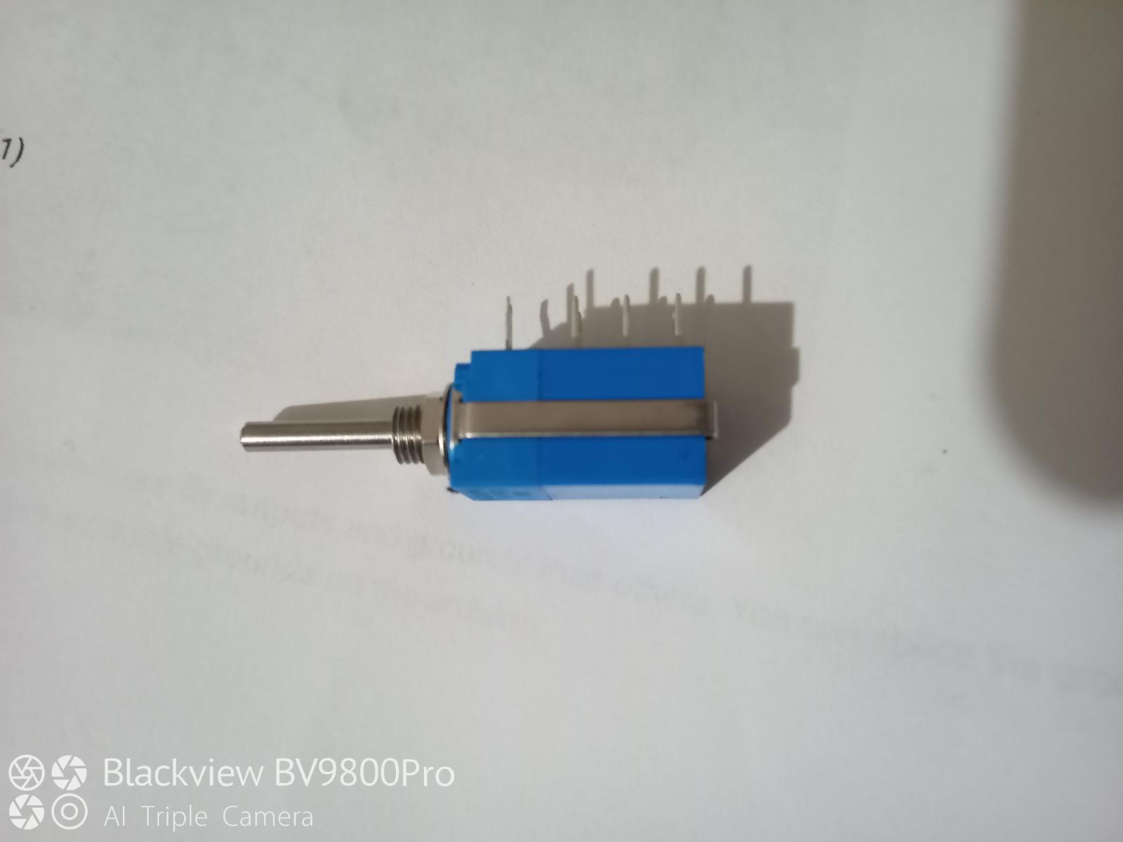
Varrieablefirstgen replied to Varrieablefirstgen's topic in 2nd Generation Dodge Reliability / PerformanceVarrieablefirstgen replied to Varrieablefirstgen's topic in 2nd Generation Dodge Reliability / Performanceok ill look into i i just was looking through an old thread (when you were first building the controller) and i seen where you helped someone out that had the same issue im having what i found is the can shield default cs pin was set to 9 you have to cut and solder to get pin 10 i just did that and it works! i do have to look into it more ill start with what you said because my lcd screen sill wont show anything and the pot sensor dosent seem to move the actuator gear very far but it does respond though!Varrieablefirstgen replied to Varrieablefirstgen's topic in 2nd Generation Dodge Reliability / PerformanceWhen i edit the code from Wire/Wire,h to Wire.h the code will verify and upload but nothing will happen ie. i cannot get the pot sensor to respond and i did check the wiring to be sure it was correct and the lcd screen will illuminate but not show anything do you think the can bus pin has anything to do with it? I know i had no response outta the reset code til i edited the can pin from 10 to 9 you had it in your notes that it could be pin 9 10 or 11 and 9 worked for me.Varrieablefirstgen replied to Varrieablefirstgen's topic in 2nd Generation Dodge Reliability / PerformanceArduino: 1.8.13 (Windows 7), Board: "Arduino Uno" A_HE351Mainfreq_TPS:47:10: fatal error: Wire/Wire.h: No such file or directory #include <Wire/Wire.h> ^~~~~~~~~~~~~ compilation terminated. exit status 1 Wire/Wire.h: No such file or directory This report would have more information with "Show verbose output during compilation" option enabled in File -> Preferences. When i had a friend of mine look at it he concluded that the Wire/Wire.h wasnt a library so he edited it to the Wire.h cause thats a pre installed library in the IDE program and the code would verify and upload from there but I think from editing that messed with the whole code but i know nothing about to to be sure i ordered some potentiometers and will use them to do a bench test of all the sensors but to my limited understanding i would think that the pot sensor would still work (the pot that will be installed in the truck) with out the other "sensor values present" i assume the Can Bus and Arduino Uno are fine because when i download the turbo reset code the actuator will respond to it. One thing worth mentioning is when i downloaded the turbo reset code i had to switch the can bus pin from pin 10 to pin 9 before it would work. Heres a quick reference of the turbo reset code that has to deal with the different pins #include <SPI.h> #include <can.h> #include <Wire.h> #define mode NORMAL // define CAN mode #define bitrate 250 // define CAN speed (bitrate) MCP CAN1 (10); //****This might be any pin 9 / 10 / 11 depending on the cnabus shield. Adjust to fit your needsVarrieablefirstgen replied to Varrieablefirstgen's topic in 2nd Generation Dodge Reliability / PerformanceHey so im having trouble with the code i could not get the 1.11 code to upload to my arduino i had a buddy of mine look at it and we concluded that the command (i know the terminology is wrong but i cant think of it right now) Wire/Wire.h was why i wouldnt verify/upload so we edited it to Wire.h Will this affect the operation of the system? I was able to try the actuator out with the turbo reset code it seems to work i have the actuator off the turbo right now but it will power up and rotate one way for a little bit then go the other way til you cut power im assuming that is correct and itll position itself correctly when the actuator is on the turbo. I have a feeling something isn't right for the main code 1.11 to run the turbo only because if i try and use the poteniometer the actuator wont respond same with the EB switch any insight would be appreciated i have checked my wiring again just to be sure and it is correct and i wont be able to know for sure til i get all my sensors and harness installed in the truck to try and do the real test im just trying to test as much as i can at the moment so when the time comes to install it everything will be ready to go! Also nothing show on the lcd displayVarrieablefirstgen replied to Varrieablefirstgen's topic in 2nd Generation Dodge Reliability / PerformanceNevermind i figured it out!Varrieablefirstgen replied to Varrieablefirstgen's topic in 2nd Generation Dodge Reliability / PerformanceHey so I'm having trouble now identifying what pot sensor I have and finding a wiring schematic for it I bought the one in the writeup on here it's a 9 pin pot sensor I understand how a three pin one works but I cannot find anything online about the nine pin and I'm unsure how to wire the ground return and ground up I understand the 5v sensor return and ground (like a3 wire pot) but the extra six pins with wiring the ground and ground return is confusing without no schematic.

 Varrieablefirstgen replied to Varrieablefirstgen's topic in 2nd Generation Dodge Reliability / PerformanceAwesome that makes sense I appreciate you taking the time to do the write upVarrieablefirstgen replied to Varrieablefirstgen's topic in 2nd Generation Dodge Reliability / PerformanceYea I can imagine it takes some skill and finesse to get it right The screenshot I put up on this form of the 9924 chip; I'm curious do you know the difference between the UAUBV+ UAUB+ UAUB? From my research it looks like they make a 9924 microchip and a bigger chip and that's what I have in the screenshot (the bigger version) if I can buy the 9924 in a bigger version I'll go that route but since I'm new in unsure about certain things and only have the internet for a reference and you guys so that's why I'm asking a lot of questions thanks for all the information thoughVarrieablefirstgen replied to Varrieablefirstgen's topic in 2nd Generation Dodge Reliability / PerformanceBecause I would solder the micro chip to the board and it would all look good but there would be 2 pins connected from the solder so I would try and pull the solder out and cause another set of pins to connect and it was a never ending cycle and from multiple times desoldering the chip to restart one of the ground pins broke off so I decided to go to a bigger 9924 chip it'll be easier for me to solderVarrieablefirstgen replied to Varrieablefirstgen's topic in 2nd Generation Dodge Reliability / PerformanceDoes it matter what 9924 chip I buy for running the turbo speed sensor? I had the microchip version and I'm not having any luck soldering it went through one already in the second one's about to break pins so I'm looking for a bigger version.
 Yea thanks for the info it was in that forumVarrieablefirstgen replied to Varrieablefirstgen's topic in 2nd Generation Dodge Reliability / PerformanceWhat watt rating 10k resistor would you recommend for tying in the 9924 chip?Does anyone know off the top of their head where to find the specs of the 351s plug I'm pretty sure it's gonna be a neg pos can high and can low I just need to know which ones are what before I wire it to my setup? thanksVarrieablefirstgen replied to Varrieablefirstgen's topic in 2nd Generation Dodge Reliability / PerformanceOk thanks for the info I'm slowly getting around to building this thing Your in ol pennsyltuckey too!Varrieablefirstgen replied to Varrieablefirstgen's topic in 2nd Generation Dodge Reliability / PerformanceSo being new to this I'm not 100% sure what the datasheet is if it is in this form in a write-up I've reviewed it I feel like I have a pretty good understanding of it the only question I have is the output of the 9924 chip #7 how I soldered the resistor and whatever IO8 is 8 know after that it goes to the pin in the Arduino\canbus shields hears a screen shot of what I'm talking about