

He351ve stand alone Arduino controller code for 2nd Gen Cummins
- Replies 746
- Views 141.1k
- Created
- Last Reply
Top Posters In This Topic
-
Me78569 370 posts
-
Vais01 69 posts
-
Cowboy 65 posts
-
Clarkwisely 40 posts


Most Popular Posts
-
Finally broke down and bought the t3 to wgmt flange of the 351ve. I should be getting this bolts up in the next couple weeks.
-
Hi again, i just wanted to update the thread, i finally got around to finishing my controller and got everything working with the 1.11 version of code, the main problem i was experiencing previously w
-
Yes, I created that video.


You can find the article for this build here
First I need to give credit where it is due and reconize Farm828 and other on CumminsForum in this Thread
Also I need to give major credit to Hakcenter from lilbb.com and his code and use of turbo RPM to calculate vane position.
I am currently working on getting my 351ve conrolled using a arduino uno and sparkfun canbus shield along with some other basic parts/sensors
Here are the list of parts that are used. you can void the code to use one or all of the sensors, but this list is for everything.
Parts: for controlling the he351 with boost and drive pressure
Arduino uno: https://www.sparkfun.com/products/11021$25
Canbus Shield: https://www.sparkfun.com/products/10039$40
Exhaust/boost sensor 0-100 psi: http://www.auberins.com/index.php?main_page=product_info&cPath=5_23&products_id=271x2 if you want to control the turbo on both exhaust and boost. $56 a piece
Potentiometer push pull 10k linear: http://www.ebay.com/itm/POTENTIOMETER-PUSH-PULL-SWITCH-POT-GUITAR-10K-LIN-SPLIT-SHAFT-LINEAR-V164L4-/271184505955?pt=LH_DefaultDomain_3&hash=item3f23db2c63 $5
Momentary on button switch: havent picked one up yet that I like. Currently using a computer button.
Wire: 16-20 gauge should be fine 100' should be enough
Connectors: I used DT06-12SA and DT06-12PA along with all hardware, ebay link
Parts: for controlling based on turbo shaft RPMS are a little more indepth. If you want to do that please visit lilbb.com and look over his setup and his parts list. He makes a shield that can control the turbo based on rpms.
in short you will need some resistors and a 9924 chip to count shaft speed.
Software:
You will need to download the Arduino program: http://arduino.cc/en/Main/Software
Download the Canbus library: https://www.dropbox.com/s/sldwefec5ybf04t/CANLibrarymaster.zip?dl=0 (thanks to Farm828)
download the LCD Library: https://www.dropbox.com/s/j4n35dhbl5wth8e/NewliquidCrystal.zip?dl=0
Basic Code downloaded here: https://www.dropbox.com/s/0wyvudbymjl0yg3/HE351VE_Control.ino?dl=0 (thanks to Farm828)
You can edit the code by voiding the sensors "//" you are using in the right section, defined.
My goals in short are: //updated 3/4/15
1. Boost to drive ratio of up to 2:1 until 30 psi is hit, then the veins will manage
2. Fast spool and near smokeless 400-450hp
3. When enabled, Potentionmeter that controls the veins manually until higher throttle input is sensed it will also try and manage DP is need be
4. Exhaust brake controlled by a momentary switch on the shifter select
5. Display sensor values on a simple serial LCD screen in cab.
I am currently running DFI 7x.009 injectors so your boostmaps in the below code may differ. You can copy and past the below into an arduino window and have it work.
current code for Boost/Drive controlled HE351ve If you choose to run in boost/drive controller mode you need to understand that it is VERY easy to over speed the turbo. I would highly recommend you use shaft speed.
Here is the code for using RPMS to control the turbo as said above you will need the added parts to count
Update - 3/4/15
Updated to include the changes for managing the EB apply, and the boostmap array issue. The above bench test well.
Update 2/23/15
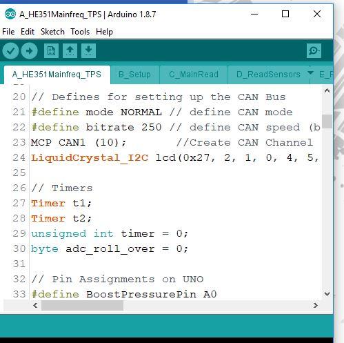
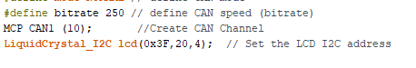
Thanks to cowboy I have a better method to print data to the serial lcd screen. I am using a 20x4 currently. you will need the i2c lcd library to make the above work. There is a message if the eb is applied or if the pot switch is active.
Update 3/4/15
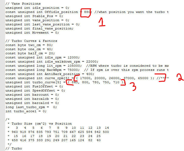
I have changed the way that I am trying to manage the DP while just driving. Below 30psi boost the veins are controlled by the boost map. This might have Drive to boost ratio of 2:1 ( haven't real world tested yet) however about 30psi boost I am switching over to a manage program that will try and keep Drive pressure at 50psi. The hope is, again not real world tested yet, that once 30 psi of boost is reached the manage loop will try and hold the veins at a position that keeps drive pressure at your defined max while the boost level catches up thus lowering the ratio when coming to the top of the turbos useable map. The DPmanage vein position limits are 650 lower and 970 top. 650 matches the 29.5 position for the boost map so there shouldn't be any jumping when switching between the two.
Update 3/6/15
I have removed the TPS % display on the lcd screen as I use my quad for that and I have added a Drive Pressure to Boost reference
"DtoB Ratio 1.5:1" etc
update 3/9/15
I have changed the Drive to boost ratio to actually work. I forgot to make it float and times by 1.00 to apply the decimal points needed.
Update 5/23/15
I have constrained the boost and drive pressure values to 0-100 values to not have negative values. I have also doubled the lcdupdate time to help make the lcd screen more readable.
update 5/26/15
i have updated the read sensor section to read at least twice and average the readings. I am reading exhaust sensor 5 times and averaging. I might increase the reads to get more accurate readings. Exhaust sensor jumps around somewhat, Not terrible but not great. I have also added a Boost reference so I can constrain the values I am looking at for the exhaust pressure averaging. In order for the exhaustpressure to be valid it has to be > boost pressure since it is technically impossible to have a drive pressure lower than boost pressure.
Update 5/27/15
I have worked through the reading of the exhaust and boost pressure reads to build an array of values and average the value to give a more accurate reading and to help keep rouge readings from giving bad reads.
Update 6/15/15
Thanks to Hakcenter at http://www.lilbb.com/ the code now has a timer in place to manage the sensor reads once every 400ms rather than reading them all at once like before. Code seems good, update is a little slower, but I am not sure if it will be an issue yet. I will be doing some testing and editing if needed. Hakcenter also has some code and shield to control the he351ve using the speed sensor.
Update 6/22/15
I have made some small changes to help improve the code. Biggest thing is the addition of 3 boost maps. You can select from performance / normal / mileage maps with the pot when you don't have the pot select switch active ( in my case I have a push pull and pot together on one switch so the manual control requires pulling the pot switch then adjusting position. 0-25 on the pot is performance 25-970 is normal and 970-1000 is mileage.
Update 6/23/15
After a couple days with the truck I have edited the boostmaps some. I have added a lcd indicator to show what boost map you are in. E= economy starts at 400 position or about 12 cm^2 D= drive mode starts at 235 or about 8 cm^2 and P=performance starts at 155 or about 6cm^2. P mode needs to be tuned more for my truck, but that pretty much ensures that there is always boost. Not the best to run as it pushes the turbo hard, but might prove helpful for emissions and so forth to keep smoke down.
All 3 modes stay within the boostmap until 30 psi then jump to drive manage to try and keep drive pressure at the defined limit ( 50 psi in my case).
Currently VERY happy with the turbo. I have some fuel issues that I am working on getting sorted, but I once the turbo lights it cleans up the smoke %100 all the way to 40+psi. Egts with the quad off don't top 1200*F and with the quad set all the way up got to 1500*f I can dial in the tune some to get that a little lower, but I am not worried.
6/24/15
I have adjusted the boostmap WAY up as the 235 ( 7-8cm) starting position was way to small. There is WAY less smoke and better spool starting around 300 ( 9-10cm) .
7/14/15
Thanks to HakCenter lilbb.com I have moved my code over to RPM based turbo calc. I have merged his lilbb 1.1 and my/cowboys boostmap code. The control of the turbo works better using RPMS. It is less jumpy, less smoke, no barking, more refined. Pretty happy so far. I have to clean some stuff up in the code, but over all working well.
7/15/15
Made some changes to the Posmanage section. The lilbb.com code doesn't take into account throttleposition ( 12v guy) so he was using turbo rpms to try and qualify idle state. While is does work good if you aren't watching throttle position it also means that you have to guess what is idle and what is not and sometimes there is times when you aren't truly at idle but the code thinks you are and you are left with the turbo open rather large, when it shouldn't be. again it works pretty good if you aren't watching throttle.
( little more detail on the "issue")
In order to qualify none idle turbo rpms would have come up to past curve[1]. This means that when starting from a stop the turbo position would be at about 14cm ( idle position) then it would slowly shrink down to the curve position. I was looking to have the turbo jump from idle state right to starting position as soon as you give it throttle.
Cummins/dodge has a idle position of around 14cm also, but as soon as you tap the throttle the turbo veins snap down to ~5cm then open up slowly to 9ish cm then on to the large positions as needed. This is to help "snap" the turbo speed up coming from a stop to clean smoke up.
Hench why I am trying to emulate that.
Update 7/25/15
Well a lot of changes are put into place. I did figure out that the LCD screen is taking a ton of time to run through, which is throwing off the RPM read each time the lcd updates ( 500 millis). Not a huge issue since we are averaging the turbo speed over 32 reads.
I have also added some top end stuff to prevent barking when letting off the throttle. I have also added a Position "bump" when over %45 throttle and %70 half cm at 45 and above and a full CM above %70 throttle. This will only occur when above the curve rpm [4].
What I found in my testing is
- With 100 hp injectors with no tuner I am able to keep the turbo position at about 12cm^2 to keep the turbo shaft speed in check below 130,000.
- With 100 hp injectors and canbus fueling (165hp total) Turbo position needs to be at 14cm^2 to prevent the shaft speed 130,000
- Wtih 100hp injectors, and canbus fuel and wiretap (100+65+115) Turbo position 18cm^2 to prevent the shaft speed 130,000.
that is how I am figuring everything out curve wise.
The top end controls now try to keep turbo rpms between 120k and 127k vane position will move more as rpm are further away from the goals.
Update 8/11/15
some changes to better comment everything. I have also went back to the top end controls setting a position rather than trying to increase and decrease to keep rpms at a certain speed. Unsure if I will keep that or not.
I have also cleaned up / sped up some of the lcd stuff. I removed the bar graph section. Even though it was nice to look at it was throwing off the turbo shaft speed reads. In the end it wasn't worth running. This allows me to print less to the lcd screen.
Update 8/20/15
I have adjusted the curves some. I have also added a new section to the TPS sense that will reduce the vane position if you are at low/mid/midhigh/high but low boost to help spool the turbo. This is to help with reducing smoke when going from cruise to high throttle.
IE: You can see that if tps_midlow is true ( between %25 and %45 tps) and bosot is below 5psi the housing will close by 40 which is roughly equal to one cm. If tps is midlow and boost is less than 10 then shrink housing by half cm.
you can see below that I move the shrink/opening more as tps goes up to go along with the amount of fuel.
Edited by Me78569