

Working through miss/studder issues - codes 0237 & 0230
- Replies 52
- Views 4k
- Created
- Last Reply
Top Posters In This Topic
-
timsch 23 posts
-
Tractorman 20 posts
-
Mopar1973Man 9 posts


Most Popular Posts
-
There is a single connector with two black wires that are connected to the positive post of the driver side battery. These wires supply power to the intake manifold heaters (grid heaters). Within a fe
-
You can just swap out another like fuse and another relay and go for a quick test drive. John
-
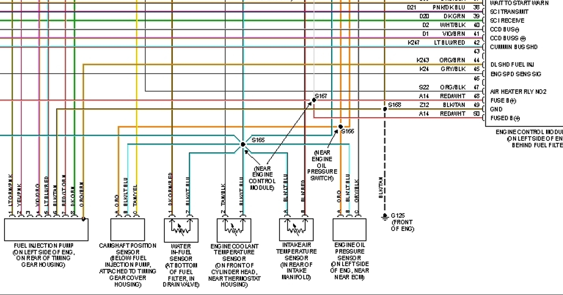
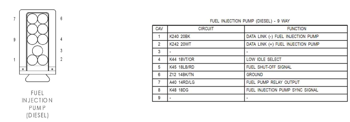
On the Dodge FSM it will list wire colors and gauge size.
I picked up a 2000 Ram 2500 with the Cummins a few months ago. The PO said that he'd replaced the fuel pump a couple of times, which I should have paid more attention to. Ran fine though for a few months. Recently I had a big miss, or shudder under heavy acceleration onto a highway but ran fine for the rest of the trip. It happened several more times on later trips, usually at gradual acceleration. No CEL at that time. I did get the 0237 code, so got a new MAP sensor hoping that would fix it, but it didn't. I cleaned all grounds and harness connectors. Since then, a few test drives have been OK, with no missing, but even though I cleared the codes, they come back.
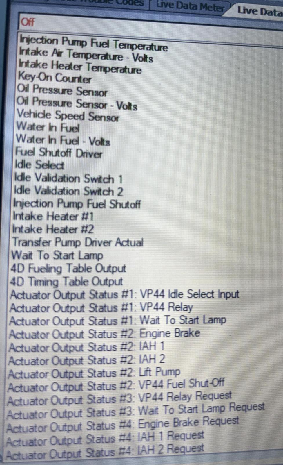
I have AutoEnginuity, so got the Chrysler enhancement package and found a few things. The MAP sensor checks out with 5.2V key on engine off. Test run yesterday, backing out of the driveway the voltage dropped to 4.93 briefly. Once going down the road, it stayed above 5V and responded seemingly correctly to acceleration. I suppose that the brief drop below 5V would be enough to throw a code. Let me know if otherwise. I haven't tried bending the diaphragm yet as described in a HOW TO DIAGNOSE VP44 FUEL SYSTEM ISSUES document.
Another thing I noticed was that the VP44 input voltage was dropping from 12.18V down to ~9V. Occasionally it would jump up to 13.5V, which is what I was measuring at the battery when it was running and the alternator was charging. 12.18V was what the battery read before starting. They were brief excursions either way, but it got progressively more frequent going down to 9V as my test drive went on. I can log and provide these charts.
The Banks tuner was unplugged during my testing, but was plugged in when I first started having the miss/shudder issue.
I thought I might be in limp mode, but I was getting boost pressures of 5-8 psi with just moderate acceleration on a test drive yesterday. Didn't feel too bad.