


Me78569
Unpaid Member
-
Joined
-
Last visited
Everything posted by Me78569
-
64/68/14 should get you there I would think I dunno if I would go with the 71, but I am not an expert @TFaoro @jlbayes ?
-
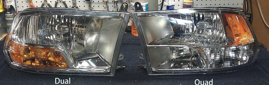
1.Disconnect and isolate the battery negative cable. 2.Remove the four plastic push-in fasteners (1) that secure the upper radiator seal to the grille support and both fender ledges. 3.Remove the two plastic push-pin rivets (2) that secure the upper radiator seal to the radiator. 4.Remove the upper radiator seal from the vehicle. NOTE: It is not necessary to remove the grille from the front of the vehicle to service the front lamp units. The illustration shows the grille removed only to assist in clearly identifying the locations of the front lamp unit mounting provisions. 5.Remove the screw (1) that secures the upper mounting tab of the front lamp unit (2) to the Front End Module (FEM) carrier (also known as the radiator closure) (4). 6.Using a socket with a magnetic insert or with a small piece of butyl tape inserted, reach down between the grille and the FEM carrier to access, remove and retrieve the screw (3) that secures the lower mounting tab of the front lamp unit. 7.Remove the fastener that secures the tab at the bottom of the access panel (2) to the front of the front wheel house splash shield (1). NOTE: The illustration shows the back of right front lamp unit and slide lock with the slide lock in the locked position. 8.Reach through the access opening (1) of the wheel house splash shield and lift the slide lock (3) upward far enough to disengage it from the lock post (2) integral to the back of the front lamp unit housing (4). 9.From the front of the vehicle, grasp the outboard edge of the front lamp unit firmly and pull it straight forward to disengage the ball stud (1) from the plastic grommet in the FEM carrier. 10.Pull the lamp away from the front of the vehicle far enough to access and disconnect the two wire harness connections from the park/turn signal bulb socket (4) and either the headlamp bulb (2) on vehicles with dual headlamps, or from the headlamp pigtail wire harness on vehicles with quad headlamps (not shown). 11.Remove the front lamp unit from the vehicle. View full Cummins article
-
1.Disconnect and isolate the battery negative cable. 2.Remove the four plastic push-in fasteners (1) that secure the upper radiator seal to the grille support and both fender ledges. 3.Remove the two plastic push-pin rivets (2) that secure the upper radiator seal to the radiator. 4.Remove the upper radiator seal from the vehicle. NOTE: It is not necessary to remove the grille from the front of the vehicle to service the front lamp units. The illustration shows the grille removed only to assist in clearly identifying the locations of the front lamp unit mounting provisions. 5.Remove the screw (1) that secures the upper mounting tab of the front lamp unit (2) to the Front End Module (FEM) carrier (also known as the radiator closure) (4). 6.Using a socket with a magnetic insert or with a small piece of butyl tape inserted, reach down between the grille and the FEM carrier to access, remove and retrieve the screw (3) that secures the lower mounting tab of the front lamp unit. 7.Remove the fastener that secures the tab at the bottom of the access panel (2) to the front of the front wheel house splash shield (1). NOTE: The illustration shows the back of right front lamp unit and slide lock with the slide lock in the locked position. 8.Reach through the access opening (1) of the wheel house splash shield and lift the slide lock (3) upward far enough to disengage it from the lock post (2) integral to the back of the front lamp unit housing (4). 9.From the front of the vehicle, grasp the outboard edge of the front lamp unit firmly and pull it straight forward to disengage the ball stud (1) from the plastic grommet in the FEM carrier. 10.Pull the lamp away from the front of the vehicle far enough to access and disconnect the two wire harness connections from the park/turn signal bulb socket (4) and either the headlamp bulb (2) on vehicles with dual headlamps, or from the headlamp pigtail wire harness on vehicles with quad headlamps (not shown). 11.Remove the front lamp unit from the vehicle.
-
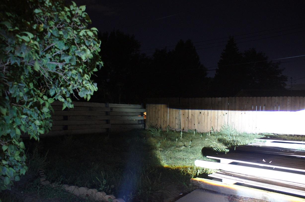
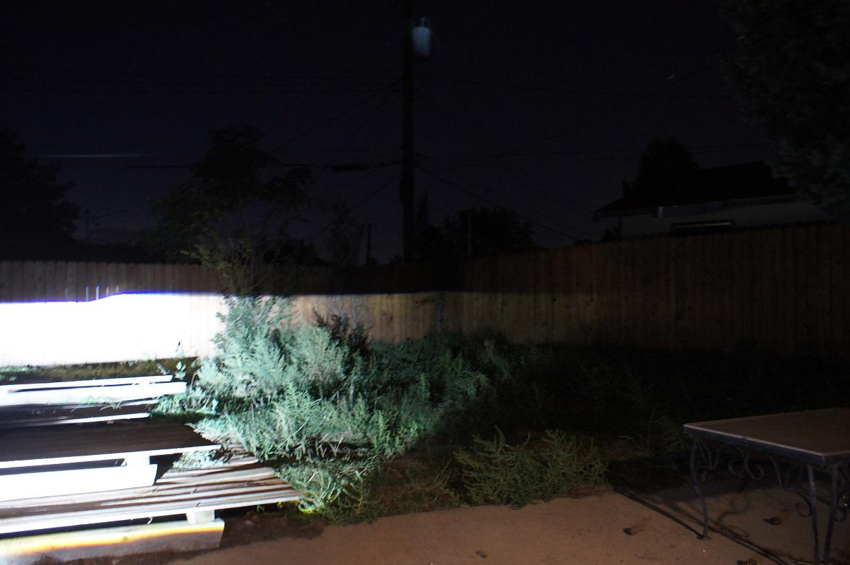
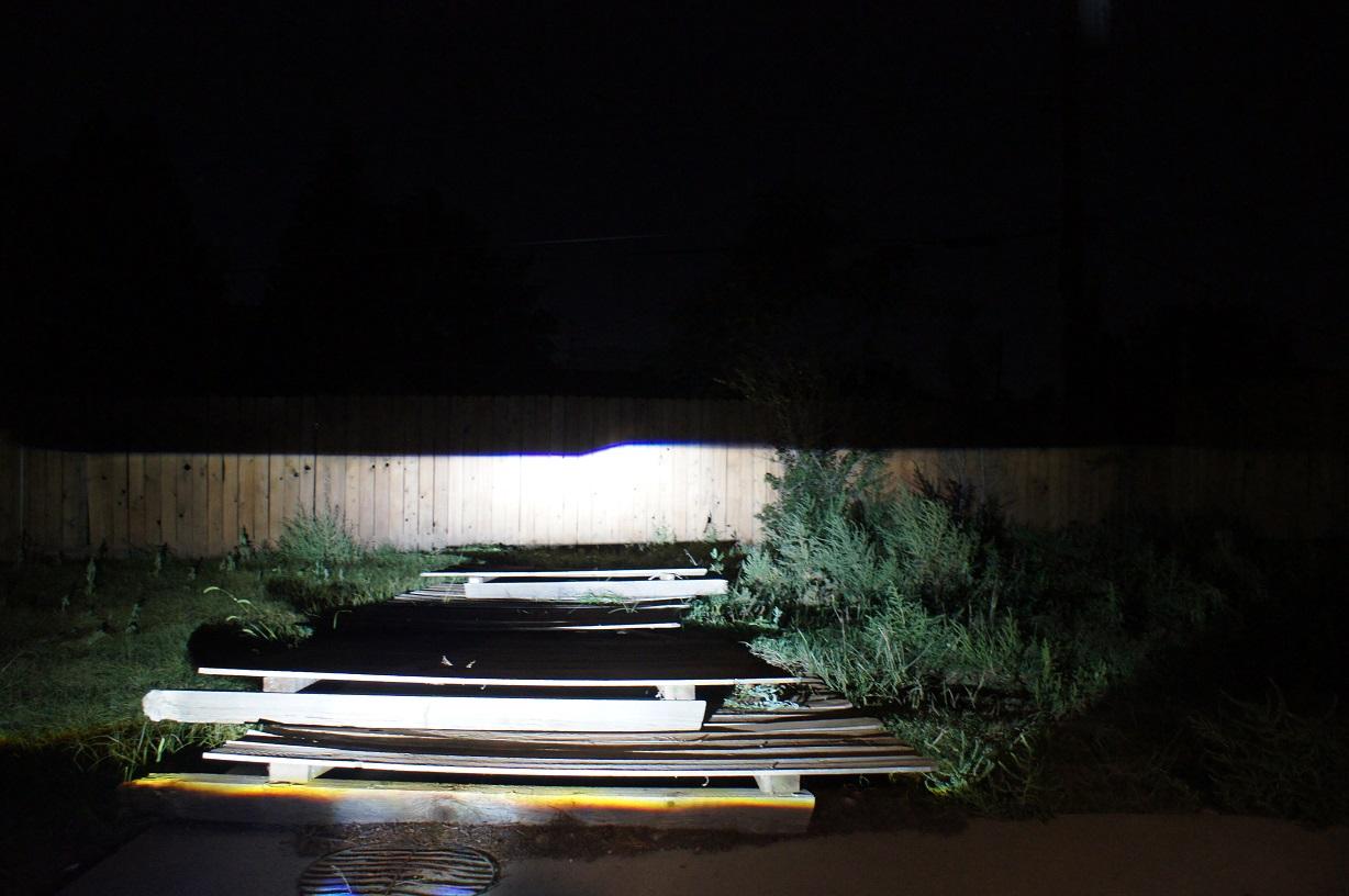
Morimoto M Bi-LED Projector Headlight Retro Fit Perks of LED vs HID retrofit No warmup time Less Electrical Draw 15,000 hour rated use AKA no burnt out bulbs Less wires No relays Simpler install plug and play with newer trucks ( no dash messages due to needing a relay setup) anti-flicker might be required. extremely bright hotspot ( on par with Mini D2S 4.0 ) this doesn't come without Con's but what doesn't have a con? less width on the output have to replace the unit if it fails too much foreground light in some application Price is higher on the MLED than comparible HID projector kits. Tools you'll need to do the installation Drill Flat blade screwdriver to pry with 1 3/8" inch hole saw or 1 1/2" saw ( I prefer the smaller to give a tighter fit) Wire wheel to remove old sealant, might not be needed 3/4 " drill bit or step drill bit. Oven cleaner to remove the chrome ** should you want that. Parts for the LED Headlight Retro Fit Spare headlight housings to work with ****this is highly recommended, but not a requirement. Having a spare set of headlight housings gives you the ability to take your time during the project. The spare headlight housings might also allow you to choose a headlight style you like to actually install in your truck. Keep in mind if you go with non-OEM headlight housings that you will want to make sure the aftermarket headlights housings are of decent quality. Headlight wiring Splitter, If you are using a Quad Beam housing and want to keep the halogen High beam you will need to split the high beam into the Morimoto LED controller. You will need a wiring adapter to go from the OEM headlight wiring into the twin 9006 plugs on the Morimoto control box. BI-LED: MORIMOTO M LED kit from a Vendor of your choosing. A roll of Butyl or similar to reseal your housings. Start by Removing your Stock Headlights Removing Housing Lens Next, you will need to bake your headlight housings to free up the sealant on the housings to get the lenses off. If you trust your oven choose 225*f -250*f for ~10-15 minutes. Making sure you check every few minutes to make sure you aren't melting your headlights and pissing off your wife You will be able to pull the lenses away from the headlight housing with a bit of work. Don't pry too much, ensure you work your way around the headlight housing popping the clips etc. Once you have one corner of the headlight lens free you can work from that point cutting the sealant as you go. Note: it might take a few times in the oven to get the headlight lens completely off the headlight housing. The hardest part will be this corner of the headlight lens as it is tucked in pretty well in the corner of the headlight housing. Work your way around the headlight housing on the top and bottom to free up any glue up to this point, then you will want to pull the headlight lens up and out as you cut the glue. Once you have the headlight lens free you will note a sub faceplate to cover up the empty housing. This Bezel sits in the empty housing and can be popped out easily. This is a good point to clean stuff up. If you are going to remove chrome AKA "Black Out" your headlights this is the point to do it. Oven cleaner will strip the chrome from the bezels and reflector. The Morimoto BI LED Projectors Here is what the BI-LED: MORIMOTO M LED projector kit will contain. Top to bottom 1. Bi LED Morimoto M LED Projector 2. Morimoto LED control Box 3. Silicon and securing nuts. 4. Shroud: you can choose the shroud you want, I decided to use Apollo 3 Black. It will need to be cut down to fit into the Quadlight. It will need just a little trimming to fit in the 2010-2012 housings. Modifying your Housing to fit the 35MM M LED D2S tail mount. Most Morimoto Projectors are mounted to the OEM headlight housing using a threaded Tail Shaft. This makes for a simple and straightforward install that allows for you to use the OEM alignment points. Use the 1 3/8" or 1 1/2" hole saw to cut through the OEM bulb mount. Take it slow so you keep it centered and true. Next prep your Morimoto projector for fitting. Put the silicone seal on the Tail Mount, note the silicone seal can be oriented with thicker and thinner sides. Put the tail of the projector into the housing. slide on the keyed alignment washer and then thread on the nut until tight. Flip your headlight housing around and take a peek at your lights. Center them and make it look right. Tighten the nut more until the projector is not easy to rotate. You will still need to level the projectors once they are installed into the truck. Now Test fit your Shroud into the housing. Note that the very top of the shroud needs to be cut down to prevent the shroud from being squished. Next you will need to drill a secondary hole for your power lead to run into the housing. There is a grommet provided to use. Use a step drill bit to put a 3/4" secondard hole into place. Route the M LED power wire through the new hole and fit the grommet so that the wire loom comes out the back of the housing. Tuck the wiring away to be hidden behind the covering bezel. test fit the lense to ensure everything is fitting well. DON'T seal your lense yet. You still need to install the housings into the truck and level the cutoff of the projector. I actually decided I wanted to keep the QuadBeam light setup so I bought another set of housings and went tthrough the process again. I used oven cleaner on the low beam reflector then painted it black. ensure you use paper towel or something to protect the high beam area. I also dont like the looks of shrouds so I installed them without them. I scratched the lens when I was sealing. I will have to buff it out. Next you need to mount the Morimoto M LED control box into the truck. I prefer to mount it to the back of the housing. Given the small size of the MLED control box it is easy to find a good place for it. Pictures showing of how the LED control box is mounted. the approx location is in the red area. I used a rivet to hold it in place. a nute and bolt would also work. Wiring Connect up your OEM headlight wiring to the Morimoto M LED control box. If you are using the Quad beam housings you will need a low beam splitter so the Halogen high beam still operates, but the M LED still gets the signal to flip down the high beam shield. You will also need to split the OEM plug into high and low beam as well. If you are using the single beam housings you will just need a OEM plug to 9006 splitter to split the single plug into a low and high beam 9006 harness. Here is a very basic wiring schematic for the setups. Quad Light harness Make your 9006 splits for the highbeam. You will need 2. The black oem plug is the high beam. You want to splice your 9006 plugs into the area near my thumb white/green is hot black is ground use heat shrink wrap on your splice soldier your wires finished harness. Here you can see the housings put together with %100 plug and play on OEM wiring. The Blue RTV on the side is covering the rivet that holds the control box inside the housing. Leveling your lights Now it is time to test your lights out and get them leveled. Find a Level spot with a flat wall ~25-50' away from the truck. The goal is to make your cut off's as level as possible. Here you can see poorly leveled cut off's Rotate your projectors until you have a nice level cutoff, MAKE SURE YOU MAKE A SMALL MARK to show the projector alightment you like just in case you bump it prior to tightening it down. Don't worry about the height yet as you will adjust that using the OEM housing adjustments. Once you are happy with your cutoff then tighten down the retaining nut on the tail of the projector mount until tight and the projector can no longer move. Once you are happy with the cutoff then it is time to seal up your housings using Butyl. Follow the directions on the Butyl to ensure a good seal. Reinstall the housings into your truck and now it is time to aim them. Output shots Stock Low (click to see uncompressed image) Stock High (click to see uncompressed image) Mled Low (click to see uncompressed image) Mled High (click to see uncompressed image) Front view of the truck View full Cummins article
-
Morimoto M Bi-LED Projector Headlight Retro Fit Perks of LED vs HID retrofit No warmup time Less Electrical Draw 15,000 hour rated use AKA no burnt out bulbs Less wires No relays Simpler install plug and play with newer trucks ( no dash messages due to needing a relay setup) anti-flicker might be required. extremely bright hotspot ( on par with Mini D2S 4.0 ) this doesn't come without Con's but what doesn't have a con? less width on the output have to replace the unit if it fails too much foreground light in some application Price is higher on the MLED than comparible HID projector kits. Tools you'll need to do the installation Drill Flat blade screwdriver to pry with 1 3/8" inch hole saw or 1 1/2" saw ( I prefer the smaller to give a tighter fit) Wire wheel to remove old sealant, might not be needed 3/4 " drill bit or step drill bit. Oven cleaner to remove the chrome ** should you want that. Parts for the LED Headlight Retro Fit Spare headlight housings to work with ****this is highly recommended, but not a requirement. Having a spare set of headlight housings gives you the ability to take your time during the project. The spare headlight housings might also allow you to choose a headlight style you like to actually install in your truck. Keep in mind if you go with non-OEM headlight housings that you will want to make sure the aftermarket headlights housings are of decent quality. Headlight wiring Splitter, If you are using a Quad Beam housing and want to keep the halogen High beam you will need to split the high beam into the Morimoto LED controller. You will need a wiring adapter to go from the OEM headlight wiring into the twin 9006 plugs on the Morimoto control box. BI-LED: MORIMOTO M LED kit from a Vendor of your choosing. A roll of Butyl or similar to reseal your housings. Start by Removing your Stock Headlights Removing Housing Lens Next, you will need to bake your headlight housings to free up the sealant on the housings to get the lenses off. If you trust your oven choose 225*f -250*f for ~10-15 minutes. Making sure you check every few minutes to make sure you aren't melting your headlights and pissing off your wife You will be able to pull the lenses away from the headlight housing with a bit of work. Don't pry too much, ensure you work your way around the headlight housing popping the clips etc. Once you have one corner of the headlight lens free you can work from that point cutting the sealant as you go. Note: it might take a few times in the oven to get the headlight lens completely off the headlight housing. The hardest part will be this corner of the headlight lens as it is tucked in pretty well in the corner of the headlight housing. Work your way around the headlight housing on the top and bottom to free up any glue up to this point, then you will want to pull the headlight lens up and out as you cut the glue. Once you have the headlight lens free you will note a sub faceplate to cover up the empty housing. This Bezel sits in the empty housing and can be popped out easily. This is a good point to clean stuff up. If you are going to remove chrome AKA "Black Out" your headlights this is the point to do it. Oven cleaner will strip the chrome from the bezels and reflector. The Morimoto BI LED Projectors Here is what the BI-LED: MORIMOTO M LED projector kit will contain. Top to bottom 1. Bi LED Morimoto M LED Projector 2. Morimoto LED control Box 3. Silicon and securing nuts. 4. Shroud: you can choose the shroud you want, I decided to use Apollo 3 Black. It will need to be cut down to fit into the Quadlight. It will need just a little trimming to fit in the 2010-2012 housings. Modifying your Housing to fit the 35MM M LED D2S tail mount. Most Morimoto Projectors are mounted to the OEM headlight housing using a threaded Tail Shaft. This makes for a simple and straightforward install that allows for you to use the OEM alignment points. Use the 1 3/8" or 1 1/2" hole saw to cut through the OEM bulb mount. Take it slow so you keep it centered and true. Next prep your Morimoto projector for fitting. Put the silicone seal on the Tail Mount, note the silicone seal can be oriented with thicker and thinner sides. Put the tail of the projector into the housing. slide on the keyed alignment washer and then thread on the nut until tight. Flip your headlight housing around and take a peek at your lights. Center them and make it look right. Tighten the nut more until the projector is not easy to rotate. You will still need to level the projectors once they are installed into the truck. Now Test fit your Shroud into the housing. Note that the very top of the shroud needs to be cut down to prevent the shroud from being squished. Next you will need to drill a secondary hole for your power lead to run into the housing. There is a grommet provided to use. Use a step drill bit to put a 3/4" secondard hole into place. Route the M LED power wire through the new hole and fit the grommet so that the wire loom comes out the back of the housing. Tuck the wiring away to be hidden behind the covering bezel. test fit the lense to ensure everything is fitting well. DON'T seal your lense yet. You still need to install the housings into the truck and level the cutoff of the projector. I actually decided I wanted to keep the QuadBeam light setup so I bought another set of housings and went tthrough the process again. I used oven cleaner on the low beam reflector then painted it black. ensure you use paper towel or something to protect the high beam area. I also dont like the looks of shrouds so I installed them without them. I scratched the lens when I was sealing. I will have to buff it out. Next you need to mount the Morimoto M LED control box into the truck. I prefer to mount it to the back of the housing. Given the small size of the MLED control box it is easy to find a good place for it. Pictures showing of how the LED control box is mounted. the approx location is in the red area. I used a rivet to hold it in place. a nute and bolt would also work. Wiring Connect up your OEM headlight wiring to the Morimoto M LED control box. If you are using the Quad beam housings you will need a low beam splitter so the Halogen high beam still operates, but the M LED still gets the signal to flip down the high beam shield. You will also need to split the OEM plug into high and low beam as well. If you are using the single beam housings you will just need a OEM plug to 9006 splitter to split the single plug into a low and high beam 9006 harness. Here is a very basic wiring schematic for the setups. Quad Light harness Make your 9006 splits for the highbeam. You will need 2. The black oem plug is the high beam. You want to splice your 9006 plugs into the area near my thumb white/green is hot black is ground use heat shrink wrap on your splice soldier your wires finished harness. Here you can see the housings put together with %100 plug and play on OEM wiring. The Blue RTV on the side is covering the rivet that holds the control box inside the housing. Leveling your lights Now it is time to test your lights out and get them leveled. Find a Level spot with a flat wall ~25-50' away from the truck. The goal is to make your cut off's as level as possible. Here you can see poorly leveled cut off's Rotate your projectors until you have a nice level cutoff, MAKE SURE YOU MAKE A SMALL MARK to show the projector alightment you like just in case you bump it prior to tightening it down. Don't worry about the height yet as you will adjust that using the OEM housing adjustments. Once you are happy with your cutoff then tighten down the retaining nut on the tail of the projector mount until tight and the projector can no longer move. Once you are happy with the cutoff then it is time to seal up your housings using Butyl. Follow the directions on the Butyl to ensure a good seal. Reinstall the housings into your truck and now it is time to aim them. Output shots Stock Low (click to see uncompressed image) Stock High (click to see uncompressed image) Mled Low (click to see uncompressed image) Mled High (click to see uncompressed image) Front view of the truck
-
Do you want a big single feel or would you prefer more useable power without the huge rush of power that comes as a big single comes on?
-
what mods do you have? do you need to tow ever?
-
https://mopar1973man.com/cummins/articles.html/24-valve-2nd-generation_50/part-number-lookup-tool-2nd-gen-24v/ Use the part number and get a new one online.
-
well the housings I have as spares are from a 2010 model without the quad beam. While they would work I would prefer to have a quad beam setup to match the oem item. I dunno what to do lol. more lights is better right? The Quad has that secondary high beam. Update I decided to put the housings up for sale and go with the quad housing to keep the parts right for the year. Kinda dumb, but I dont want to cut corners on the 2018.
-
lol nope. I like being married.
-
only if I pull the OEM lights out and put them in the oven.
-
All things start with issues. Gotta keep in mind the number of cars on the roads and the pure number of crashes we have had. How many Deaths due to broken tie rods. How many due to those terrible tires on the ford explorer? It is easy to look at a specific situtation and say " oh no x deaths for one model" I dont trust autopilot either, but it is getting better and better and they learn with each mistake. 10 or 20 deaths due to auto pilot is still a far cry from the 100's of deaths we have each day due to people on their cell phones. Driving is not safe period.
-
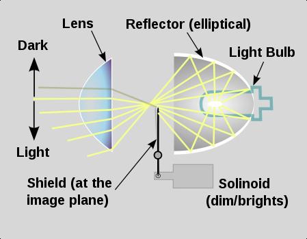
The time has come to test out the MLED setup from Morimoto, there will be a lot to follow from this Mopar1973man.com project so keep an eye out First shots wired up to a spare battery using a spare connector. Nothing installed yet. First thoughts. The hotspot is WOW I dont know that this would be a good setup for a car because of the foreground light that these would put out. However the truck should be high enough to not matter. The lux tests show impressive light in the hotspot compared to even the D2S 4.0 setup. Width isn't as good as the HID setups I have seen, but it is not terrible. It is approx the same as the mini h1 setup I had, but the D2S 4.0 would be better width. The project. I will be doing a retrofit into the new 4th gen showing how to accomplish better lights for the Quad headlight trucks out there. The big perk of the LED projector is the ease of install when it comes to dealing with the canbus system. HID's require special things to make it work, these "should" work out of the box, that is left to be seen however. There is also less stuff to wire up and get routed. If you have seen the headlight area of the headlights in a 4th gen you will know that is a good thing. HID vs LED HID projector ** Note the bulb sits in the center back of the reflector for a 360* reflection of light through the lens. LED ** note the LED shines directly up into a half moon reflector. Look out for more to come!
-
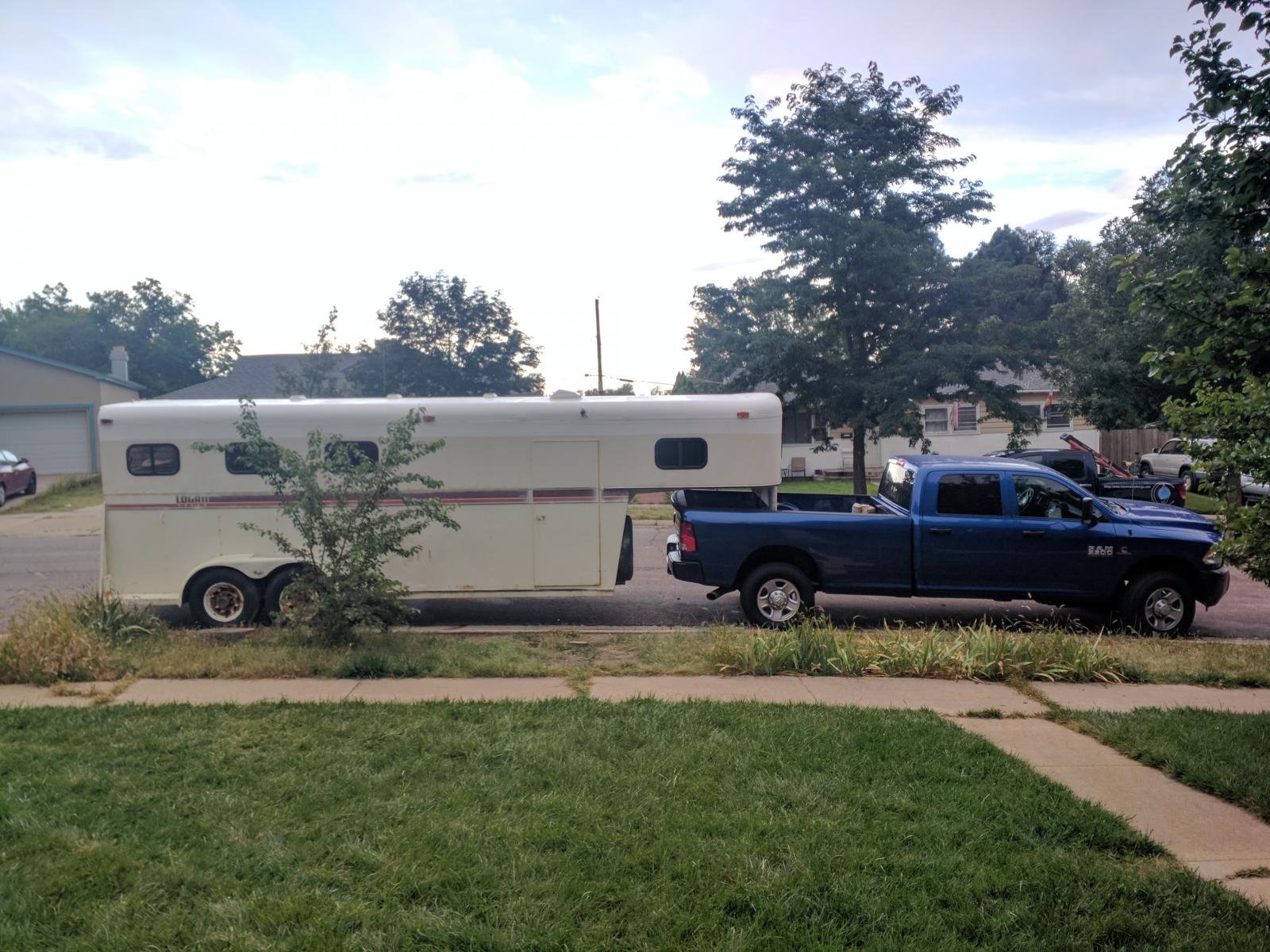
I think a new trailer is after we pay off the truck. I am tired of working on stuff lol
-
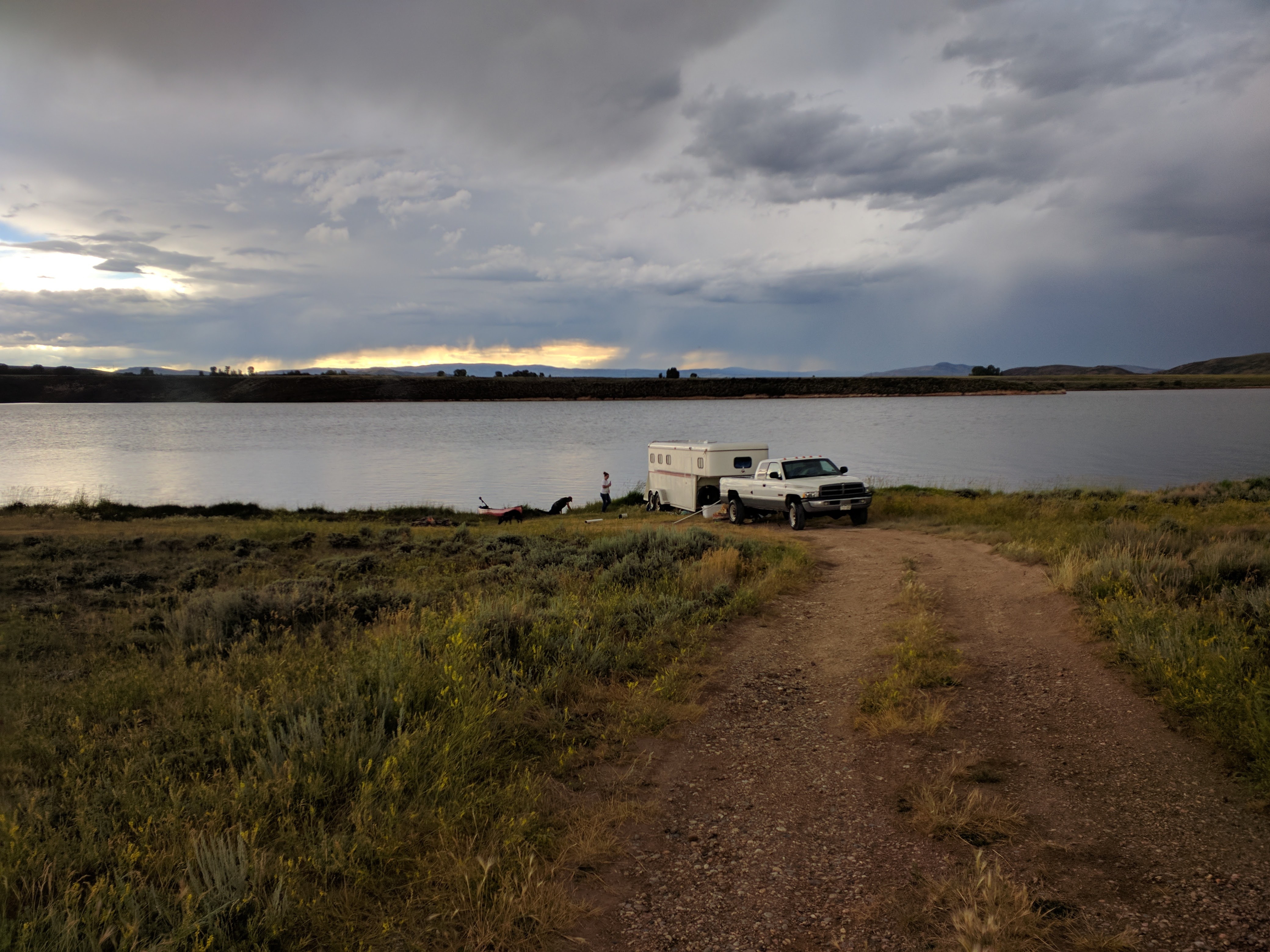
Here you go @Mopar1973Man tow mirrors flipped up and ready for action.
-
This covers the PowerTrain / Engine / Trnas Wiring Diagrams for a 2018 RAM HD truck. This should work for most Late Model 4th Gen Trucks. Engine Wiring AC system wiring Aftertreatment system Wiring Charging System Wiring Cooling System Wiring DEF System Wiring EGR System Wiring Fuel Injection control system Wiring Lift Pump fuel Delivery System Wiring Intake Air system Wiring Speed control system Wiring Starting System Wiring Throttle Control / APPS System Wiring Transmission Wiring 68rfe Wiring AS69RC Wiring G56 Wiring Engine Wiring AC system wiring Aftertreatment system Wiring Charging System Wiring Cooling System Wiring DEF System Wiring EGR System Wiring Fuel Injection control system Wiring Lift Pump fuel Delivery System Wiring Intake Air system Wiring Speed control system Wiring Starting System Wiring Throttle Control System Transmission Wiring 68rfe Wiring AS69RC Wiring G56 Wiring View full Cummins article
-
This covers the PowerTrain / Engine / Trnas Wiring Diagrams for a 2018 RAM HD truck. This should work for most Late Model 4th Gen Trucks. Engine Wiring AC system wiring Aftertreatment system Wiring Charging System Wiring Cooling System Wiring DEF System Wiring EGR System Wiring Fuel Injection control system Wiring Lift Pump fuel Delivery System Wiring Intake Air system Wiring Speed control system Wiring Starting System Wiring Throttle Control / APPS System Wiring Transmission Wiring 68rfe Wiring AS69RC Wiring G56 Wiring Engine Wiring AC system wiring Aftertreatment system Wiring Charging System Wiring Cooling System Wiring DEF System Wiring EGR System Wiring Fuel Injection control system Wiring Lift Pump fuel Delivery System Wiring Intake Air system Wiring Speed control system Wiring Starting System Wiring Throttle Control System Transmission Wiring 68rfe Wiring AS69RC Wiring G56 Wiring
-
This article covers the Fuse and relay Wiring for a 2018 RAM HD truck. It should be the same for most late Model 4th Gen RAM Trucks PDC Layout Battery Fuse and Relay wiring ASD Fuse and Relay wiring Misc fuse and Relay Wiring Run State Fuse and Relay Wiring Run / ACC State Fuse and Relay Wiring Run / Start Fuse Relay Wiring Upfitter No PTO Layout Upfitter PTO Layout Upfitter Fuse and Relay Wiring PDC Layout Battery Fuse and Relay wiring ASD Fuse and Relay wiring Misc fuse and Relay Wiring Run State Fuse and Relay Wiring Run / ACC State Fuse and Relay Wiring Run / Start Fuse Relay Wiring Upfitter No PTO Layout Upfitter PTO Layout Upfitter Fuse and Relay Wiring View full Cummins article
-
This article covers the Fuse and relay Wiring for a 2018 RAM HD truck. It should be the same for most late Model 4th Gen RAM Trucks PDC Layout Battery Fuse and Relay wiring ASD Fuse and Relay wiring Misc fuse and Relay Wiring Run State Fuse and Relay Wiring Run / ACC State Fuse and Relay Wiring Run / Start Fuse Relay Wiring Upfitter No PTO Layout Upfitter PTO Layout Upfitter Fuse and Relay Wiring PDC Layout Battery Fuse and Relay wiring ASD Fuse and Relay wiring Misc fuse and Relay Wiring Run State Fuse and Relay Wiring Run / ACC State Fuse and Relay Wiring Run / Start Fuse Relay Wiring Upfitter No PTO Layout Upfitter PTO Layout Upfitter Fuse and Relay Wiring
-
This covers the Chassis Wiring for the 2018 ram hd trucks. this should be the same for most late model 4th gens. Tire Pressure Monitor Wiring Transfer Case Dial Range Selector Wiring Transfer Case Manual Range Selector Wiring Brake System Wiring Trailer Wiring 5th Wheel Prep Group Wiring Trailer Wiring Cab and Chassis Non-5Th Wheel Prep Group Wiring Trailer Wiring Non-5th wheel Prep Wiring Axle Lock Wiring Tire Pressure Monitor Wiring Transfer Case Dial Range Selector Wiring Transfer Case Manual Range Selector Wiring Brake System Wiring Trailer Wiring 5th Wheel Prep Group Wiring Trailer Wiring Cab and Chassis Non-5Th Wheel Prep Group Wiring Trailer Wiring Non-5th wheel Prep Wiring Axle Lock Wiring View full Cummins article
-
This covers the Chassis Wiring for the 2018 ram hd trucks. this should be the same for most late model 4th gens. Tire Pressure Monitor Wiring Transfer Case Dial Range Selector Wiring Transfer Case Manual Range Selector Wiring Brake System Wiring Trailer Wiring 5th Wheel Prep Group Wiring Trailer Wiring Cab and Chassis Non-5Th Wheel Prep Group Wiring Trailer Wiring Non-5th wheel Prep Wiring Axle Lock Wiring Tire Pressure Monitor Wiring Transfer Case Dial Range Selector Wiring Transfer Case Manual Range Selector Wiring Brake System Wiring Trailer Wiring 5th Wheel Prep Group Wiring Trailer Wiring Cab and Chassis Non-5Th Wheel Prep Group Wiring Trailer Wiring Non-5th wheel Prep Wiring Axle Lock Wiring
-
This Article cover the Canbus Layout and Wiring Diagrams For a 2018 RAM HD. This should be the same for most late model 4th gen trucks Canbus C Layout Diagram Canbus C Wiring Canbus Private Wiring DataLink Wiring Canbus IHS Layout Diagram Canbus IHS Wiring LIN Network Layout Diagram Lin Bus Network Wiring Vehicle System Interface View full Cummins article
-
This Article cover the Canbus Layout and Wiring Diagrams For a 2018 RAM HD. This should be the same for most late model 4th gen trucks Canbus C Layout Diagram Canbus C Wiring Canbus Private Wiring DataLink Wiring Canbus IHS Layout Diagram Canbus IHS Wiring LIN Network Layout Diagram Lin Bus Network Wiring Vehicle System Interface
-
Here are the wiring Diagrams for the 2018 RAM HD Body Wiring. This should work for late year 4th gens. BCM Layout Air Suspension 3500 Wiring Air Suspsension 2500 Wiring Stereo Base Non-alpine Wiring Stereo Premium Alpine Wiring Stereo Media Port Wiring Backup Camera Cab and Chassis Wiring Backup Camera Wiring Defog Wiring Door Locks Wiring Window wiring Hands Free Wiring Heated Seats Wiring Heated Steering Wheel Wiring Horn Wiring Hvac Automatic Control Wiring Hvac Manual Control Wiring Interior Lighting System wiring Message System Wiring Mirrors Base Model Wiring mirror Premium wiring Park Assist Wiring Passive Entry Lock system Wiring Pedal Adjustable power Wiring Power Outlet Wiring Seat Belt Wiring Seats Power Memory Wiring Setas Power Wiring RamBox Lock Wiring Sunroof Wiring Tailgate Locking Wiring Theft Security System wiring Wiper Wiring Exterior Lights Backup Light Wiring Headlight Quad lights Wiring Headlight Projector Wiring Fogs wiring Parking Lights Wiring Brake Light Wiring Turn Signal Wiring BCM Layout Air Suspension 3500 Wiring Air Suspsension 2500 Wiring Stereo Base Non-alpine Wiring Stereo Premium Alpine Wiring Stereo Media Port Wiring Backup Camera Cab and Chassis Wiring Backup Camera Wiring Defog Wiring Door Locks Wiring Window wiring Hands Free Wiring Heated Seats Wiring Heated Steering Wheel Wiring Horn Wiring Hvac Automatic Control Wiring Hvac Manual Control Wiring Interior Lighting System wiring Message System Wiring Mirrors Base Model Wiring mirror Premium wiring Park Assist Wiring Passive Entry Lock system Wiring Pedal Adjustable power Wiring Power Outlet Wiring Seat Belt Wiring Seats Power Memory Wiring Setas Power Wiring RamBox Lock Wiring Sunroof Wiring Tailgate Locking Wiring Theft Security System wiring Wiper Wiring Exterior Lights Backup Light Wiring Headlight Quad lights Wiring Headlight Projector Wiring Fogs wiring Parking Lights Wiring Brake Light Wiring Turn Signal Wiring View full Cummins article
-
Here are the wiring Diagrams for the 2018 RAM HD Body Wiring. This should work for late year 4th gens. BCM Layout Air Suspension 3500 Wiring Air Suspsension 2500 Wiring Stereo Base Non-alpine Wiring Stereo Premium Alpine Wiring Stereo Media Port Wiring Backup Camera Cab and Chassis Wiring Backup Camera Wiring Defog Wiring Door Locks Wiring Window wiring Hands Free Wiring Heated Seats Wiring Heated Steering Wheel Wiring Horn Wiring Hvac Automatic Control Wiring Hvac Manual Control Wiring Interior Lighting System wiring Message System Wiring Mirrors Base Model Wiring mirror Premium wiring Park Assist Wiring Passive Entry Lock system Wiring Pedal Adjustable power Wiring Power Outlet Wiring Seat Belt Wiring Seats Power Memory Wiring Setas Power Wiring RamBox Lock Wiring Sunroof Wiring Tailgate Locking Wiring Theft Security System wiring Wiper Wiring Exterior Lights Backup Light Wiring Headlight Quad lights Wiring Headlight Projector Wiring Fogs wiring Parking Lights Wiring Brake Light Wiring Turn Signal Wiring BCM Layout Air Suspension 3500 Wiring Air Suspsension 2500 Wiring Stereo Base Non-alpine Wiring Stereo Premium Alpine Wiring Stereo Media Port Wiring Backup Camera Cab and Chassis Wiring Backup Camera Wiring Defog Wiring Door Locks Wiring Window wiring Hands Free Wiring Heated Seats Wiring Heated Steering Wheel Wiring Horn Wiring Hvac Automatic Control Wiring Hvac Manual Control Wiring Interior Lighting System wiring Message System Wiring Mirrors Base Model Wiring mirror Premium wiring Park Assist Wiring Passive Entry Lock system Wiring Pedal Adjustable power Wiring Power Outlet Wiring Seat Belt Wiring Seats Power Memory Wiring Setas Power Wiring RamBox Lock Wiring Sunroof Wiring Tailgate Locking Wiring Theft Security System wiring Wiper Wiring Exterior Lights Backup Light Wiring Headlight Quad lights Wiring Headlight Projector Wiring Fogs wiring Parking Lights Wiring Brake Light Wiring Turn Signal Wiring


