balsip
Unpaid Member
-
Joined
-
Last visited
Everything posted by balsip
-
I would be surprized if cranking dry for a short period would cause damage as this happens all the time with diesels. I would crack one injector (1,2,3,4 while 5&6 are too awkward) at a time while cranking and check for fuel with a piece of cardboard or paper towel with rubber gloves(not thin latex ones) and glasses over the eyes. That 25,000 psi fuel cuts skin easily so be careful to keep away from spray. There are some mechanical failures in the VP44 that will not throw a code. You can attach a pressure guage at the VP44 fuel inlet to check low pressure fuel system. This is after the filter right at the VP44 inlet so a plugged filter will show. A guage with proper schraeder fitting is about $40 or less. If you just bump the starter quickly the LP pump will activate for a full 30 seconds for checking pressure even though engine does not start. You could disconnect the return flow at the rubber splice in the metal line and use a fuel line hose into a jar to check return flow. The banjo fitting at the exit of the VP44 has a ball and spring pressure regulator plus a fixed bleed hole. I am not sure of the expected flow while cranking since the VP44 is noted for very low flow at idle. I thought that 911 had some lubricity additive in it to counter the dryness according to the label? I would just add some outboard two stroke oil rather than drain tank. Once you prove that you have fuel going to injectors you know you should start as long as compression is good. Have you downloaded the FSM in the download section on this site so you can read the VP44 troubleshooting section?
-
The APPS has two digital signals as well as the analog signal for "pedal position". These two signals are labelled something like: a) "AT IDLE POSITION" and b)"NOT AT IDLE POSITION". When at idle a) should be TRUE and b) should be FALSE. The ECM should try to maintain a fixed idle RPM of about 850RPM with some "droop". When pedal is pushed then we go to a second mode where we add fuel proportionally to pedal position but do not try to maintain a fixed RPM otherwise this could cause accidents. That is why they use two signals rather than one since this is such a safety issue in "fly by wire" systems. I believe your truck has the APPS out of calibration such that it looks like you are a) =FALSE & b)=TRUE with no foot on pedal. The enginners probably designed it to maintain closed loop speed control for the first 10 seconds of start-up regardless of the two digital signals and that is why a quick Drive engage is okay. You can backprobe these signals at the APPS connector with a DVM and safety pin. TRUE is roughly 2.5 volts or higher(5 volt max possible). FALSE is about 1.0 volts or less. The calibration is done carefully with those screws that are "locktited". The TIMBO APPS gets around this by having a bigger deadband in the potentiometer at idle position. I am taking some educated guesses at some information in the above but I believe it is fairly accurate. Someone correct me if I am wrong. I think it is worth looking into. So few people have this stalling problem that it is because few people have their APPS out of calibration unless they have had someone working on it. Even the new ones come with the bracket calibrated as long as those screws are not moved. The Timbo uses the old bracket without calibration because it has deadband.
-
I totally believe that the problem has to do with the VP44 pump variability in rebuilds as outlined above althogh it is influenced by all the other parameters such as "fluid coupling drag" of the TC and replacement of the injectors with RV275's. This is a "closed loop control system" where the ECU is the brain (controller)and the VP44 is the output actuator, while the injectors highly influence the the "loop" gain and therefore influences the final "loop error" in terms of RPM. Loop Error = setpoint RPM(your foot on the APPS) - measured RPM (from the CPS).Also the tuning parameters in the ECU are different for "ON IDLE" and "OFF IDLE" states wrt the APPS position and accounts for why blips on the throttle can influence the stall outcome. The reason I think the VP44 has the biggest influence is that it has the biggest variability in quality of the rebuild on a very complex and critical component in the loop. Also, there are relatively few owners having this problem - much less than the number of owners with RV275, triple lock TC's, etc. We all end up guessing the cause because we are operating in the dark as only Dodge engineers know the software strategy deployed in the ECM. I doubt if even dealers are told about strategy via TSB's as they have a hard time dealing with even the simpler computer tasks.
-
I took a look in the FSM (manual) in the wiring section at the APPS. As you probably know the APPS supplies a voltage proportional to you right foot but it also supplies two digital TRUE/FALSE signal to the PCM labeled as follows: 1)ON IDLE 2)OFF IDLE. I would probe these two signals when at idle position to make sure ON IDLE is TRUE and OFF IDLE is FALSE since this affects the PCM software tuning for RPM speed control very strongly. You can back probe these at the PCM connection using aligator clips and a safety pin and of course a DVM. Just keep the two leads from shorting together. You should be able to do it with engine off but key in ON position(guessing). When "on idle" the software will try to hold a relatively strong closed loop control on RPM but once "OFF IDLE" it will let your brain and your foot be the "closed loop". Just the fact they used two digital signals to verify the same "idling" state tells you how important this state determination is. I would check that out.
-
I have read that there is a built in "droop" in the ECM software that is stronger in the auto than the manual ECM. Droop means that the actual RPM is lower than the setpoint RPM as load increases. You can read about droop in the VP44 Smart Controller in the download section that the Cummins ECM mimicks. The guys with a manual tranny know this because they can start off from a dead stop without applying any throttle. Dodge asked Cummins for this on purpose I believe in case the lock-up clutch stays engaged(stuck relay contacts), but they did not count on all the mods and extra drag that can happen. I also suspect the "sampling time" is in the order of 4X per second meaning each update to the VP44 is 0.25 seconds apart approximate. The software may also be written such that there is a maximum speed correction per 0.25 sec sample execution which explains why P to R to N to D avoids the stall. It gives more samples to get up to speed. Surging can result otherwise with such low sampling time. There is some speculation on my part in the above comments but I have read quite a bit on this governor and my former career was as a process control engineer using microprocessors. If you have a Timbo APPS I would wonder if the "idle position" signal is a problem since Timbo uses extra deadband to eliminate APPS calibration. The ECM treats the "off idle" control tuning differently than the "on idle" tuning. Perhaps it would be worth measuring the APPS voltage at idle and make sure it is within spec before doing anything? The other angle to consider is the return pressure regulator on the VP44. Most injection pumps are very sensitive to this pressure, especially the P pump where many owners stretched the spring a bit to increase pressure and avoid stalling at idle in cold weather start-ups. The VP44 is a little different in that the flow is so critical to lubrication that they have the spring+ball AND a drilled bypass hole. So you can test that backpressure theory by squeezing the short rubber splice section a bit with locking pliers but do not squeeze completely off (do not starve the lubrication aspect) and see if it changes things. One possible solution(last resort?) is to use the neutral/park start lockout switch on the tranny to engage a 2 second "time delay off" relay to add a bias voltage onto the APPS for two seconds. ie. A switched resistor connected to the 5 Volt reference supply could add 200 extra RPM to the ECM APPS signal input but this is last resort. I have used a 555 timer chip for this type function but Toff Delay relays are available with this built in. Just some thoughts to consider.
-
These are "torque to yield" head bolts so many owners buy new so as to not take a chance. ie. tighten to a torque then go part of a turn more. Compare length of all bolts to make sure none are longer on the thread to make sure there has been no tightening beyond yield. Push threads of two bolts against each other as if one was a thread gauge and check for any variation against a bright light if you can get my drift.
-
I think you are "hot on it" with the idea of exhaust gases getting back to the tank. I had the exact same problem when Dodge dealer changed VE44 in my 91.5 in 1996. Cummins used to have very brittle black-blue paint that was sprayed over the engine AFTER final assembly that came off when working with wrenches. The Dodge mechanic was so careless he got some flakes in an injector and it prevented the injector pintle from closing after "pop off". The symptom was milder surging (than yours)at idle only as the mechanical governor tried to compensate. I think the VP44 electronic governor might be more sensitive and cause the extreme surging you have as it tries to get correct idle RPM. I put in clear PVC tubing on both supply and return lines and I could see the bubbles start in the return line (exhaust gases from injectors) and then suddenly re-appear in the supply side due to the small pick-up chamber in the tank. You can imagine the the foamy diesel in the pickup chamber in the tank with exhaust gases getting in there. There is a small 3 inch section of rubber fuel line on the supply side of the VP44 that you could substitute a loop of 12 inches of clear PVC temporarily. I only tested in the driveway since PVC was not rated for fuel and I was afraid of diesel fire while driving. The rubber piece in the return on the 24V is of no use since only the VP44 overflow portion is accessible there - the injector return flow joins in a T connector at the very back of the engine before going to the tank pick-up. There is more to my story about the incompetence of that mechanic at a 5 star facility but I will leave that for now. It cost Dodge two injection pumps and at 2 dealers, a mechanic's job(I surmize since he was gone quickly), over 25 hours labour and finally re-imbursement to me for my own final repairs when they could not handle it. --- Update to the previous post... JLWelder, I put a file under downloads, "Other Manuals and Documents", called "VP44 Smart Digital Governor" that is used for gensets, pumps etc. It is probably functionally equivalent to what Cummins implemented in the ECM of the 24 V and gives a lot of insight to the Cummins ECM functionality. This governor works with 12V or 24 systems. One item of interest to you is on page 17 under Troubleshooting with a symptom of "Engine Unstable" with a cycle of 0.5 sec to 1.0 sec caused by the battery being less than 20 V on a 24 V system (or less than 10V on our 12V system). Look at the wiring to the VP44 and it shows only six conductors to the ECM: CAN H&L(serial communication), +V, GND, DZG(timing derived from Crank, cam teeth), MAS (master shutdown). I would measure voltage with safety pins piercing +V & GND with a DVM just before the final VP44 connection to see if there is a bad connection or ground and compare to voltage accross battery while it is surging. I believe surging as described above is more likely but this write-up saved 3 months ago caught my attention to your problem. Good luck, I love your persistence in this.
-
The other possibility is to check the connector at the VP44 especially if you have had it off in the past. Be careful as there is a release that pulls out evenly (top and bottom) that releases plastic tabs on the pump. It is easy to damage the connector release if you force it. Ask me how I know (fortunately I had some very good ABS plastic epoxy). Perhaps just try wiggling gently first to see if things change. I kind of think the problem is in the pump as many say the solder on the VP44 circuit board deteriorates with heat and age having no lead in it. It is all surface mount technology so very difficult to repair without proper optical soldering tools. There is a little processor that is built in there that communicates CAN II protocol to the ECM (Cummins engine computer)via the cable that then provides the so called "companion codes" to the PCM (Dodge design computer) with the ODB II (code reader) connector. Three levels of processors to get some of those codes out. If I get 450,000 miles out of mine I would be very happy. I think the average is more like 130,000 miles.
-
I submitted the repair procedure in the the Downloads section under "other documents" but you will have to wait until Michael looks at it before it is visible. It is for a 12V but should apply to early 24V if that is what you have. Has a great description and very good pictures of pulling the camshaft. There is a heat method of pulling the cam gear off the cam instead of removing the whole cam but that is usually reserved for experienced Cummins mechanics. The gear is heat treated for hardness so one has to be careful with a torch.
-
Downloads have been submitted but here was the Recall 8001 notice: http://dodgeram.info/tsb/recalls/8001.htm Of course there is no mention of the EPA lawsuit on "defeat devices" in the recall but you can be sure that it did happen! The recall was because the ECM software advanced timing as engine hours passed threshold values. Everyone used to exclaim in the forums: "Put some miles on that new truck and your mileage will go up 3 MPG!" The VP44 was the first pump that could dynamically control timing with RPM and load but full advantage of the engine efficiency could not be achieved legally. Prior to the ISB the timing stayed constant through the RPM range which was a huge disadvantage at high RPM (2000+ RPM) were injection combustion delay was significant.
-
Mine did not come on in a 2000 but I imagine the rules were updated afterwards. By law they were supposed to put an update sticker on the ECM located behind the fuel filter with the date and the software Release number. A flashlight and mirror should be good to see it. The defeat software only lasted about 6 months (production starting July 1, 1998) before the EPA caught on. I have both the final announcement on the one billion dollar settlement plus the "Consent Order" to Cummins outlining the settlement for complete access to the manufacturing/engineering design/testing facilities(unsigned version). I will download it but Michael looks them over before they appear. I will submit to Other Manuals and Documents.
-
I just replaced my VP44 injection pump and mileage went from 17.7 to 19.7 for a 2 mpg increase. My injection pump had the P0216 code which means the timing piston was binding up and full advance could not be achieved. I would check the codes since the MIL light does not show when there is a P0216 code. I am also thinking of the Diablo Puck D7153 for the 2000 year I have. Apparently it adds 50 hp which is probably the limit for a stock auto but it advances timing and most claim a couple of mpg increase. Timing has a lot to do with the decrease in mpg since the 1st Gens. Most owners will remember when the ISB first came out in 98.5 Cummins had the ECM programmed so the timing (and mileage) would go up as the odometer went up. This was so it would pass the initial federal emission (EPA) tests. Navistar, Cummins and Detroit Diesel were fined over one billion dollars on this. Owners were puting padlocks on their ODBII connector so Dodge dealers could not retro-load the retarded timing software when in the dealer for service. The retarded timing and DPF's in 2007.5 is the reason most 2010 Dodges get about 30% worse mileage than us. It is not because of a heavier vehicle or more horsepower as the manufacturers would like us to believe. I have the court documents and press release in Adobe format if Michael wants it in the download section. It was picked up off the EPA site.
-
The reason your alarm is going off is that there is an intermittent switch contact on your drivers side "Cylinder Lock Switch". That switch is the means that the security system knows that the rightful owner of the truck is using his key to enter the truck so the alarm does not activate. If the key is not seen and the door switch looks open then the security system thinks that there is a B&E. Look at wiring diagram 8W-39-4 in the 2001 FSM in the download section. I would take the interior panel off the door and look at it and see if it is rusty or greasy. Perhaps some cleanup or contact cleaner will help. Just as a side note the computer only arms the system either via the armrest lock switch or the remote module. If you use the manual lock button the computer has no digital input on this switch and can not arm. I believe the lock tumbler will arm the system but I would have to check FSM.
-
I visited the site and my Microsoft Security Essentials immediately detected a virus trying to be sent to my computer. Fortunately my PC software was cleaned afterward (probably a corrupt cookie script pulling private information from my computer?). I am guessing at the purpose.
-
My experience with surging has been exhaust gas getting in the return line from a sticking open injector or sucking air on the supply line from the tank.The easy way to check is by putting a short section of clear PVC tubing in series where the supply to the VP44 has a short rubber hose to give flex when servicing. You need to watch carefully right from a cold start since the bubbles magnify by going via return line into the pickup chamber in the tank and come back worse in the supply side. A mechanical pump governor (the 89 to 93 Bosch VE44) will surge 650 to 1000 rpm while a a computer controlled governor like the VP44 may be worse. Remember those bubbles are compressed back to nil at 17,000psi and the pump sees a smaller fuel charge from the variable displacement injection pump. The governor sees the lower engine speed due to bubbles and tries to up the displacement and a surging cycle starts. Do not leave that PVC section in too long since it is not rated for diesel fuel.The reason I know the above is that two dealers, two VE44's on warranty, and 10 hours of Chrysler diagnostic authorization could not find my surging until I started talking to Cummins technical support directly myself. A dealer had gotten flakes of that brittle black Cummins paint into the injector lines when replacing my VE44 on safety campaign in 1996 causing exhaust gas to enter the return fuel line.
-
The factory service manual for a 2001 in the Download section explains how to fix it. Just remember the seal is installed with a special tool that can easily be made by using a length of allthread, some nuts and washers. The pictures in the FSM are good for showing what is required. The seal is accessible through the vacum 4X4 actuator housing once the cover is removed and the half axle and center axle is removed. I have to replace the seal in my truck once it gets worse or I have the time.
-
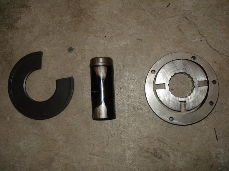
I just replaced mine two weeks ago. I would price it at a local Bosch dealer since they make sure that the diaphragm is updated and you do not get that 0216 code so easily next time. When I mentioned that I was going to mail order from PDR, the Bosch dealer offered "vendor price" at $1,375 which is a good price for Canada where we always pay more. Supposedly the diaphragm is thicker since 2003 and the electronics is updated since 2006 to be more heat tolerant. Seals are also improved for ULSD. One piece of advice - use the Blue Chip Diesel VP44 install instructions (Google it) since they recommend only removing 1,2 & 4 injector tubing as a bundle and leave 3,5,& 6 attached at the injectors and supports. Never loosen any blue colored plastic clamps as these are sensitive to the high pressure injection pulsations. Of course you have to remove all 6 connectors at the pump. You will easily be able to sneak that pump out and it saved 1 to 1.5 hours of knuckle busting to reach No 6 injector. Also, use a small dab of yellow paint on leading edge of key so it is easily visible with a mirror when installing to make sure keyway is lined up exactly before tightening the big nut. If key is at all loose in shaft keyway before installing, you can center punch the side to cause more friction in the keyway so it does not fall out during installation. Mine was tight out of the box.Those two back nuts on the mounting of the VP44 are hard to get at. I wrapped a turn of masking tape around the nut to make sure the socket was tight on the nut but still allow socket to be removed once threaded on the stud. You do not want to fish for those nuts if they drop once pump is initially installed with keyway lined up. This install is much easier than a VE44 since no dial gauge is required in the spill port to time it. (The ECU software corrects for timing variances by synchronizing to a missing tooth on cam or crank sensor indicating TDC). Here is the carnage: Diaphragm is on Left - note the missing piece that cracked then fell out.the timing piston is in the middle and the Right is the VP44 internal low pressure vane pump with the vanes removed.
-
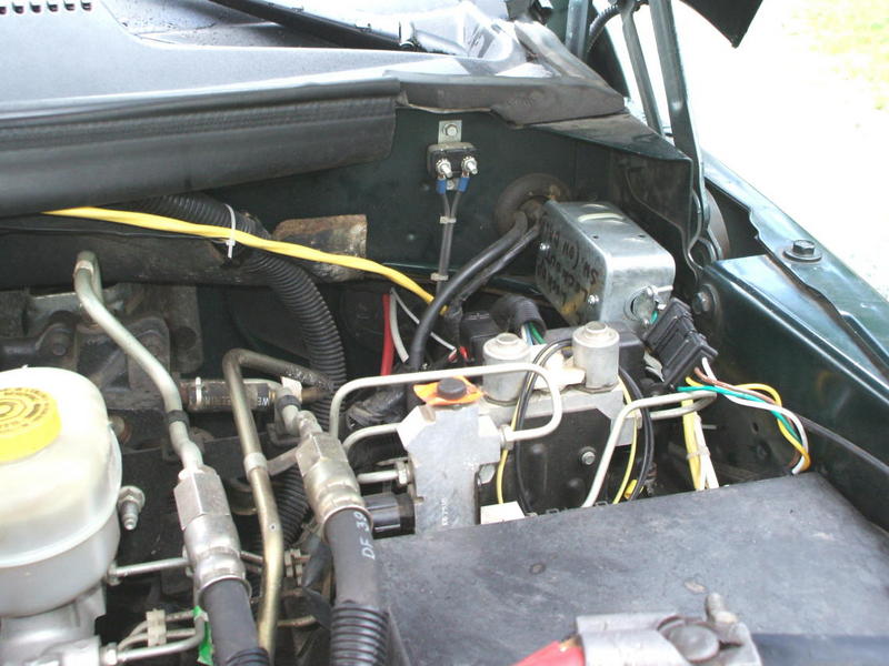
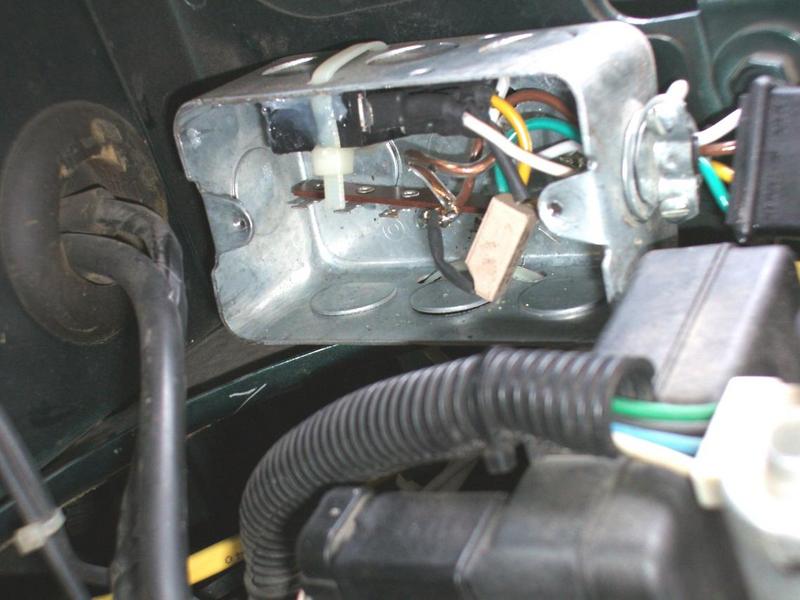
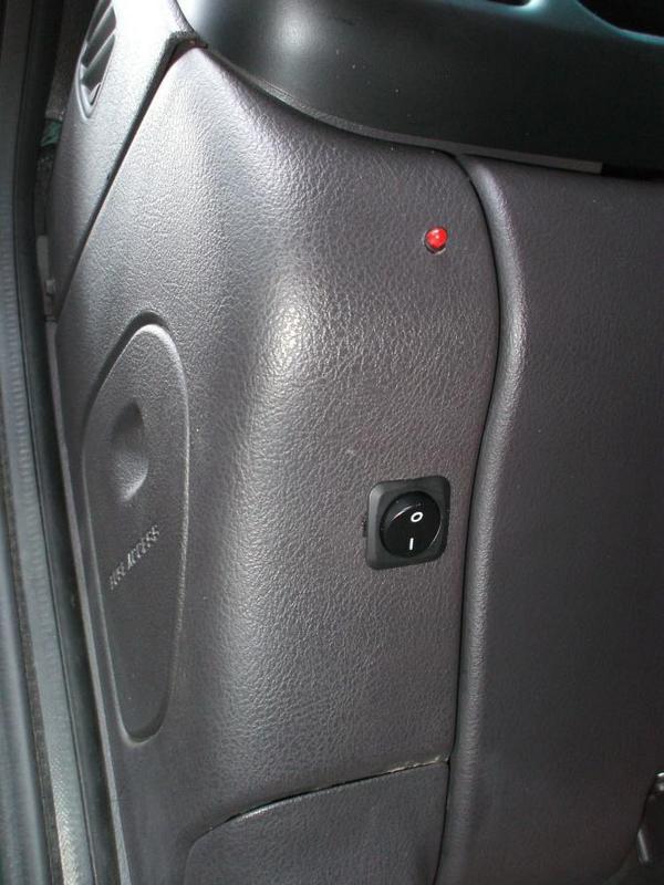
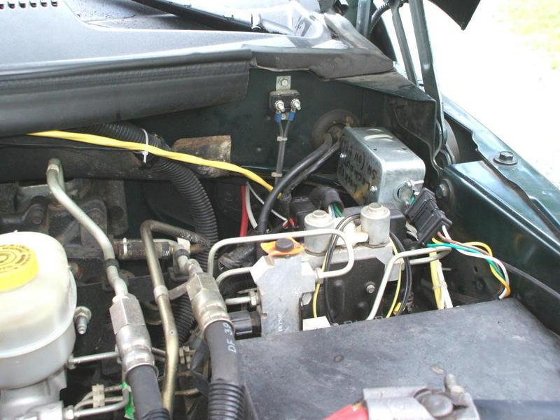
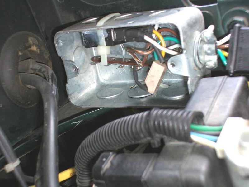
I would recommend that the TC stay locked when towing hard to keep heat down. I mainly use this switch to unlock in the city to keep the TC from cycling lock/unlock since it is the prime cause of 47RE premature failure. When the TC clutch slips the debris gets stuck in the anti-drainback valve and blocks fluid flow and that is the end of the tranny. Many rebuilders remove the drainback valve which my 91.5 did not have from new. It just takes 10 seconds to fill the TC on startup before you can feel engagement. Anyway here are the promised pictures. The 1st is the switch on the dash with a BD low fuel pressure light just above it. I put it on left drivers side near fuse panel for easy access. The power was taken from the "fuse tapper" that came with the low pressure kit and was intalled on the 10 amp radio fuse. Extra load is 0.1 amp max. (or 100 mA). The relay is only energized when the dash switch is ON and the ignition key is in ON or ACC position.Left drivers side dash at fuse panel. The electrical box with relay and switched 150 ohm 5 Watt resistor under hood. Yellow wire is two conductor that is connects to C2 at PCM to tap into the TC solenoid wire OR/BK.Under hood installation The guts of the electrical box. I used flat blade connectors insulated by heat shrink to connect to relay and prevent shorts. Tie wraps are handy to keep box steady and parts from vibrating.The relay box with a NAPA relay basically same as those used extensively in the power distribution box (the big black box with fuses, fuseable links, relays beside the drivers side battery). Note the 4 conductor trailer connector for easy removal if ever required. I put this under the hood(rather than the dash) because I did not want to complicate the procedure for removing the dash when an HVAC exchanger needs service down the road. Let me know if any clarification is needed and good luck.
-
Let me know if you want a picture of the installation. There are probably better boxes than a duplex electrical box to stuff the relay in but it did the job. Also, you may be able to find a relay socket easier than I could here in the far North. Radio Shack (the Source in Canada) has a black rocker switch that matches our dash in the Dodge that makes it look "factory installation".I am wondering whether your haze may be due to the need for more air from the turbo? A 100 hp increase at injectors may need a small orifice leaking to atmosphere on the actuator air line (via a brass fitting) to make it open wastegate later and provide more air for combustion? The other possibility for the haze mentioned to me is too thick of a copper washer on the injectors causing the injectors to be too far out of the combustion chamber. I know my 91 has 0.030 washers and produces haze at idle since they should be 0.020 which I stupidly missed in the instructions when installing. I'll change them next time I clean the injectors.
-
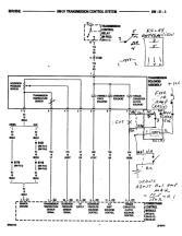
Here is the circuit. I used pdftown's 2001 Ram manual to get the original factory cct drawing in sec 8W-31 page 3. I can thank this site for that! I just copied it and marked my changes in pencil as a guide. It is a simple enough circuit but it was surprising how long it took me to make it look good when putting it together. I used the same 5 pin relay used in the power distribution centre under the hood on the drivers side fender. I bought a spare at an auto supply store. I did not have the proper socket for the relay so I used female blade crimp on connectors instead. I added heat shrink to each one to make sure no shorts could happen. All the circuit was put in a 120 VAC metal wall switch box (surface mount type that has rounded corners and blank metal cover) and used a 4 conductor trailer connector so I could easily remove it for maintenance. I tie wrapped the relay to the side and dabbed it with silicone to make sure it would not move in the box. SPST switch at bottom is the dash switch for the driver to turn the relay ON/OFF. OFF is the normally closed position of the relay so it defaults to TC clutch engaged. Do not use one of those lighted auto switches or the current for the LED could be a problem (would have to test relay pickup current). For a 12V supply I used the 10 amp radio cct that also supplies power to my LP Fuel Pressure Alarm so current is only drawn when key is in ON position so battery draw is zero while parked. The BD LP Fuel Alarm kit came with a "fuse tapper" so that made it easy to tap power off the fuse. By the way, a 1996 Ram can get away with a simple SPST switch with no limp mode. There will be a code in there but it will not light the MIL indicator and is hidden. The above circuit just makes the computer think it is still connected to the clutch solenoid coil at all times. It is measuring voltage across a small resistance in the I/O circuit that effectively checks for minimal current to show connection to tranny is good. I am not sure if I got this picture link right but I will try to learn how from others.

-
The main reason is reliability and longevity of the transmission. Many drivers do not realize that every time you release the throttle the lock-up clutch disengages. Because the Dodge diesel has a very loose TC (inefficient fluid coupling) the clutch has to absorb 300 to 500 of RPM difference when locking up. This was fixed with the 48RE since many heavy towers could not engine brake with an automatic. Anyway this yoo-yoo shifting in is not a problem at hiway speeds but in the city it puts a lot of extra wear on the clutch. I would prefer to lose the 5 to 10 per cent milage loss with it unlocked in the city unless on a long hill climb. I got 450,000 km out of my 91.5 Dodge non-lockup tranny and most people get much less with the 47RE lock-up TC. The 1999 to 2002 was especially demanding on the TC clutch because Dodge added an extra lockup in 3rd that really is not much use over the narrow band it is engaged.
-
I found my recent 2000 2500 truck aquisition very annoying constantly going in and out of lockup in the city or in hilly terrain so I installed a switch on the dash to disable the lockup solenoid. The extra lock-up sequence in 3rd gear was even more annoying as the 97 does not do this. This is not the "mystery switch" that forces a lockup and in fact is the opposite. The mystery switch is vey hard on the soft parts in the tranny when changing gears locked.I had done this in my 97 2500 and all I had to do was put a simple switch in to open the circuit to the solenoid. Last week I tried the same thing in the 2000 but it immediately went into 3rd gear limp mode. New software in the 2000 PCM so I had to take a different tact. I finally ended up switching in a 150 ohm 5 Watt resistor connected to switched 12V with a relay to make the PCM think the solenoid was still connected. The relay is activated with a round rocker switch on the dash that looks factory. The relay has a 75 ohm coil but the higher the resistance that does the job the less current required. If anyone else is interested I can post the circuit diagram. I basically cut and spliced in the circuit in series with the OR/BK pin 11 on connector C2 (middle of the three) on the PCM. No codes get set with this circuit. The relay can be eliminated by using a STDP switch but its hard to find one that looks factory. The switch has to be 2 position only and not a 3 position or a code will be set saying there is an "open solenoid circuit". The hardware is mounted immediately beside the drivers side hood hinge on the small ledge inside a small electrical box with a 4 wire trailer connector. This is my 1st post on this excellent site so I will fill in the signature once I figure out how.