


Tractorman
Yearly Subscription
-
Joined
-
Last visited
Everything posted by Tractorman
-
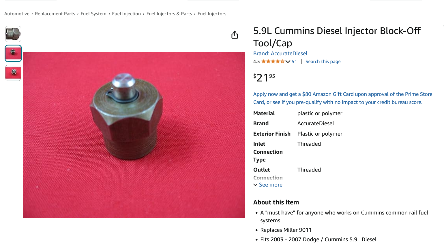
My knowledge is fairly limited regarding the 3rd generation trucks. If you don't already have these tools, a couple of tools I recommend would be a scanner that can read commanded rail pressure and actual rail pressure, and an injector block off tool. I have used them in the past and they have helped me diagnose a faulty injector. I know that when the engine is cranking, if the fuel rail pressure is below 4,500 psi, the ECM will not command injectors to fire. - John
-
My next step would be to inspect the pin connectors on the Smarty cable and the pin connectors in diagnostic connector under the dash, if you haven't done so already. If everything seems good there, then you might try contacting Smarty for help before you condemn the ECM. - John
-
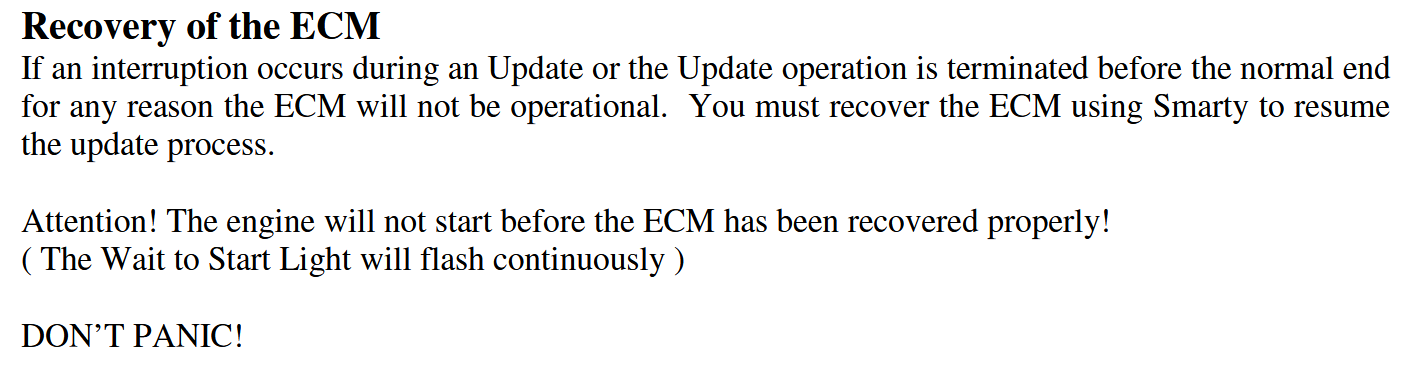
Have you tried "Recovery of the ECM" (page 9 of the Smarty S03 Instruction Manual)? This may fix your issue. - John
-
I don't see any benefit using the clear tubing. Once the engine has been run, there are literally thousands of tiny air bubbles in the system. The air bubbles will dissolve faster as the fluid warms or slowly each time the engine is turned off, but they will work themselves out. You are worrying too much about things that are not important. So, back to the drawing board. Are you saying that when the front axle is on jack stands and engine is running that there is no power steering assist at all? and no brake assist at all? Are you keeping the reservoir constantly topped off when you are doing this test or other tests? Try to think this through before you make your next move, so that your next move will count. We are here to help (or hinder) you. Also, to answer a question that I forgot to answer..., on my truck, the return line from the brake booster is closest to the engine block when the pump is mounted. I don't think it would matter for the problem you are having, but by design there could be better mixing of fluid in one return port vs. the other. - John
-
I think it will be good for you to take a break from this - should help to clear your mind. In the mean time I will attempt to offer an explanation of how the power steering / brake hydroboost system works. The power steering pump and its integrated flow control / relief valve are fastened to the reservoir. The power steering pump is a fixed displacement vane pump. The flow control valve portion of the integrated flow control / relief valve ensures that there is always about 3 gpm of power steering fluid flowing, regardless of engine rpm. This steady flow of fluid gives the steering a good feel under all operating conditions. The relief valve portion of the flow control / relief valve is set at about 1450 psi (not the 4500 psi previously mentioned). Its purpose is to set a maximum pressure to allow work to be done and to also protect the pump and other components within the system. Since pressure is directly related to resistance to flow, the pressure in the system will always vary and will only reflect the work being done by steering or brake applications at any given moment. Most of the time the power steering pump is operating at a pressure far, far lower than the power steering relief valve setting. Power steering fluid leaves the pump at 3 gpm and passes through the brake booster control valve at 3 gpm and then passes through the steering gearbox control valve at 3 gpm and finally arrives at the reservoir at 3 gpm. There is always 3 gpm of power steering fluid flowing through the system regardless of engine rpm and regardless of what components are being operated. The ONLY time fluid flow will be stopped is if the pressure of the fluid is forced to rise above 1450 psi - then the fluid will return directly to the reservoir via the internal relief valve. So, actually the pump will still be providing 3 gpm of flow, but the flow will be returned immediately to the reservoir. The brake booster has a small nitrogen pre-charged accumulator that holds a charge of hydraulic fluid in reserve to provide a couple of brake applications in case of power steering pump failure. The brake booster has a priority control valve to hydraulically charge this accumulator immediately with power steering fluid on engine startup - probably less than one second to charge. The brake booster also has a control valve that uses some of the power steering flow to assist with brake applications. As far as a description of the hoses, there are two high pressure supply hoses in the system. One high pressure hose leaves the pump and connects to the brake booster, the other high pressure hose leaves the brake booster and connects to the steering gear box. There are two low pressure return hoses in the system. One hose leaves the brake booster and returns fluid to the reservoir, the other hose leaves the steering gearbox and returns fluid to the reservoir. The brake booster return hose will flow very little fluid - some from calibrated valve internal leakage and the occasional spurt from the release of the brake pedal. The steering gearbox return hose will always be flowing 3 gpm. The main reason there is much mystery regarding getting the air out of the system when replacing power steering components is that the small amount of fluid in the system gets recycled very quickly. The power steering pump is flowing 3 gpm and there is only about 1/2 gallon of fluid in the system. So, that means that the fluid leaving the reservoir is being returned to the reservoir in about 10 seconds. Any large globs of air do not have enough time to get removed to the surface while in the reservoir if the engine is running. This is why placing the front axle on jack stands and manually turning the steering wheel slowly from stop to stop without the engine running is the recommended practice. Do you mean "out of the pump" or "out of the reservoir"? Is the fluid being forced out around the cap? Is the cap installed? Aggressive turning of the steering wheel will make the flow pulse because the abrupt additional displacement of fluid from the cylinder in the steering gearbox will be added to the flow. So, what you are seeing could be normal. Hope this helps. - John
-
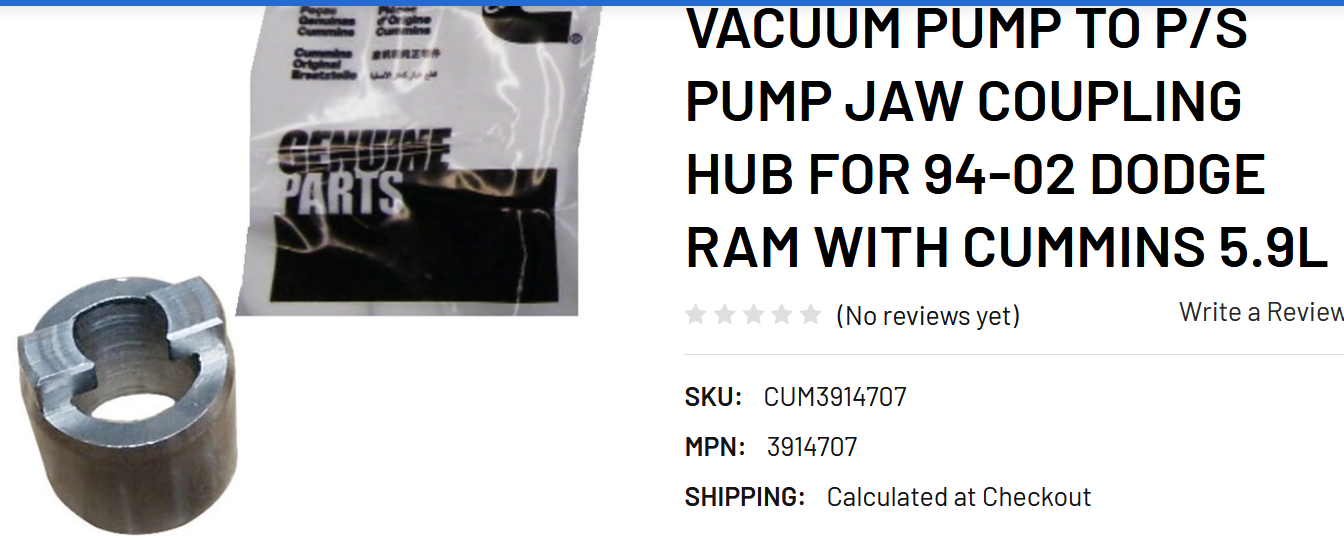
Been thinking..., Get the unit back out onto the bench (I know - you will really be looking forward to that) Remove the power steering pump. Using a depth caliper, confirm that the couplers are engaging properly. If all seems well with the measurements, then I would try this since the jaw coupling hub is pressed onto the vacuum pump shaft : Place the vacuum pump unit in a vise. Make a suitable tool that can be operated with a wrench to engage into the jaw coupling hub. Have helper hold the gear from rotating with the use of a strap wrench. Using the newly made tool and the wrench, try to rotate the coupler in the opposite direction of normal rotation to see if it slips. Use your best judgement on how much force to apply. If it slips, you have your answer. - John
-
Couplings can fail completely, or partially. If there is only a small load on the pump, a failed coupling could easily drive the pump, but the moment a larger load is applied, the coupling could begin to slip. I am not saying that this is the problem, but it can't be overlooked, especially since you mentioned at one point the you may have not had the pump fully seated during your first repair. Again, back to your first post, I am looking for you to confirm that no power steering fluid was lost during your first separation of the power steering pump from the vacuum pump. If no power steering fluid was lost, then the power steering pump would operate normally as soon as the engine was started. No bleeding of the system would have been necessary. Example of detail that I am looking for: "I removed the hoses from the pump / reservoir during the repair and lost power steering fluid" or, "I did not remove any hoses from the pump / reservoir during the repair and I did not lose any power steering fluid". - John
-
@RayNAz, thanks for providing more detail. I still need some clarification of the initial replacement of the vacuum pump. I am interpreting this to mean that the power steering pump and hydraulic system fluid were undisturbed during the replacement of the vacuum pump. Is this correct? If it is correct, then the power steering and power brakes should have been operational immediately upon startup. The fact that they didn't operate on startup indicates there is a problem with the coupling. If you did something different during the repair, please let me know. - John
-
Can you explain with more detail. It is possible that the coupler has been damaged if the pump was operated without the pump being fully seated. Also, just curious, what was the failure of the vacuum pump? Other than a leaking shaft seal, they are fairly bulletproof. - John
-
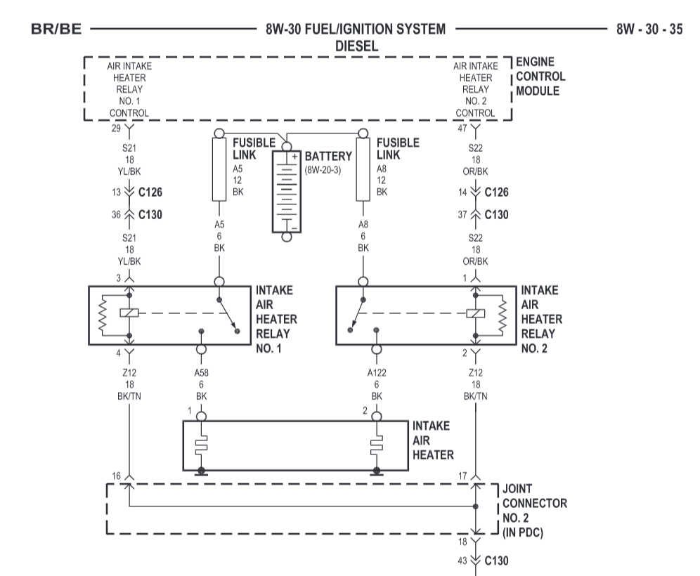
The battery referenced in the diagram is the driver side battery. Let us know what you find. - John
-
Using a test lamp, did you check all the places that should have power? I would do some testing before replacing parts. - John
-
Your father was very fortunate to have such a thoughtful and caring son. - John
-
It would be easy to check for battery voltage at the two large wire connections on the grid heater. If there is no voltage present, then the two fusible links may have failed, OR maybe you disconnected the driver side positive battery cable and forgot to reconnect the two leads to the intake heater? I know I wouldn't do anything like that..., - John
-
Did you observe the normal voltage drop while the "wait to start" light was on? I don't know what your temperatures were where you live in Kuna, Idaho were today, but here, near Baker City, the high was only 26 F. - John
-
@Mopar1973Man, @Mace is referring to a Wabasto engine block heater that is powered by DIESEL FUEL from the trucks fuel tank. It is exactly what you would want when it is - 40° and no place to plug in. - John
-
I would start with simple things first. * Check for any DTC's - write them down and clear them * Check all battery and ground connections, including cross-over cable. * Replace the fuel filter. Cut it open and check for water or any other contamination. Before removing the old filter, drain some fuel from the housing into a clean, clear container. How old are the batteries? What condition are they in? These trucks require the electrical system to be in excellent condition for reliability. - John
-
Glad to hear all is well..., - John
-
I think that is a VE distributor type fuel injection pump, but I can't answer your question about the fuel leak. I wouldn't be surprised if the seal is replaceable without removing the pump. As far as your "no oil pressure" issue, I have read (but have not experienced) that an oil pump that has not operated over a long period of time can be difficult to prime. Is your engine cranking speed fast? If not, I would address that first with a healthy battery / batteries and good electrical connections. You could crank engine with the oil filter removed to see if you are getting any oil. This may help prime the oil pump, as well. Just be sure the engine is disabled from starting. - John
-
What is the history on the '93 engine that you just installed? And I'm not being a wise guy, but has the crankcase been filled with fresh oil? - have to cover all bases. Also, while the engine was out of the truck, was the crankcase filled with oil? Maybe a plugged oil suction screen? A little more history may help. - John
-
You definitely need a fuel filter between the mechanical pump and the VP44. I believe that the last component before entering the VP44 should be a fuel filter, regardless of which fuel supply system is being used. - John
-
I didn't perform the relocation for concern of the life of the APPS. My original APPS lasted for 289,000 miles (17 years). I have just over 100,000 miles on the Timbo replacement that I now know is really a re-wired Williams Control unit (thanks to @Mace). I relocated the APPS throttle assembly because of the amount of noise the throttle transmitted into the cab - this is what @01_Cummins_4x4 is asking about. - John
-
The diagram below is from my 2002 FSM. I believe that there are 2-wire and 3-wire oil pressure switches used in the 24 valve 2nd gen trucks. As you can see, there are several components that are grounded to the ECM. The oil pressure sensor, camshaft position sensor and MAP sensor (not shown) receive 5 volt supply from the ECM. Terminal #11 on ECM (ground) goes to Splice 165. Terminal #10 on ECM (5 volt supply) goes to Splice 166. Since you don't seem to be having a problem with other sensors, I think you may have an oil pressure sensor problem. - John
-
Two things come to mind. Oil pressure is serious business. First, I would immediately check engine oil level. If it not showing on the stick, obviously add more oil and find the source of the leak. Second, If it is overfull, then check for serious fuel dilution. Low oil viscosity can result in low oil pressure. If everything checks out okay, then temporarily install a mechanical gauge to verify oil pressure under the same operating conditions. If the oil pressure is good, then replace the oil pressure sensor. - John
-
It is easy to test if there is noise being transmitted by the throttle. Set the cruise to about 65 mph and take your foot off the throttle. If there a noise, or a change in noise, or a noise that goes away (or gets worse) when you touch or rest your foot on the throttle, then you know there is engine noise being transmitted by the throttle. The noise is like a buzzy / rattly sound. Mine was there since the day I bought the truck. I just thought it was normal. Occasionally, my wife would ask me, "What is that noise?" and I would go, "Yeah, annoying, isn't it?" If this noise is occurring in your throttle, it is not necessary to re-mount the throttle assembly in the same place that I did, it just needs to be detached from the engine and mounted somewhere else. - John
-
Duly noted. There is sealant inside the heat shrink and I wrapped the wires full length with electrical tape. Just not shown in the photo. I just recently started using Deutsch connectors, so I will invest in the crimping tools. - John


