


Great work!
Unpaid Member
-
Joined
-
Last visited
-
Don't know much about delivery valves. But the idle screw needs adjusted to prevent stalling when cold and 2800rpm is because you need to upgrade the governor springs and washers.
-
This is an entirely new method of not just relocating the controller but making one from scratch. It's independent of an ECU. I made a github project with all the details https://github.com/Greatwrk/VP44-EXPLORER
-
Nice setup. I just replaced a 240v heater on a K19 cummins.
-
I might have to try that. I would need to keep a steady load on it for a few minutes to get any accuracy.
-
Thank you @Tractorman that's just what I needed. That other spec of 1.9 m/sec at 1000r/min is interesting. That may help define the slope of ramp area on the cam donut.
-
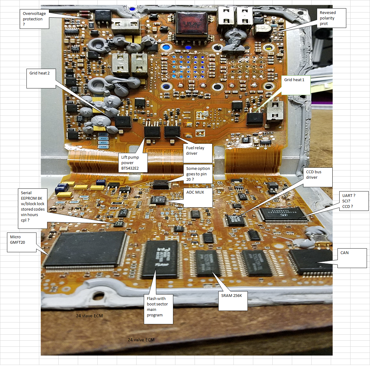
I'm working on my VP44 and ECM projects and need to know how much fuel is actually injected by the injection pump. This is so I can calculate a fuel rate in milli Liters for determining engine load and also for the overhead trip, mileage display computer. So i dug out my old VP44 core and did some measurements. I thought I would share what I found and get some confirmation or feedback. This is a SO pump with three injection plungers they are 7.3 mm diameter. The cam donut has a thickness of 10.5 mm at the maximum inward point and a thickness of 7.1 mm at the maximum outward point. So 10.5 - 7.1 = 3.4 mm of stroke. I don't have an ultra precise way to measure the stroke. I probably need to have the pump all put together for that with a special instrument and rotor head fixture, but it's probably pretty close. So 7.3 divide by 2 = 3.65 mm radius times 3.14 (pi) times 3.4 stroke = volume 39 milli liter per plunger, times 3 = 117 ml. That's the theoretical maximum injection volume without injector or line losses. So 3 injections per crankshaft revolution is 351 ml. times 1000 RPM is 351000 ml. There are 1,000,000 ml in a liter so 0.351 liters per minute at 1000 RPM. At 2849 RPM that's 1 liter / minute. The vane pump has to fill the plungers and it continues pumping to the tank while the plungers are injecting so that means it needs to pump at least twice the amount as injected. That needs 0.702 liters / minute @ 1000 RPM and 2.8 liters @ 4000 RPM. 1 liter is 0.264 gallon so 0.74 gallons per minute @ 4000 RPM. that's 44.5 gallons per hour. The lift pump would need to be 2 to 3 times that to maintain a good working pressure at the VP. Does the math seem right?
-
There had been a new design out for a few years now. It's a non contact moving magnet sensor. No wiper to wear out. Got it at O'Reilly. I wish I could find the receipt for it.
-
I decided to open source my stand alone VP44 electronics project. I started a github repository. It's far from a bolt on replacement. It's just a prototype but it has been running reliably for a couple of years now. Unfortunately, it's not a project for beginners and requires good soldering experience and there is one surface mount part on the board. The circuits have some high energy parts and requires some testing before operating. The software is not simple and has time critical routines. An in depth understanding of the MCU internal peripherals (timers, PWM) is also required. Any mistakes in assembly or coding can cause permanent damage to the fuel solenoid or speed sensor. My project explores the electrical operation of the mysterious VP44. I included some diagrams and tutorial. The mechanical operation is described on various websites so I skipped it. It may help to review some of those sites. https://github.com/Greatwrk/VP44-EXPLORER
-
Check the PCM ground to the passenger battery. The PCM is not grounded by it's case. Have you done the blow-by test with the oil cap yet. if it bounces around while setting over the hole you have bigger issues.
-
Soon. My VP44 project is being reviewed on github. It's still pretty rough. My ECU project had a couple of screw ups. So I had to cut traces and make modifications to the board. I want to update the schematic and pcb artwork before releasing. The code is going well and technically less challenging then the vp44. I already have the grids, lift pump wait to start, EEPROM save and restore, watchdog working. The idle governor will be the same as the Vp. I already have the code for the temp sensors. Called Stienhart-Heart approximation. Ckp and cmp is the same as vp project too. CAN, OBD2, SAE 1850 and error detection DTCs still to do. I've done some CAN on other stuff so it's not new to me. I have a spare instrument cluster that I can control with CCD too. I can't figure out the CCD part for the overhead mileage computer because I have no working ECU to monitor.
-
It's definitely a poor location and unnecessary. I think it was done for less noise.
-
The man I was helping had to turn in the old actuator and the core was voided if I opened it to see what was wrong and what was rebuilt on the new one. I suspect there is a potieometer inside for position sensing that wears out. I see John Deere uses a lot of oil pressure powered actuators on VGTs maybe better choice.
-
The ecu scales the fuel from tps resting to wot those values are stored. If the get corrupt then the idle changes. You could try to read the EEPROM repeatedly with arduino and get a good read then copy to a new one and solder it in. Very tricky. I'm working on a githup repository but I'm old dog and don't know what I'm doing. Lol If you have delayed WTS light then the the ecu processor is going out too.
-
The ECU is loosing it scratch pad EEPROM So that's where the tps calibration is. You can't fix without a special tool and software. I put a 1k pot on my tps signal signal to fool it and idle it down but your ecu will die soon. My VP44 project doesn't need ecu just CKP ,tps and map.
-
I think some had plug in connector on back vs. Studs and nuts.

