


Great work!
Unpaid Member
-
Joined
-
Last visited
Everything posted by Great work!
-
Thanks for the diagram, it's kinda a catch all with gas, 12 valve and 24v AT and MT all thrown together. It's confusing. I did some checking on my truck 1999 24valve auto. I have a special stand alone vp44 system. No ECM is present ( long story ). My CC light won't turn on with key on engine off. It will turn with engine running. The CC works fine without the CCD from the ECM. It disengages when shifted to neutral but light stays on. My CC works with the trans relay or the ACD relay unplugged. At C1-6 PND I get 0V in P and N. 12V in D. At C3-32 CC switch from steering wheel I get 4.7v nothing pressed. 0.93v on/off, 3.5v set. 2.86 coast. 4.18 accl. That's back probing with all 3 connections plugged in and key on. I hope this helps. I don't remember how the clutch affects the CC on a MT. It either speeds up or disengage.
-
Try doing the APPS calibration. Search this site for the procedure. It easy to do. Good battery connections and grounds are required on thees trucks. Check the ECM connector carefully for pin sockets that may have pushed back into the plastic, that can cause a bad connection.
-
So looks like the 98 must not use that pin. You are using a 98 PDC and wiring for a 12 valve? Or is that part of the 99 2500 wiring left behind? Study the pins at the connectors where the truck harness plugs into the engine harness. Also look at the old harness for the AT. Are there any extra or missing wires? Do all the pins have a mating pin in the plugs? Is there a connector that went to the AT harness that's part of the truck harness not engine harness? If so plug the old AT wiring in that went down to the tranny. I Don have a 1998 12v wiring diagram can you post a link to it?
-
It's odd the PCM has a code for the trans relay if it's a manual. Maybe wire on in temporarily. Maybe some member on here has a manual truck and can check if the relay is installed.
-
Are you using the PCM as stock for an alternator voltage regulator or do you have an external voltage regulator? The alternator field circuit and auto trans relay are both turned on when the engine RPM is running.
-
First Try checking the brake sw signal at PCM C3 pin 24. The auto tranny has a park/nuetral signal at pcm C1 pin 6 on MT truck that wire is grounded all the time. AT is grounded only in park or neutral. Maybe your PCM is setup for the AT. See if the connector has a wire and pin for that. Try cutting it if it does. Look at the old harness too. If that doesn't help then I suspect the dodge ECM for the 24 valve has a specific message on the CCD bus that the PCM is looking for to enable the CC.
-
Worn out or really big injectors can cause hunting issues usually in neutral though. The ECU can only compensate the fuel governor so far. It has some expectations for a commanded fuel rate to cause a reasonable idle then adapts a limited amount. If the engine has changed a lot from stock or is damaged/worn out the needed fuel rate can go out of the ECU expected fuel limits for idle than hunting or lope can happen. Check your fuel pressure and incorrect timing ex P0216 can cause lots of problems. Technical stuff if you want to verify APPS and ECU wiring and communication. PIN 34 is an idle valid signal from the ECM to VP. It is 12V at idle and 0V when pressed. it is pulled up to 12V in the VP on pin 4. The APPS has 2 idle outputs that are open collector that are always in opposite states. APPS pin 2 is 12v =idle, 0V = pressed. APPS pin 6 is inverted. The ECM monitors the idle signals and pot. when APPS is pressed the signals flip and is sensed by the ECM. The ECM then outputs pin 34 to change state it is sensed at VP pin 4 LGS (German) the VP then changes a byte in the CAN message going to the ECM as a cross check then The ECM increases the fuel command byte. If the pump is Hot wired, grounding pin 4 makes the engine run at a higher RPM. CAN message from VP : 22 40 8 [04 ]00 85 23 xx yy 79 13. The Byte in braces is: 0C HEX = not running 04 HEX = idle valid state (as detected via ECM pin 34 to VP pin 4) 00 HEX = above idle operation "" yy HEX is the pump RPM MSB xx HEX is the pump RPM LSB 79 13 is the fuel temp in Kelvin encoded ? BTW the harness lay out causes electrical noise on the TPS signals that shows up with automatic transmission trucks causing converter rapid locks and unlocking. When hot wired the VP uses a ball park fuel rate for idling.
-
It's probably OK after it cools off. If it's all ceramic it will be fine, they just bite even better after that. Ceramic seems to be grabby and not so great for towing.
-
Those types of problems are some of the hardest to find.
-
Keep your eye on the EGT when pulling the long hills and downshift when needed.
-
It's hard to get in there to the power steering area and even worse getting the lines undone. Mine are so rusty that they would have to be replaced too. On sheet metal covers I sometimes use a ball peen hammer on the holes so they are dimpled out ward then the bolts flatten them out. Puts more tension on the gasket.
-
Call a mobile locksmith. They can do all kinds of stuff with reprogramming and key fobs and usually for less money.
-
If you have the old seal you may be able to measure it and buy a traditional style seal to put in next to it. I had a rear seal start leaking about 5000 miles after replacement, should have used a sleeve but the crank didn't look bad.
-
You might try disconnecting pin 5 of the VP44 that line can shut it off. I have 1978 F250 mud truck. Thought about a cummins in it with a ZF5. Did yours have factory AC? do you have to run electric radiator fan? @Linux made a wiring diagram that may help https://github.com/jlaustill/fummins-data/blob/main/harnesses/00-02-cummins-engine/harness.png
-
Intentionally cause a trouble code for the PCM by disconnecting the transmission plug or the battery temperature sensor. That way you can make sure you are getting codes. Limp mode should cause a code. Also cause a fault with the ECM by disconnecting the MAP or APPS that will cause a companion code. Check your OD solenoid resistance. You said earlier that it didn't work when you bypassed the relay.
-
I think we had a prior thread on here about an IAT sensor that was overheating, melting from a leaking intake valve. Valves can be funny and rotate or walk around causing leakage. Pull the IAT and look for heating or build up and clean it. BTW, the Silverado 4.3l is an easy fix. Ozone builds up in the distributor cap. Just drill some vent holes in the distributor base.
-
Well that's a lot of work ahead. What's better about a one piece drive shaft?
-
I measure about 10mm of stroke on my standard VP. I don't have any way to measure it exactly. I've been quietly working on a new project called ECM Explorer. I have PCBs already and connectors. But I have been designing a case and mounting plate for it. I'm using FreeCad, Slic3r and a 3D printer and I have never done anything like it. It has been a real learning experience. The mount will be Lazer cut aluminum probable Xometry or Send cut Send. I'll be happy to have all my guages working again. The code is a basket case of functions from other projects right now and I still need to stuff a board and get any bugs out of it. I'm going to have to rig up my VP with switches to cut back and forth and parallel run with my own and stock PSG so I can finish decoding the protocol between it and the ECU. I have no Original ECU that works that makes things a little tricky. I did record some sessions a long time ago as the ECM was starting to die. When I get things farther along I'm going to open source it on GitHub, that will be another learning experience.
-
Try tweeking the relay pins and sockets. Maybe just bad connections
-
Any codes? Is charging system working (NA for external regulator conversions). Is AC clutch working, if worked previously? Swap relay with another. Starter only works in park and neutral and not in drive? Output speed sensor causes stuck in first symptoms not usually limp. TC solenoid and OD solenoid should have good resistance readings both are similar. Speedometer works? Internal temperature sensor resistance reading? Clean re-seat all connectors above engine by brake booster.
-
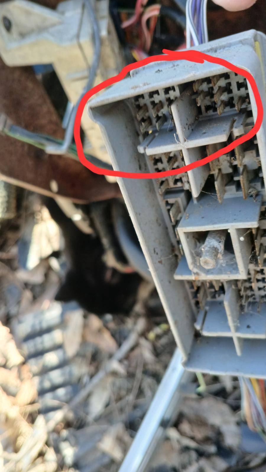
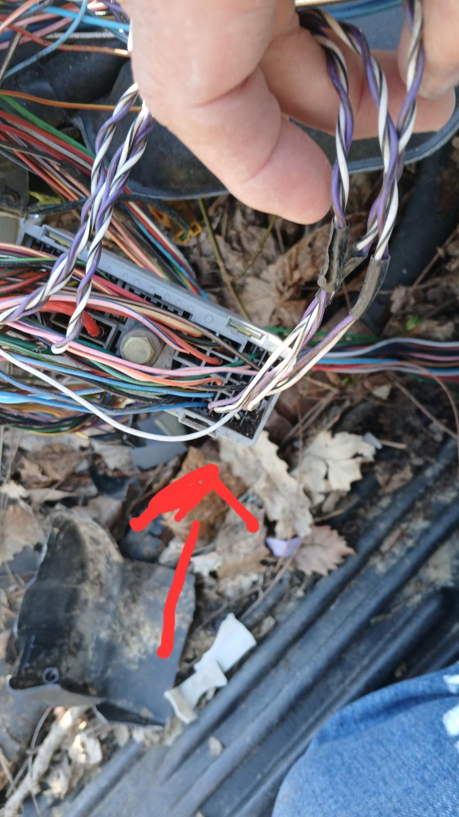
My diagram shows pcm 28 to ABS 10 for CCD- . Pcm 30 to ABS 3 for CCD+. Double check and verify your ohm meter and test leads are working by touching them together. Open up the large bulkhead connector and check the 3 twisted pairs of wires. Look closely at both mating connectors for bent pins or spread sockets. Lightly tug each wire and make sure they are locked in to the plastic good. See photo.
-
Never tried them. I replaced mine with stock rated springs from a shop cost a lot less but rides terrible. To get a soft ride you probably have to take some leafs out so it's wimpy and then use blocks to get your ride height. Then add air bags so you can tow. But air suspension sucks, too many problems.
-
Get some stuff called No Ox ID. It works great and it's electrically conductive. I use it all the time.
-
Open up the harness over the engine and follow the ccd wires. On a 24valve they have 3way t that goes to ECM , not sure about yours.
-
So after all that it still doesn't work? Check for good continuity on the ccd wires from the PCM to ABS and then check continuity from ABS to cluster.
