
APPS Sensor Replacement Procedure
Description
The Accelerator Pedal Position Sensor (APPS sensor) assembly is located at the top-left-front of the engine (Fig. 4). A plastic cover is used to cover the assembly. The actual sensor is located behind its mounting bracket (Fig. 5).
Operation
The Accelerator Pedal Position Sensor (APPS Sensor) is a linear potentiometer. It provides the Engine Control Module (ECM) with a DC voltage signal proportional to the angle, or position of the accelerator pedal. In previous model years, this part was known as the Throttle Position Sensor (TPS). Diesel engines used in previous model years used a mechanical cable between the accelerator pedal and the TPS lever. Linkage and bellcranks between the TPS cable lever and the fuel injection pump were also used. Although the cable has been retained with the Accelerator Pedal Position Sensor (APPS sensor), the linkage and bellcrank between the cable lever and the fuel injection pump are no longer used. The Accelerator Pedal Position Sensor (APPS Sensor) is serviced (replaced) as one assembly including the lever, brackets, and sensor. The Accelerator Pedal Position Sensor (APPS Sensor) is calibrated and permanently positioned to its mounting bracket.
Removal
The Accelerator Pedal Position Sensor (APPS Sensor) is serviced (replaced) as one assembly including the lever, brackets, and sensor. TheAccelerator Pedal Position Sensor (APPS) is calibrated to its mounting bracket. The Accelerator Pedal Position Sensor (APPS Sensor) assembly is located at the left front of the engine below plastic cable/lever/linkage cover (Fig. 6).
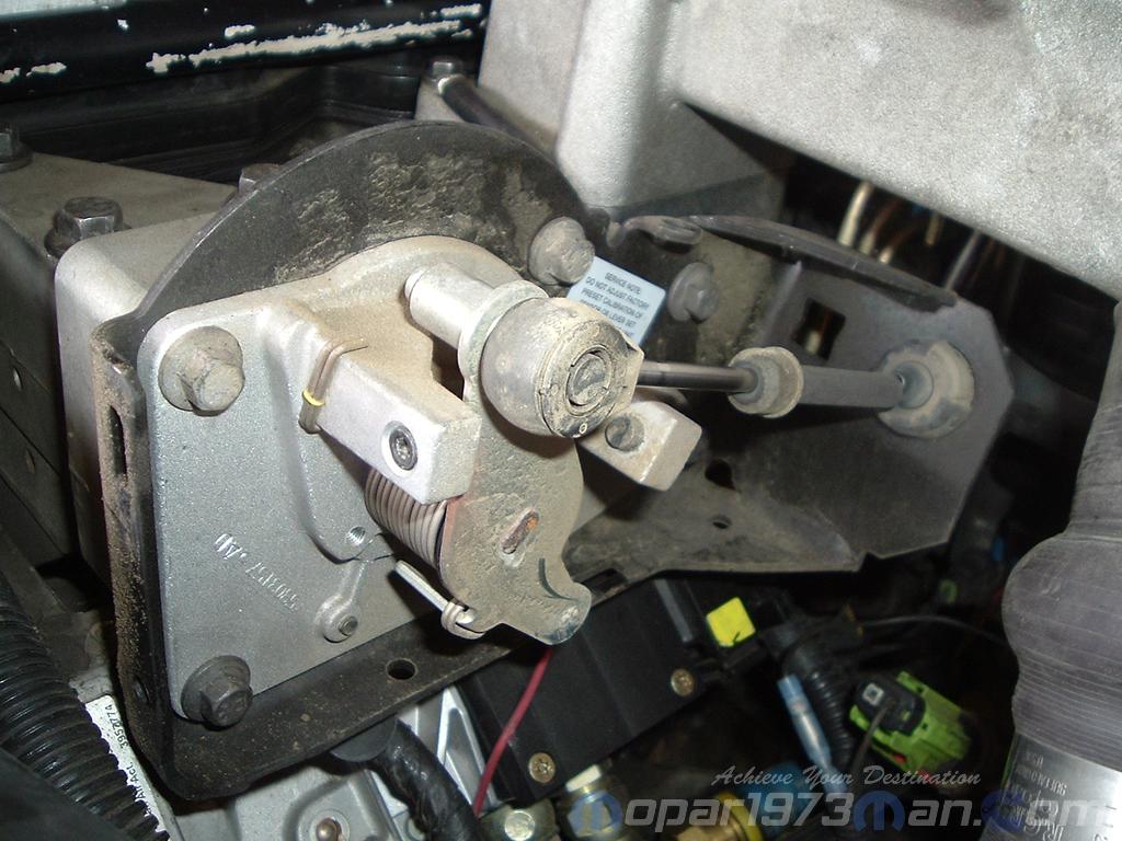
Front with cover removed
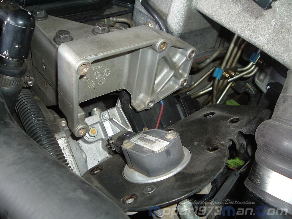
Rear of APPS sensor
- Disconnect both negative battery cables at both batteries.
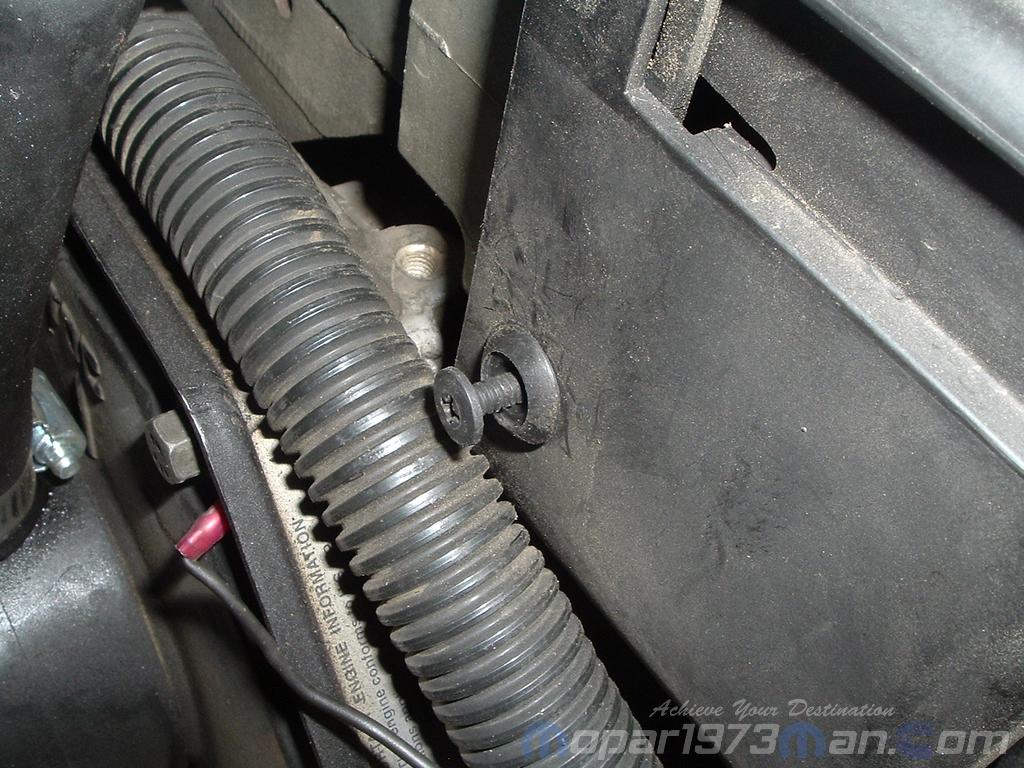
- Remove cable cover. Cable cover is attached with 2 Phillips screws, 2 plastic retention clips, and 2 push tabs. Remove 2 Phillips screws and carefully pry out 2 retention clips. After clip removal, push rearward on front tab, and upward on the lower tab for cover removal.
- Using finger pressure only, disconnect end of speed control servo cable from throttle lever pin by pulling forward on connector while holding lever rearward.DO NOT try to pull the connector off perpendicular to lever pin. The connector will be broken.
- Using two small screwdrivers, pry throttle cable connector socket from throttle lever ball. Be very careful not to bend throttle lever arm.
- Disconnect transmission control cable at lever arm (if equipped). Refer to 21, Transmission.
- Squeeze pinch tabs on speed control cable and pull cable rearward to remove from cable mounting bracket.
- Squeeze pinch tabs on the throttle cable and pull cable rearward to remove from cable mounting bracket.
- If equipped with an automatic transmission, refer to 21, Transmission for transmission control cable removal procedures.
- Disconnect wiring harness clips at the bottom of the bracket.
- Remove 6 mounting bolts and partially remove Accelerator Pedal Position Sensor (APPS sensor) assembly from the engine. After the assembly is partially removed, disconnect the electrical connector from the bottom of the sensor by pushing on connector tab.
- Remove Accelerator Pedal Position Sensor (APPS sensor) assembly from the engine.
Installation
The Accelerator Pedal Position Sensor (APPS sensor) is serviced (replaced) as one assembly including the lever, brackets, and sensor. The Accelerator Pedal Position Sensor (APPS sensor) is calibrated to its mounting bracket. The Accelerator Pedal Position Sensor (APPS Sensor) assembly is located at the left front of the engine below plastic cable/lever/linkage cover (Fig. 6).
- Snap electrical connector into the bottom of the sensor.
- Position Accelerator Pedal Position Sensor (APPS Sensor) assembly to the engine and install 6 bolts. Tighten bolts to 12 N·m (105 in. lbs.) torque.
- Connect wiring harness clip (Fig. 8) at the bottom of the bracket.
- If equipped with an automatic transmission, refer to Group 21, Transmission for transmission control cable installation procedures.
- Install speed control cable into the mounting bracket. Be sure pinch tabs (Fig. 7) have secured cable.
- Install throttle cable into the mounting bracket. Be sure pinch tabs (Fig. 7) have secured cable.
- Connect throttle cable at the lever (snaps on).
- Connect speed control cable to the lever by pushing cable connector rearward onto lever pin while holding lever forward.
- Install cable cover.
- Connect both negative battery cables to both batteries.
ECM & APPS Calibration
WARNING! Any time the batteries are disconnected, batteries ran dead, ECM disconnected, APPS disconnected, APPS replaced the APPS calibration procedure MUST be done again to reset the APPS idle and WOT limits. If the calibration is not done error codes and other issues must occur.
Disconnect the batteries and leave disconnected for at least 30 minutes. Now reconnect the batteries.
Turn the key to ON position. Without starting the engine, slowly press throttle pedal to the floor and then slowly release. This step must be done (one time) to ensure accelerator pedal position sensor calibration has been learned by ECM. If not done, possible DTC’s may be set.