
PCM Ground Splice Repair
It's not hard and took very little time to do.
NOTE: Do this after the other modifications have been done or you will lose the ECM, VP and grid heater grounds.
You need:
2 10-12 gauge butt connectors
2 1/4 heat shrink tube 2" long
Rosin core solder
140 watt solder gun (Weller) or small butane torch
1 roll of electrical tape
Razer knife
Wire cutters
Wire striper
Remove the air cleaner housing this will open up the whole area to work in.
No need to disconnect the batteries, just unplug the gray connector at the ground wires of the right (AUX) battery. The other gray connector may have already been disconnected when the ground wires were relocated to the back of the timing cover if a W-T .
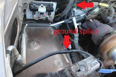
Disconnect the 3 plugs at the PCM
|
|
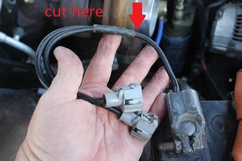
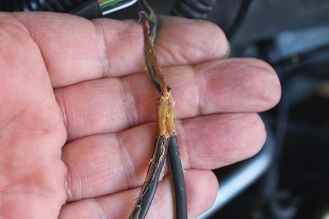
Cut and strip the 8 gauge wire then cut the connector off the 10 gauge wire and strip it back to fit the butt connector.
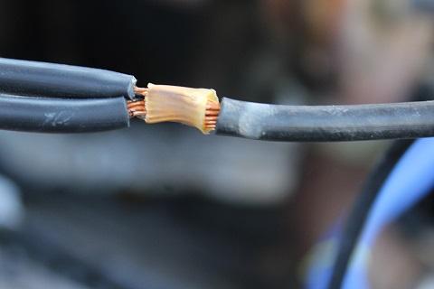
This is the connection with the cove off. This is splice #S109 that the grounds for the ECM, PCM, VP44, grid heater relay and data link connector.
|
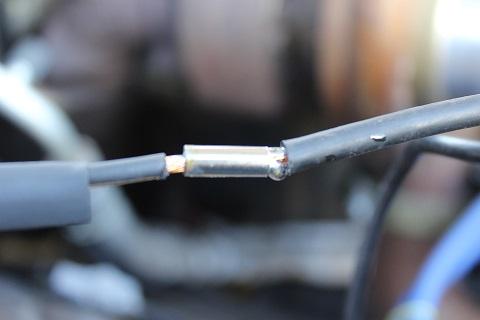
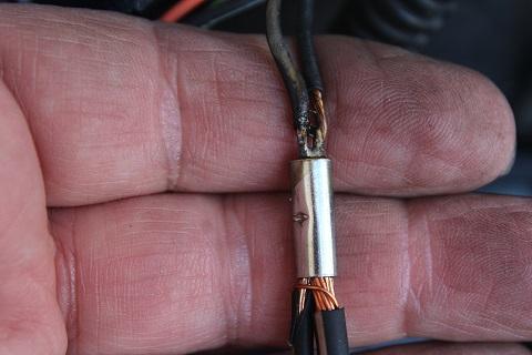
Slide the heat shrink on to the wire were it won't be affected by the heat of soldering. Remove any plastic covering on the butt connector; insert the wires into the connector and solder. Let cool then cove with the heat shrink.
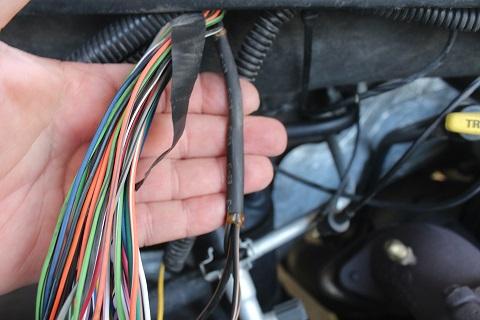
At the PCM find the two 14 gauge black with tan stripe wires. They go up into the split wire cover about 10" that's where you'll find splice #S126
There are two 14 gauge black with tan strip wires coming down to the connector. One is the ground for the data link connector and the other is not used.
Repeat the cut, strip and solder process as above.
When done it should look like this.
There are no warranties implied or expressed.
Written by: J. Daniel Martin AKA IBMobile 2/29/2020 |
-
 3
3
-
 3
3