
Ok I know several members have done this mod and said it was easy. It sure is easy. It takes about 2 hours from start to finish to complete this project. You'll need the terminal lugs and the metric bolt that @W-T specifies in his article.
First thing disconnect your batteries. I unhooked the two negative leads.
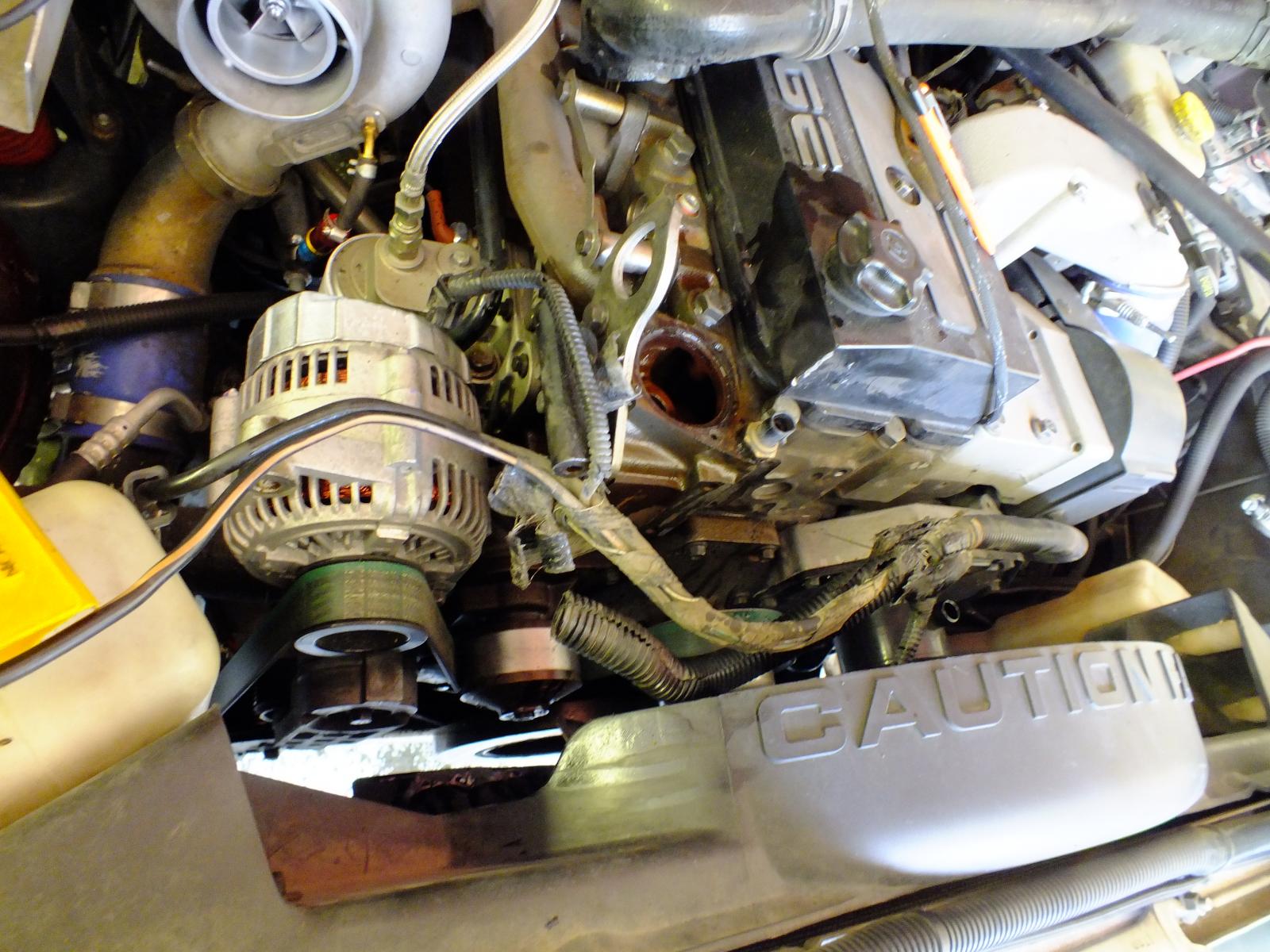
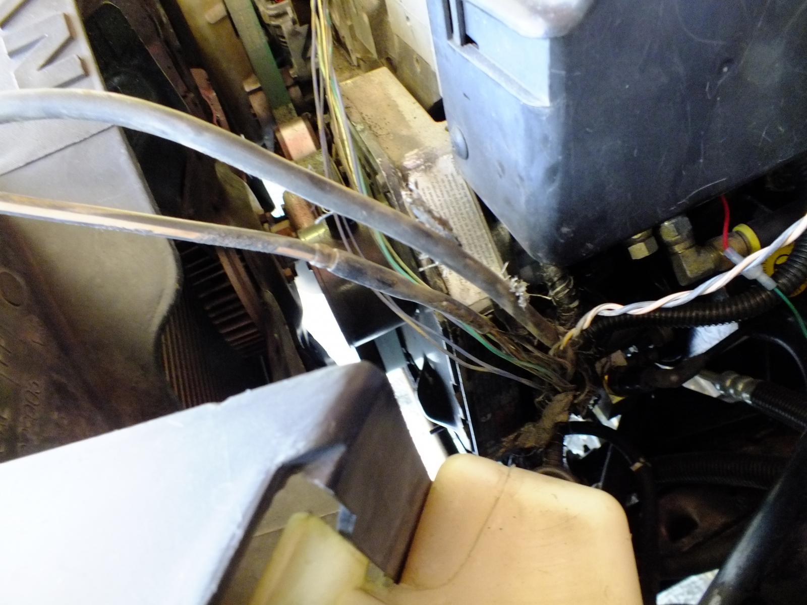
You need to gain access to the loom going across the front of the engine. So you'll need to remove the upper alternator bracket and the the two loom holders on the front of the block. I did this during my coolant flush project so my upper hose and thermostat are removed. If you have my crankcase vent that will need to be removed as well.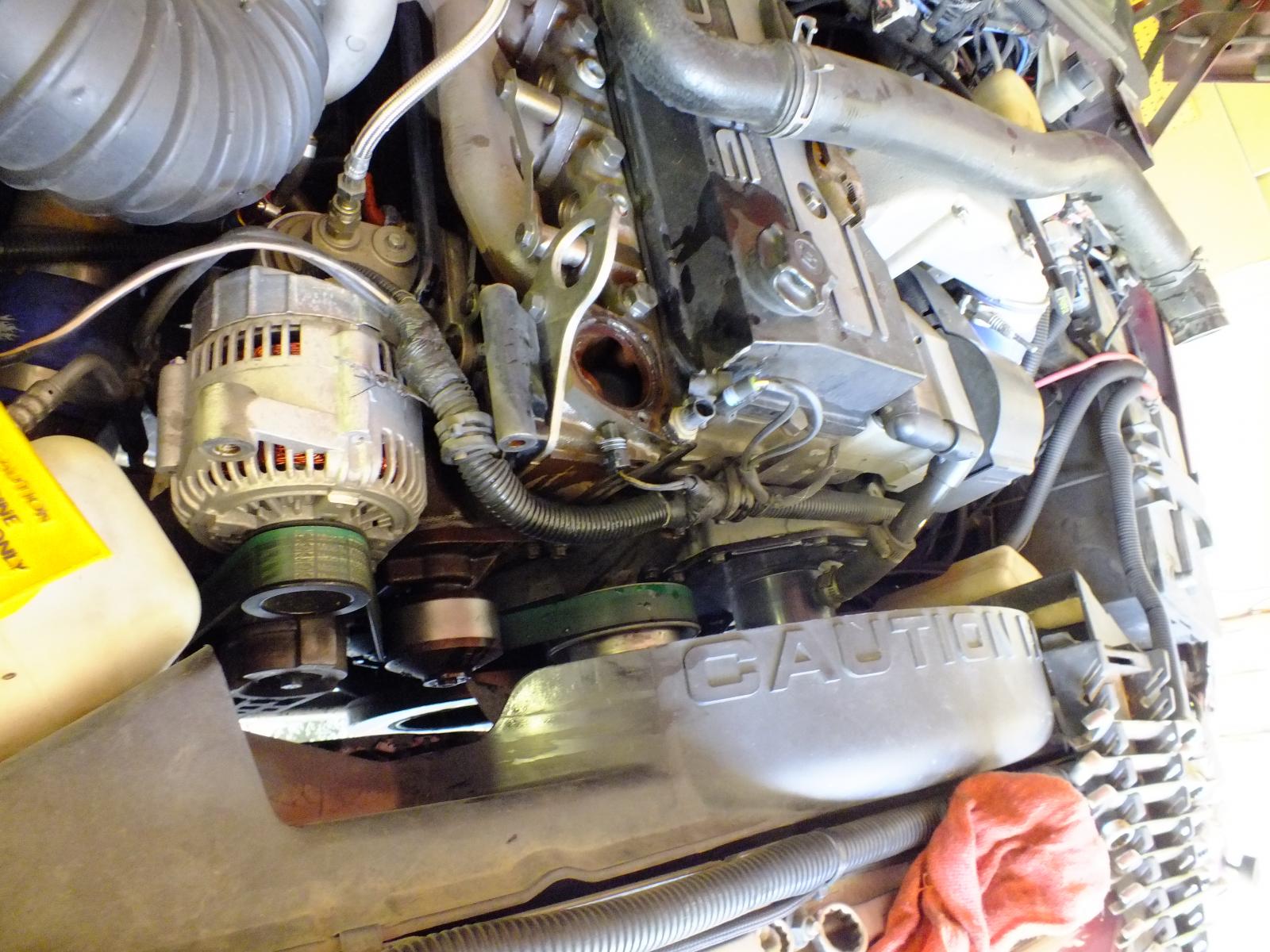
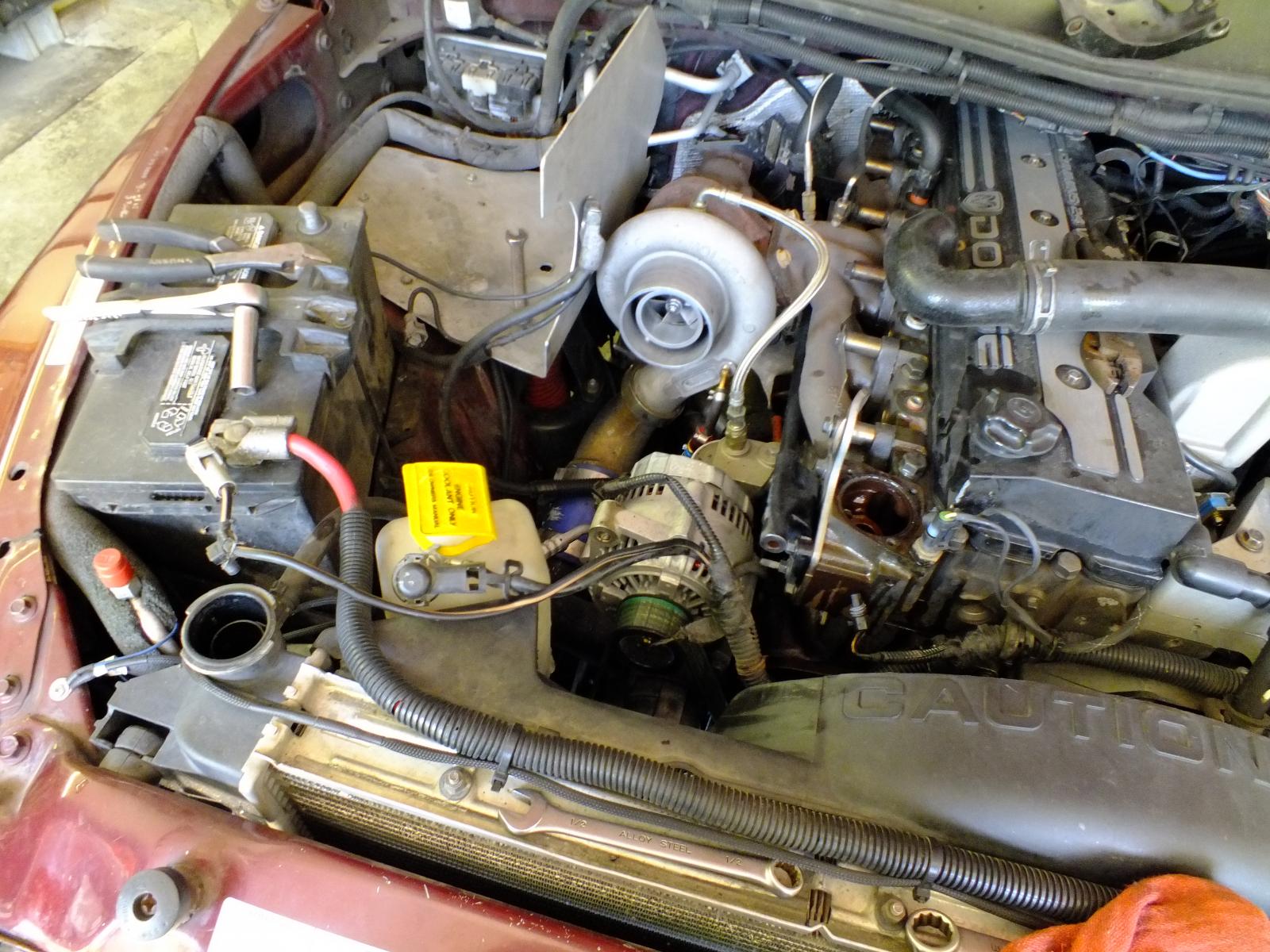
Now I started at the battery and the alternator and started unhooking the wiring from these devices bring it forward.
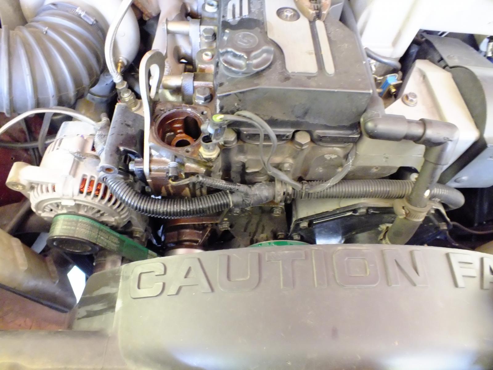
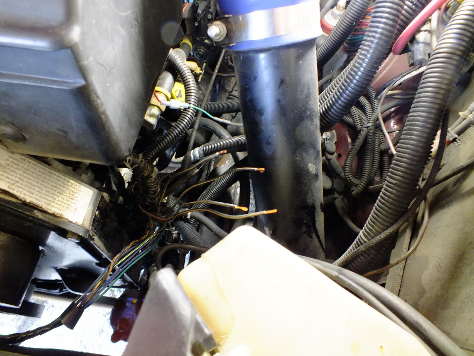
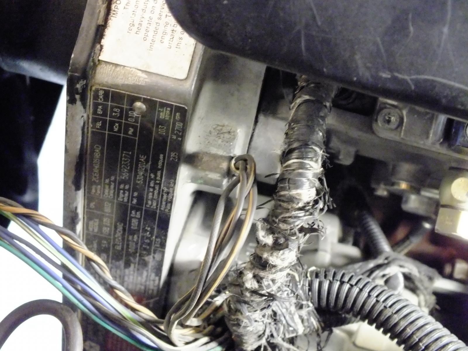
Now you start working on getting the split loom off the wiring. Start at the tape with a small exacto knife or razor blade and carefully split the tape to release the plastic split loom cover. Carefully remove it. I found out mine was brittle after all the years of engine heat. Once you remove all that slpit loom you can again split the spiral tape holding the loom together.
Now you show be able to have both the ground lead and the alternator charge lead loose now. I will admit the alternator lead took a bit of work to release at the knot of tape on mine where it breaks out of the loom heading for the PDC. Just take your time with your razor blade and your get it released. You can clearly see the splice of the ground just like @W-T mentions in his article.
Once you get the alternator lead out in one piece. Then the ground lead I used a pair of wire dikes and cut the ground right at the end of the splice. Now the alternator lead I reused the wire since it was in excellent condition. I mocked up the alternator lead by hooking it back up to the alternator like it should be and gave it a nice loop of slack then cut it to meet the positive battery terminal.
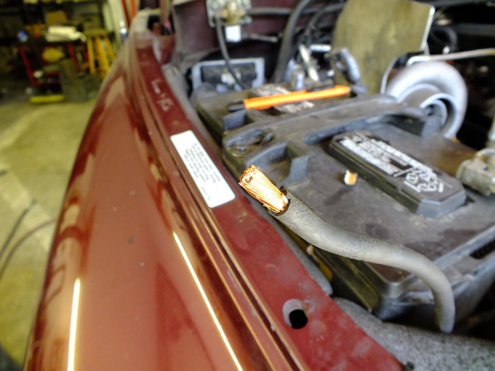
On my terminal lugs, I took a hacksaw and scored the plastic collars and peeled them off for soldering. Then slipped the lug on and used a propane torch with the low flame and soldered the lugs right on to the wire. Good sold weld and this will seal the wire from future rot from battery acid and vapors.
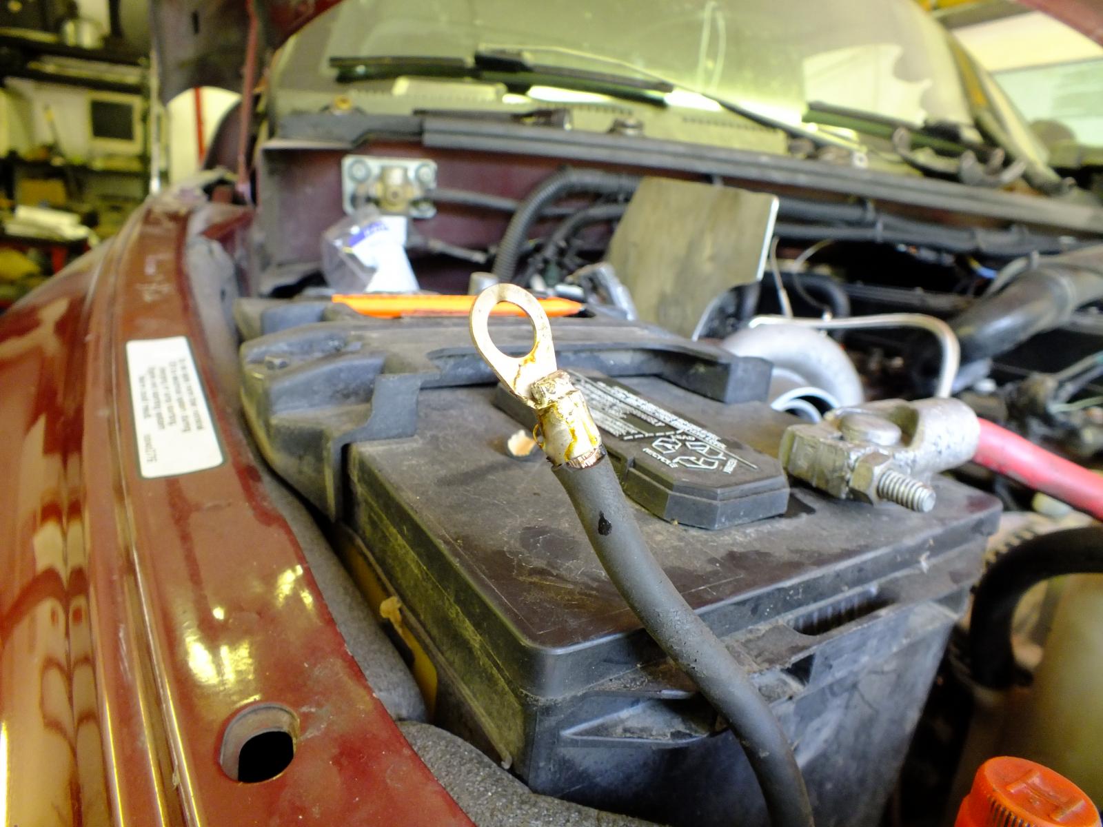
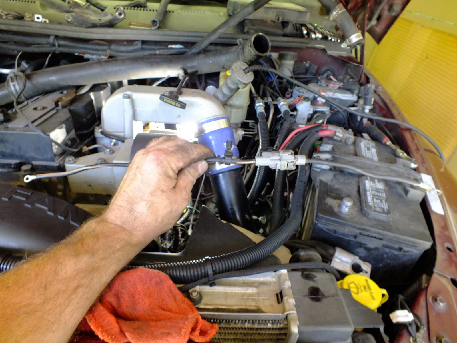
This is the completed alternator connection now. All I did was grab an old nut and stacked on the battery terminal.
Now we are going to do the ground side. Now trim back the old splice and free the ends of the wires. Now strip back the wire so you can fit the wires into a lug. Again I did the same thing I took the hacksaw scored the plastic collar and peeled it off the lug and then slipped it on the wires and prepped it for soldering.
Again just slipped the lug on the wires and low flame with a propane torch I soldered the lug to the wires.
Now I cut the old plug off the splice on the passenger side ground and then trimmed the length of the wire with the plug so it would reach between the driver side battery and the gear case. Same again I peeled the plastic collar and slipped the lugs on and soldered with low flame propane torch.
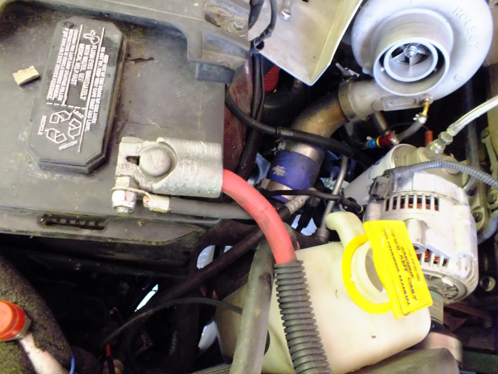
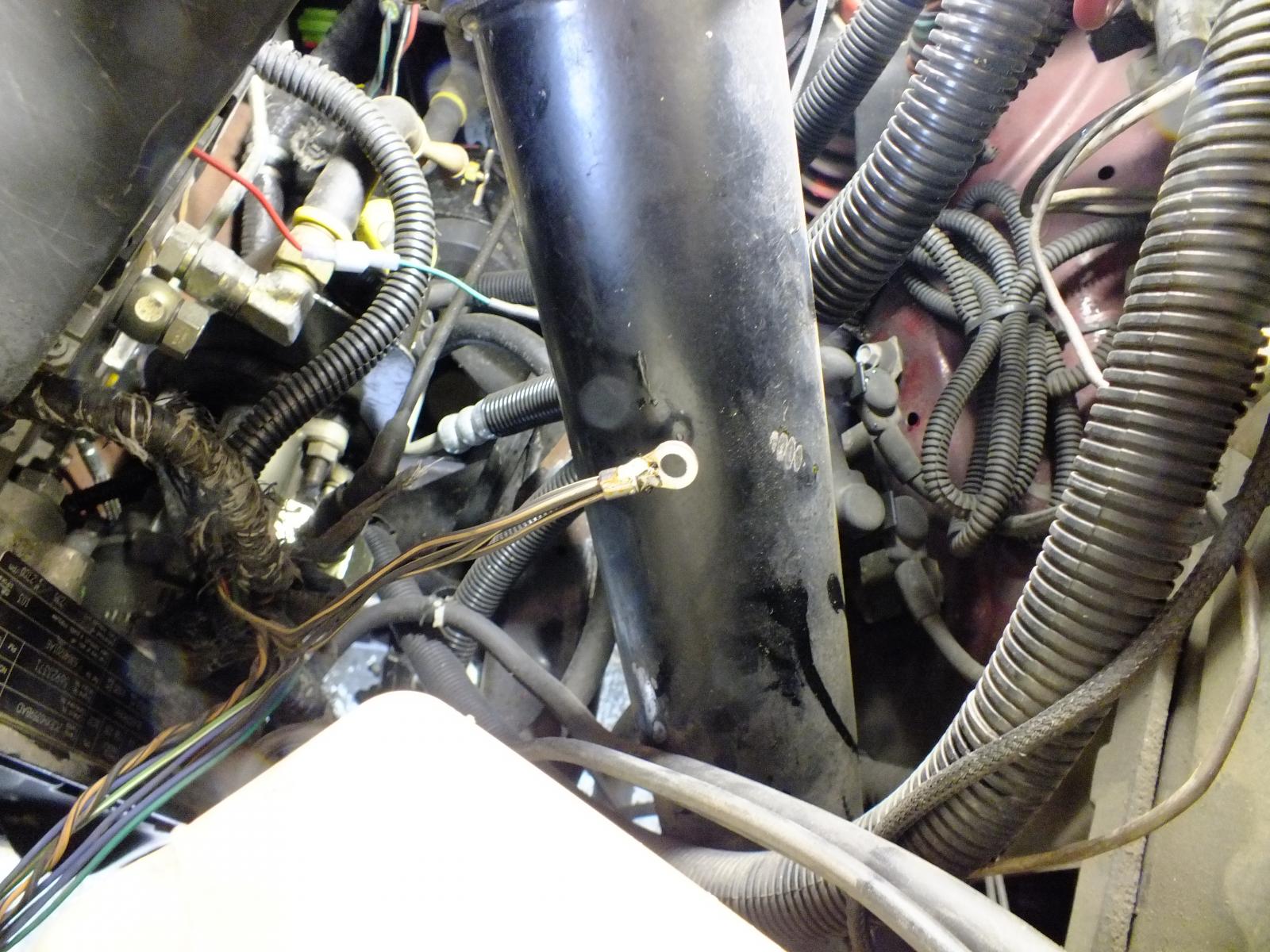
This gives you an idea where the wires go. Take your metric bolt and attach the ground wires to the case. Then the ground cable to the negative battery terminal on the driver side.
Beyond this is just clean up. Now you need to tape up your loom again. I'm going to replace my split loom with a smaller size being the old loom was brittle and was breaking during removal. The only thing that should run across the front of the engine now should be the ECT sensor which is a twisted pair. The A/C compressor, A/C high-pressure switch, and the alternator field lead.
Before AC noise level was 0.038 AC volts now after the mod its dropped to 0.015 AC volts (or 15mV AC).
About the parallel cables...
There is lot of folks being told they NEED the parallel the positive and negative cables. To test if you need that or not. Take a good quality DVM meter capable of DC mV scale. Now place a Black probe on the battery terminal and the red probe on the block (clean metal). Typically I see 3mV (0.003 volts) after doing the other part of the ground wire mod. Now take a set of jumper cables and go from the negative post to negative post. Also check the AC noise voltage with the jumper cable hooked up if there is no real change then you do not require the parallel cables. If the voltage drop is the same with the jump cables then you do not require the parallel cables because there are ZERO improvements. You can do this on the positive side as well. If there is a voltage change my first thought is to replace the BAD cables first before paralleling on a bad cable. All you do is covering up a bad connection. Adding the extra cables will not improve anything if it's not changing the voltage drop from point to point.
Addon: Protection fuse or fusible link
Some members are suggesting to install a fusible link or fuse of the same size at 140 Amps on the charge lead as a protection method. Just in case for some reason the diode bridge happens to short the positive side to the ground and doesn't start an engine fire. As for the size of the fusible link is still unknown as of yet. The factory is 140 amp fuse. The fusible link would be better suited than a fuse.
I've found a few trucks that is incapable of doing a circuit breaker because of mystery loads and causing the breaker to trip prematurely. Fuse will solve this problem but make sure to carry an extra fuse.
Addon: Resettable Circuit Breaker
I picked up an inexpensive 150A circuit breaker from Amazon. The breaker does the job but over time the breaker will get weak and trip prematurely. I still favor the circuit breaker over a fuse for the alternator protection. Fuses you might go through several and be left high and dry without a spare and unable to drive home. Make sure you buy plenty of spare fuses if you go that route. Even with my backcountry travels I still trust the circuit breaker better.
-
 11
11
-
 7
7