

- Replies 80
- Views 12.3k
- Created
- Last Reply
Top Posters In This Topic
-
ducktape11 41 posts
-
Mopar1973Man 18 posts
-
Tractorman 14 posts
-
IBMobile 6 posts


Most Popular Posts
-
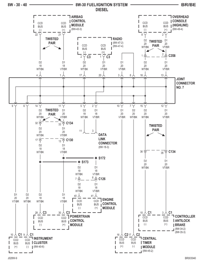
I think you could temporarialy wire in a LED lamp to the OR/BK wire from Connector #2, terminal #11 of the PCM. Wire the other side of the LED to ground. The lamp would be on all of the time after t
-
My truck's 3-4 upshift @ ~45mph with light throttle and stock 4:10 diff.
-
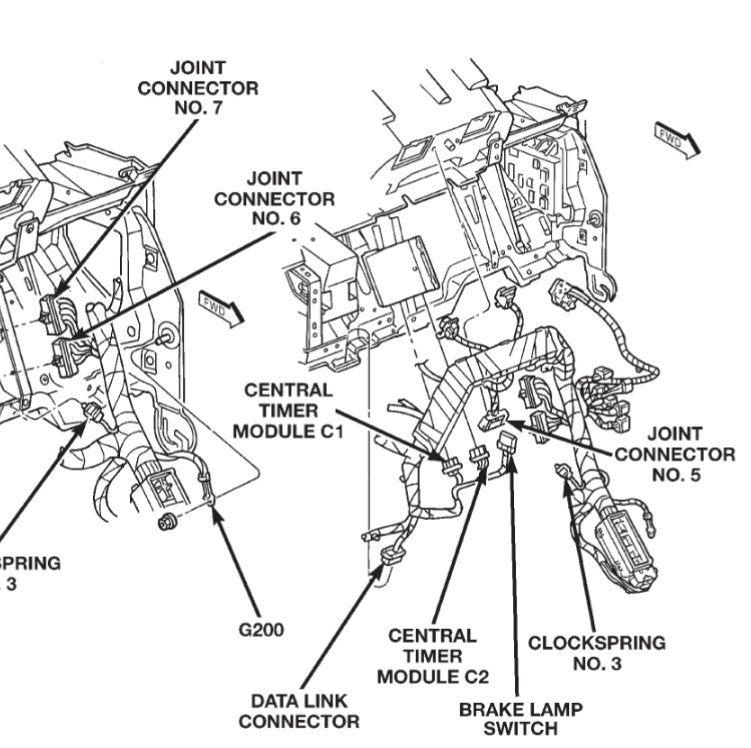
I suspect that you may have a poor body to frame ground, or poor body to battery ground. Since the blower motor switch grounding and the data link grounding are in the body ground circuit, a poor bod
So I've come to the almighty moparman forums seeking help on an unusual issue I'm having. My truck is heavily modified by the previous owner and I'm constantly having to fix one thing or another and chase things.
So I have 2 issues now 1 of which I believe I know the issue but don't know a good fix.
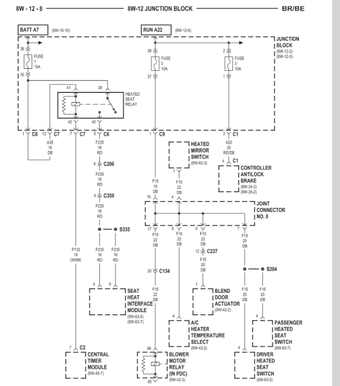
First issue is I get trans limp mode and a P1689 with no buss on the CCD when turning on the HVAC blower at any speed. Once turned off it goes back to normal. I have taken the ground off for the HVAC controls and the no buss issue also happens without the blower motor running only in face vents or floor vents position.
Looking at wiring diagrams I can't tell where any of the HVAC would cross with CCD modules.
Second issue I'm having is TCC lockup. I have increased line pressures and a DTT box to decrease the voltage to 4.5v all the time. It engages sometimes but not others and the only way I can tell is just by RPM at 60mph. It's 1 tick below 2000rpm with 4.10 ratio rear. I believe maybe the DTT box is bad or the line pressures are too high? What is the TCC lock up algorithm? Sometimes if I left off the pedal and slowly accelerate it will be locked. It's easier to tell if it's locked when I'm towing which is what I use the truck for.
Thank you for any help! I'll provide any info y'all need and hopefully I can get this all figured out!
Edit* forgot to mention I have done the following things to try to fix both issues.
PCM grounded to pass side battery negative
W-T mod
New batteries and alternator
Disconnected a/c relay and compressor( didn't fix so I guess it's not in the a/c circuit)
Edited by ducktape11
Added info