Mopar1973Man
Owner
-
Joined
-
Last visited
Everything posted by Mopar1973Man
-
You are in Central time, so I'll hit you up at 5 pm our time here in Idaho (Mountain time)
-
Another member here told me some information about the CPAP software he was using for his CPAP device. He referred to a program called Sleepy Head. I did a quick search on Google and found OSCAR. OSCAR does the same task of showing off all the medical data from your CPAP device. I wanted to share this knowledge with other Linux Users.
-
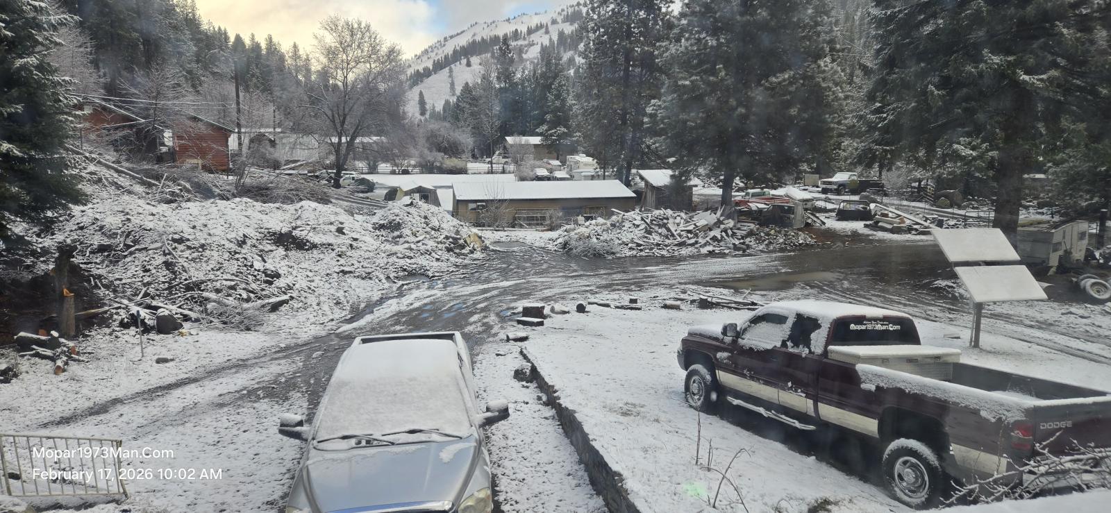
With how the wintertime is going for us up here. I pulled Thor back online to see if I can get more done. @Tweety Bird and I ran Thor to Lewiston, Idaho, for our shopping trip for chow and supplies. Thor is actually running quite well when fully warmed up. Even with a weak set of rings yet, Thor fires up every cold morning with white smoke and offbeat idle till those rings warm up some. Thor has been a comfortable truck to run, but there is add ons I'm looking at doing. First, I'm going to look into gauges, which will include rail pressure and lift pump pressure. I already have boost and pyrometer installed. I know there is no more power or tuner being added till I can get the engine rebuilt. I know the added power could break the rings, possibly. I'm going to look into replacing the driver's seat cushion and seat skin. Much as I'd love to just jump out and work on Thor, I'm held up for the weather, which is currently snowing here today. I've got no shop, so working in the snow is not happening. Another thing is the banner decal I have for the rear window too. Without a doubt, Thor has the potential to be a great truck in time. Just between my cancer, body limitations, and the weather being my shop is gon, it's impossible right now to get very much done. I'm working on things on the server, little at a time, trying to add things and make pages load faster than ever, since I'm opting for breaking up the website into divisions, and now pages are not super long like before.
-
Here is a wonderful display of why I enjoy Ubuntu... Yeah, I'm a CPAP user, and would it be nice to review your own CPAP data here is a good program that worked first try with my Resmed 11 Airsense CPAP. https://www.sleepfiles.com/OSCAR/ They have both Debian and Ubuntu versions.
-
I can teach...
-
I've now seen it all. There is a younger group of people in the Goth community saying you have to be of "democratic aligned" to be Goth/Emo/Alt. I will be the first to say "No!!!" I will NOT support democrat values, being that I'm number one, I'm an American Citizen, and watching my tax dollars go for Ukraine, Minnesota fraud, USAID fraud, the list goes on and on. How about Social Security? Yeah, I'm now disabled, but why are there so many illegal aliens on Social Security in Minnesota? Never contributed anything. Then, as time goes on the more fraud, waste, and abuse of power by democrats are being uncovered. Just like the Green New Deal was crushing the diesel community with all the rules and regulations affecting the very business I've built. Then, to find out it was the Green New Scam of the Democrats for more taxation for Climate change. Sorry, I'm not on the Democrat side, nor do I want you to follow me if you have Democrat values. I will not be forced into doing anything! After the entire fact, I was not supposed to be here. I was supposed to be dead from my bladder cancer. I survived and for a reason! I'm going to live my life without rules or anything that is going to restrict me in what I enjoy, which is my makeup artistry that includes Goth/Emo/Alt designs. This means I will not be forced to listen to anicent music artist like Depeche Mode. Sorry, there is a whole new stream of music out there, and music is not the only thing made goth what it is. Then, just like politics, I will not be forced to follow a democrat when I know full well they are the cause of the economy and the downfall of America as today. Which the democrat policies impacted my business, as I was a diesel mechanic. Democrats are built on lies and on top of lies.
-
No kidding, you had a helluva ride yourself. Walking up to The Devil himself, slapping him in the face, and walking off, back to your life. It's really weird for me, because I've got the bag on me, then at night I hook up another 2L bag so I can sleep the entire night. To top it off, I wound up finding out I'm a sleep apnea patient now, too. So mask on the face and tube to my bag and hope like hell you don't pull the tube off the bag. (Yes, I've had several wake-up calls in the middle of the night.) Yeah its no fun ride, yeah I'm now listed as disabled as well because of my bladder cancer, Chronic Kidney Disease 3a, ostomy bag, L3 & L4 in my back, etc. Absolutely... How about this evening, I call you (using profile info). Get to meet @Tweety Bird also...
-
Yes. About 10 to 20 times. Typically, bad load to engine speed issues. Like idling with the grid heaters banging away at the batteries. Weak batteries will make the breaker pop.
-
-
-
-
-
No. Just make sure to carry extra fuses. Not just one either. I opted for the resettable circuit breaker and easy to just toggle the reset arm.
-
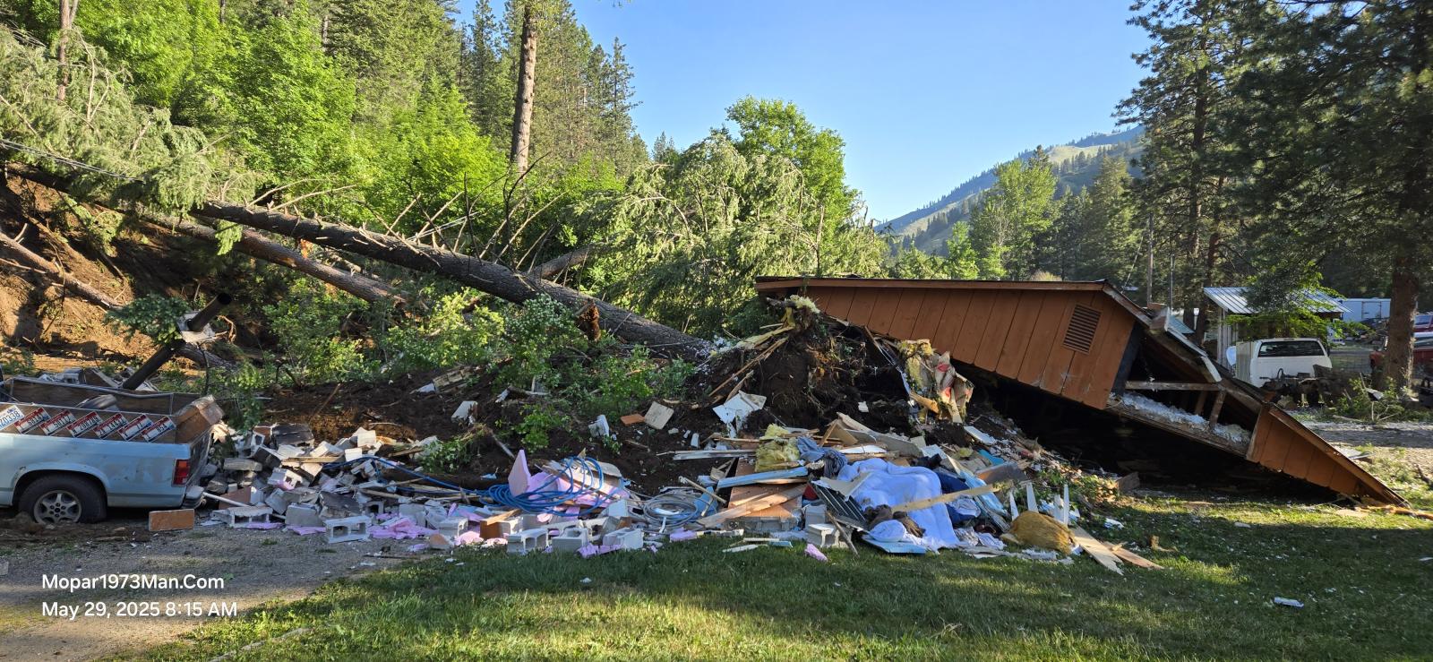
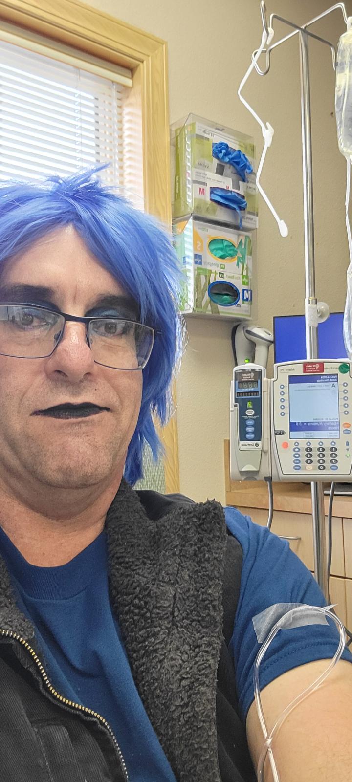
Your commander and chief has now survived bladder cancer twice now. I ended up losing my bladder for life and now have an ostomy bag. Titanium is the makeup artistry I started during my cancer that I wasn't supposed to survive. Then during my cancer I met my wife in a medical waiting room twice and we got married 11/25/25. https://mopar1973man.com/gallery/category/11-titanium/ Then last year May 29 I lost my entire shop to a massive landslide that destroyed the building. Shop no longer. Hard to work on my truck now in the mud of the yard with medical limitations that prevent me from doing as I did years ago. I got to finish my gallery move for some of the other photos. My life was permanently altered, and I can no longer go back to the things I enjoyed for so long. The makeup artistry keeps me safe by restricting me from just jumping in to rescue. I have a 40-pound weight limit for the rest of my life, as my L3 and L4 in my back are shot, and then the ostomy bag is a hernia risk for me. Everything I thought I was planning on doing is now forever changed by my cancer. There is a reason my appearance is forever changed, being I got to deal with my ostomy bag, leaks, accidental leaks, etc. My kidneys are damaged, my right kidney is only 17% remaining and my left is 82% remaining. Chemo done its damage to me. I have to be careful of UTI because it could kill me. I can't be in a dirty world and even touch my bag or drain valve. I still deal with phantom bladder, where it feels like I have to go really bad, but there is nothing there. Yea,h so Titanium was my creation to hide my bald head and my sick appearance from the chemo. Moving forward @Tweety Bird my wife and I are trying to keep the website going with what I've got left. Like today its snowing out in the yard, and since my shop is gone, I'll be waiting till the weather changes and dries up so I can work in the dirt. Oh update there is a weather tower here and you can see the weather in the Mopar1973Man Menu.
-
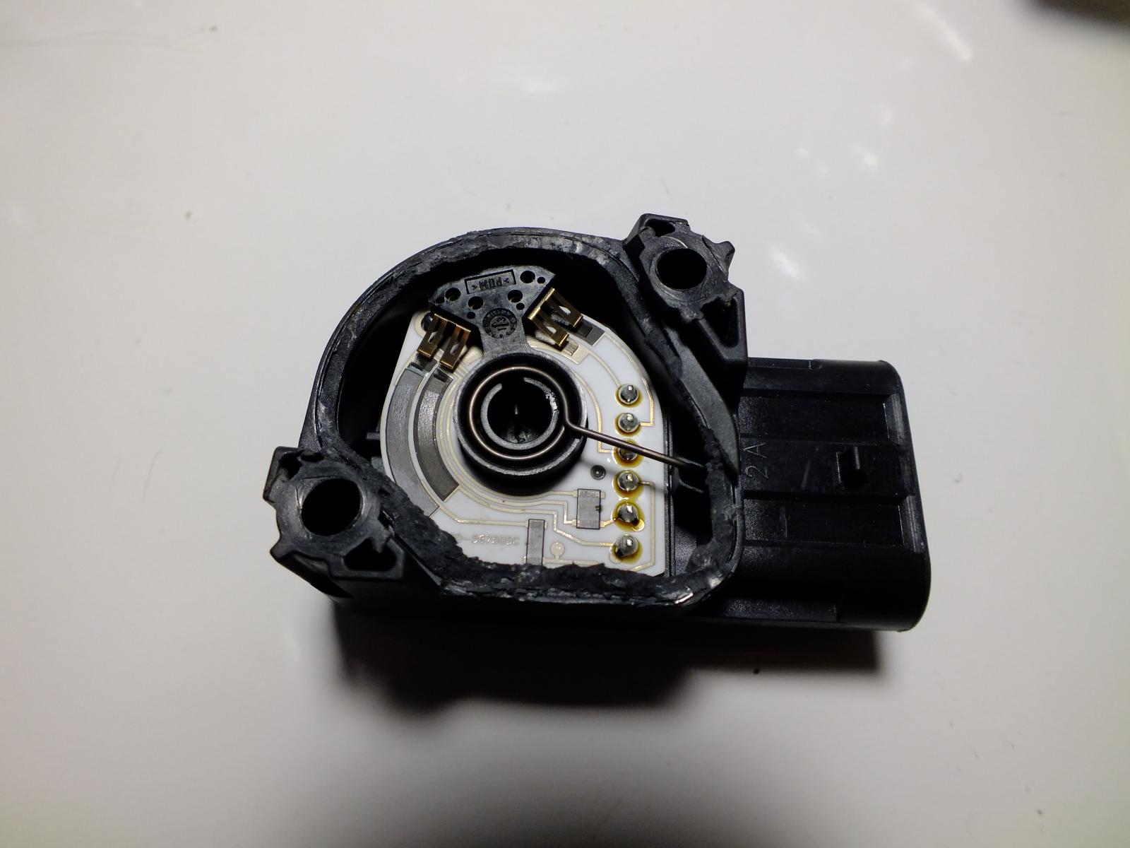
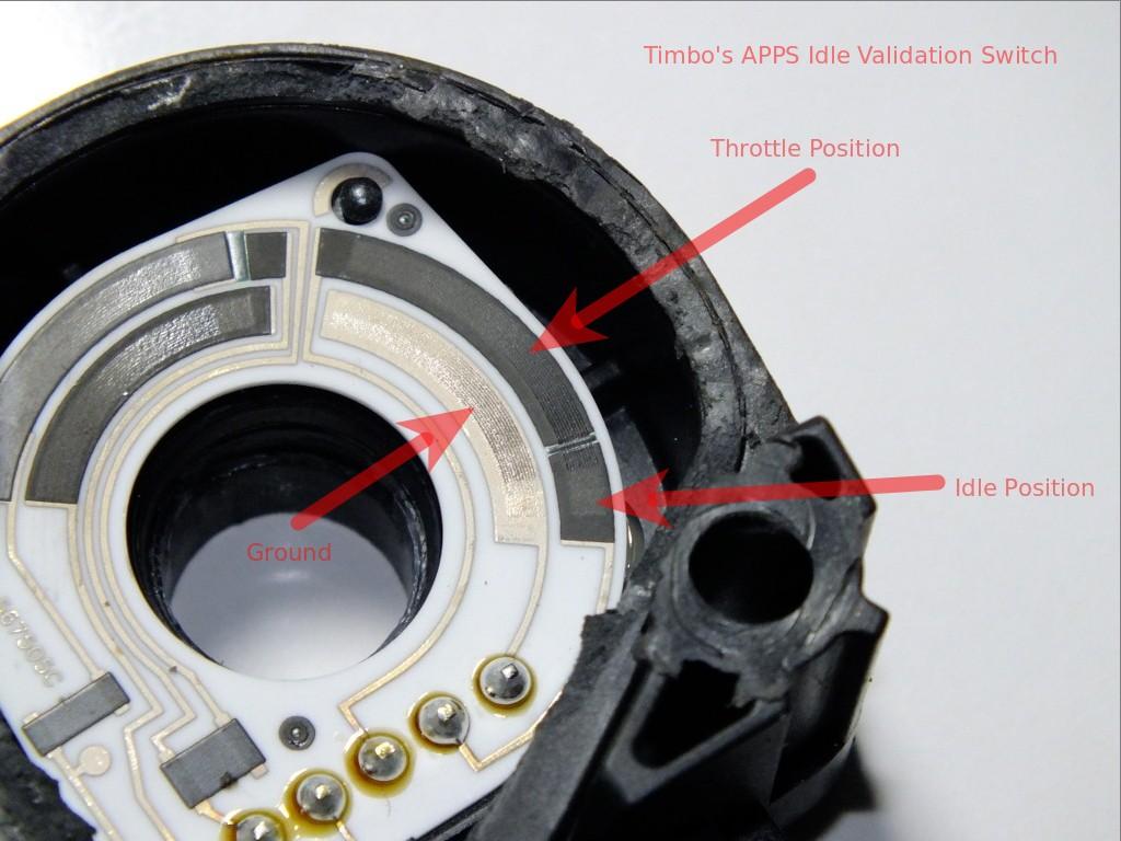
I know that Auto Computer Specialist actually rebuild wiring looms. https://mopar1973man.com/forums/forum/210-auto-computer-specialist/ The voltage of the APPS seems low at .112 volts. I would suggest getting a Timbo APPS and ditch the old voltage APPS of the OEM and Wells (Magnetics). Timbo APPS is a true mechanical APPS. Bad idea.. Again, that is not how that system works. That voltage is determined by the sensor; each manufacturer is differen,t and the value never matches!
-
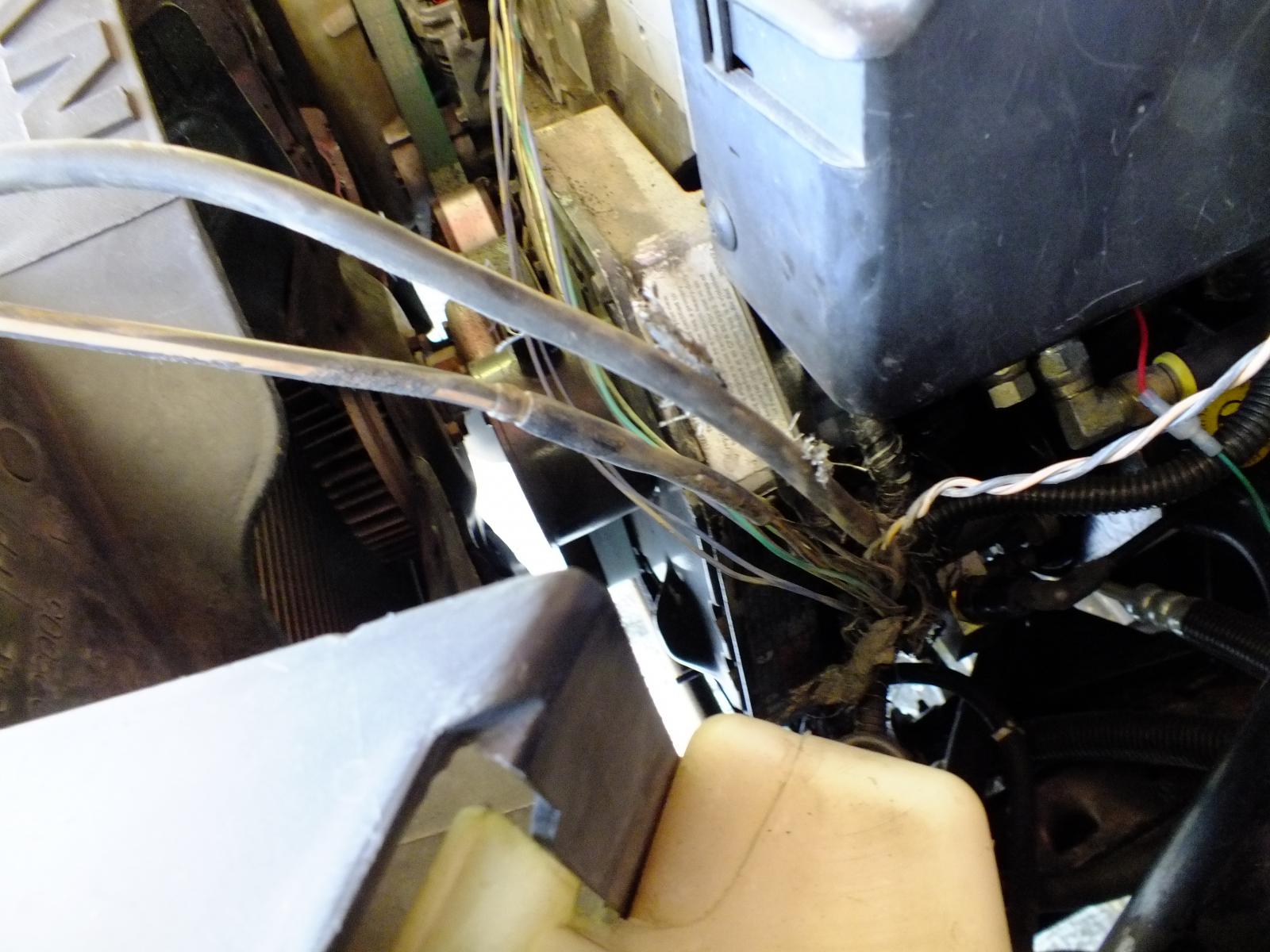
Basically, in a nutshell, the alternator charge line is hooked to the passenger side battery. The engine grounds for the ECM and VP44 are separated and relocated to the driver's side battery, so the ground cannot be cross-polluted by the fact that the positive charge line is run next to the master ground for the engine. AC noise jump in that 4-foot run of wiring. So the mod was to separate the positive charge line away from the master grounds for the VP44 and ECM. Ground on the left (black/tan) and alternator charge on the right (black) then the crush crimp of ground wires under the black tubing on the black/tan wire.
-
If ACS said the ECM is good then check wiring for faults shorts etc.
-
-
-
-
-
-
ECM might have a bad solder joint that is breaking connection during warm up. Test you electrical (wiring first to be sure).
-
First problem, there is no 24 valve 6BT engine. They were all 12-valved engines. Then the 6-speed NV5600 was released in 2000 with the high output 24V 5.9L ISB engine trucks. Now as for getting rid of the ECM it won't happen because you need the ECM for gauges like coolant and oil pressure. The p-pump was a bad choice for swapping to being its a static timed pump and had zero advancement technology where the VP44 has a full range of 30 degree BTDC worth of advancement. Cluster requires the ECM to report the oil pressure, volts come from the PCM, fuel gauge from the PCM and the coolant temperature.
-
Good question. Ubuntu seems to be the best all-around software I found that works with the equipment I've got here. I like the idea that when I get to a company like TP-Link for network devices, they have Ubuntu Ready software now! Most Ubuntu software has been fairly easy to install. Then, as for usage, I enjoy both the Ubuntu Desktop series on the workstations, but then we have a Ubuntu Server here at the house, which soon will allow me to play with a sandbox version of the website for building code. Now, like the website, which is on a Redhat family of AlmaLinux. You're right, there is a huge family tree here. https://en.wikipedia.org/wiki/List_of_Linux_distributions#/media/File:Linux_Distribution_Timeline.svg I've played with several versions of Linux, but I just seem to come back to Ubuntu for stability-wise, ease of installing software, and most software is ready for Ubuntu. Like when I built the new workstations, I was kind of wondering what hardware issues I would run into. One was that Ubuntu didn't set up the nVidia drivers correctly, and the video would crash before the post finished. After now changing the video driver to the nVidia proprietary nVidia drivers that are tested, BOOM! Everything worked correctly. I'm versed in both Red Hat and Debian Families of Linux and can go either way.