Rogan
Retired Staff
-
Joined
-
Last visited
Everything posted by Rogan
-
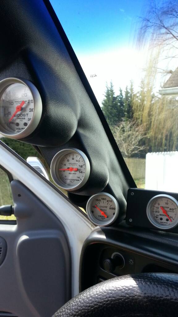
ISX, I replaced the new ofv with the old one, and stretched the spring a tad as well as added a little piece of a pen spring.. boost gauge in lower right is my temporary fuel pressure. With the "new" ofv before, it idles arould 16ish and I never saw higher than 20psi. This OEM modded one's pressure is pictured below.[ATTACH]5226[/ATTACH]Sent from my SPH-L710 using Tapatalk 2

-
I've got one such device.. 3M Stripe Off wheel.. http://www.google.com/url?sa=t&rct=j&q=&esrc=s&source=web&cd=1&sqi=2&ved=0CFEQFjAA&url=http%3A%2F%2Fwww.amazon.com%2F3M-7498-STRIPE-WHEEL-W-ARBOR%2Fdp%2FB00063VT0G&ei=EytNUbWuHIbY9QSx44HoBw&usg=AFQjCNGTaABEcLraKnfC0NI9_E9CKG__SA&bvm=bv.44158598,d.eWU&cad=rja
-
I like the debate-side of things. I want you to, first and foremost, understand that I do not think horsepower doesn't matter. It all has relevance. However, in my past tuning history (having built many high HP/TQ turbo cars) during the "tuning" process of the ECM on the dyno and on the street, I focused on 3 major things (in order) Air/Fuel ratio, knock, and torque curve. The Horsepower always followed, but chasing HP numbers was a waste of time. Sure, I could tune my 575whp Subaru WRX to make 600+hp, but the torque curve looked like a roller coaster's initial hill climb; worthless. I'll see if I can find an old dyno plot for this car at 575 peak hp; the torque plot was insanely flat for about 2/3 of the pull. The car stayed in the 400s of lbft Tq from around 3500ish, all the way to about 5800rpm. As well, the AFRs sat near rock-solid of 11.5:1 (used 50/50 water/meth injection to compensate for the "leaner" AFRs.) It stayed above 300lbft to about 6500, then petered out above that to the 7650rpm redline I set for the engine. ** Why did it peter out? My GT35R turbo had too small A/R turbine housing (.63 AR) and ran out of cojones. **I built it to spin safely to 9000, and did hit 8500 a couple times. If you've never been in a car spinning 8500-9000rpm, it's a bit un-nerving
-
A 'play' on what Mike said, is what we used to say in drag racing circles (yes, I used to drag race turbo cars).."Torque gets you E.T. Horsepower gets you 'mile-an-hour'."
-
http://forum.mopar1973man.com/threads/7526-Article-Turbochargers-A-R-Trim-and-Flanges
-
I don't take it that way.However, this article was more for those "who don't understand" the relation; apparently, you aren't in that group :)You and I would eventually funnel down to the same conclusion/result, we're just looking at the same thing from two different angles.As for the gear ratios, I know they don't change Tq or HP. My point was towards your reference of RPM = speed. On a 1:1 ratio, your example would be spot on, by a long shot. But with different ratios, that changes dramatically.
-
What is an A/R ratio and how is it calculated?: The A/R in a relationship that is obtained when dividing the interior area of the turbine where the inner walls are found, through the turbine housing radio from the center to the tongue as the illustration indicates. A/R values are expressed as .35, .47, .68, .84, 1.00, 1.15, etc. A small A/R indicates a small interior volume in the small turbine and a large A/R indicates a greater volume. At a minimum A/R the motor's response is produced at small revolutions per minute but at high revolutions we will not achieve an adequate caudal. We should always find a compromise between achieving the lowest response possible and have enough caudal at high revolutions. The picture below is for reference: As stated, the turbine housing A/R is the cross sectional area of the turbine housing divided by the distance from the center of that cross section to the center of the wheel. This makes sense if you look at the graphic. If you take for example, the area in A1 and divide it by R1, you will have found the A/R for this turbine housing. Each cross section and radius have the same proportions so the A/R will be found by using any cross section/radius. What is the Trim of a turbo and how is it calculated? Each turbine wheel y compressor wheel model generally have the same turbine diameter (highest diameter), but different steps (lowest diameter). Each type of step (trim), has different blowing characteristics. [*]TRIM values are expressed as 45, 50, 55, etc... and can only go from 0 to 100. A value of 100 means Dp = Dg [*]A large TRIM indicates a large turbine diameter. [*]A TRIM of 55, gives 10% more caudal than a TRIM of 50. [*]TRIM is used in the same way for turbine wheels as for compressor wheels. [*]TRIM is calculated through the following formula. TRIM = ( Dp / Dg )² x 100 Si Dg = 50 mm y Dp = 35 mm TRIM = ( 35/50 )² x 100 = 49 What are the different flanges and what are the sizes? [*]All most all of your turbo head units come with the flanges described below. The T3 housing is the smallest and flows the least, with the T6/Thumper flange being the biggest and flowing the most. The flange plays a role in spool up, backpressure...etc. The rule of thumb here is use the largest flange you can possibly fit. Of course this will be limited by what headers you use, since most are pre-fabbed and come with a flange already, and under hood space will also be a limitation. [*]Basic T3 [*]Basic T4 [*]Basic T6
-
You're right, it is something to keep in mind.. HOWEVER.. 8000rpm and 700lbft TQ moving faster than 2500rpm @ 700lbft Tq is a a variable. 8000rpm through 5.38:1 R/P on a 28" tire, and 2500rpm with a 2.79:1 R/P on a 28" tire are two different animals.I'm not against a horsepower #, but without Torque, HP cannot be calculated, period. That does not hold true for HP calculation's reliance on torque.Torque = Force x Distance
-
Thanks, JR. I'm actually still troubleshooting some of his requests, and this thread is part of that
-
no one?
-
For the last century, horsepower has been used to describe the power output of the internal combustion engine. The horsepower unit was created by James Watt in the 18th century. Its origin is based from how much power a horse could lift in foot pounds, 33,000 ft-lbs to be exact in one minute. The unit is derived from torque, which is the true measurement of the engine physical power production. What is strange about the units of horsepower is that it has no physical meaning. Its an arbitrary unit that has no real significance in describing the characteristic of the engine. For those that are curious to calculate horsepower: horsepower = (rpm/5252) * torque From this equation you can see that horsepower is nothing more than a contrived unit that is based purely from torque and rpm. You’ll notice the number 5252 in the equation, this represents the point at which every dyno graph must intersect horsepower and torque. Its a mathematical relationship, both strange and interesting since horsepower is a function of torque and rpm. There has been much confusion and rumors across the internet about gaining more horsepower. In essence, gaining more horsepower is gaining torque. If you are after “peak” horsepower, you are interesting in carrying the torque curve as high in the rpm range without falling as possible. You can see from the equation that as the rpm’s increase, and the torque remains the same you get a higher horsepower number. What physically is happening is that the engine is able to produce enough torque to overcome frictional forces through the air, tires, etc. As you are able to keep the torque from falling off on the top end, you are able to maintain a steady torque curve that will “pull” the car through the mph you are trying to reach. So people who are after “peak” horsepower really want to extend their torque curves as far towards redline as possible, without letting the torque fall off. Check out some dyno graphs and see what I mean. Horsepower doesn't describe the true nature of how the engine performs, its the torque curve. From a tuners perspective, I don't tune off of the horsepower curves. The physical relevance towards the engine performance is arbitrary, since the torque is truly what is effected by the fuel, timing, breathing, etc of the engine. The horsepower is merely a concocted unit of measure, showing no true characteristics of the engine power output. A good tuner will only make changes from the torque curves, see what increase/decrease the curves show from the changes. So next time you are thinking horsepower, think “what would I want my torque curve to be”?
-
Everyone seems to grasp that a larger exhaust on a turbocharger vehicle will gain faster spool up, increased power and thus faster acceleration. Here is the theory behind the phenomenon: The turbine housing is merely a volume for which exhaust gas (energy) is transmitted from the engine, to the turbine blade, then dispelled into the atmosphere. In order to better understand how this works we need to take a look at pressure. Turbines in general work off of a pressure differential. A pressure differential in layman's terms is the ratio of pressure before the turbine blade, and after the turbine blade. The greater the pre-turbine pressure compared to the post-turbine pressure, the greater the amount of work can be transmitted through the turbine/compressor shaft. This is where some engineering comes into play. Work is defined as the integration of force and displacement, keeping force constant. Again in layman's terms this merely means work is the force exerted on an object while taking into account the change in displacement, or position of the object. In relation to turbines, the greater the pressure differential, the greater the amount of work is created. The greater the amount of work created, the greater the amount of energy transmitted through the turbine, into the compressor through the connecting shaft. To break this down into another small explanation, compressors work off of rpm. The amount of air the compressor is able to “flow”, or merely put the lbs/minute the compressor can flow is dictated by the amount compressor blades, angles of the blades, etc. What the compressor uses to “compress” the air through the inlet is based off of how fast the compressor wheel is spun. The rpm at which the compressor blade has to be spun to “compress” the air varies from turbo to turbo from the different compressor blade characteristics. Another critical aspect of the compressor is the physical size and weight of the blade. The larger the blade, more amount of energy must be transmitted to allow the shaft to spin to the rpm at which the compressor can compress the air. In engineering terms rotating mass is called inertia, so smaller turbos have smaller inertia demands, larger compressors have larger inertia demands. To bring the focus back on the turbine side of things, the increased inertia demands more energy to be supplied from the turbine. The greater the pressure differential discussed above, the greater the amount of work that be be supplied to overcome the inertia effects of the compressor. Now looking at the exhaust, or post turbine the larger the exhaust, the larger the pressure differential can become. The increase in area of the exhaust, gives the exhaust gas much more room to expand. Hot gas has only one goal, to expand as quickly as possible. The goal pre-turbine is to focus the energy into the turbine to carry as much energy as possible. As the exhaust expands the energy dissipates, so the goal post turbine (i.e exhaust) is to have the largest area possible for the gas to expand. Looking at the immediate exit of the turbine housing, the downpipe, the exhaust gas is traveling at a very high rate of speed. The exhaust gas is expanding rapidly, and is in a very turbulence state from being flung from the turbine. At this point having a 3″ down-pipe becomes critical since the exhaust gas is both in a turbulent state, and is expanding. In turbulence, the expansion of an area the turbulence is forced to become more laminar (although this doesn't happen very quickly). Also the increased area allows the gas to expand rapidly, allowing the energy in the exhaust gas to dissipate quickly and letting the pressure created by the exit from the turbine housing to drop. Essentially you are creating a greater pressure drop. Looking at the turbine housing the sizing becomes a critical part in how the pressure differential is created. Take for instance the .48 A/R housing. Changing turbine A/R has many effects. By going to a larger turbine A/R, the turbo comes up on boost at a higher engine speed, the flow capacity of the turbine is increased and less flow is wastegated, there is less engine back pressure, and engine volumetric efficiency is increased resulting in more overall power. The .48 A/R is able to create the pressure differential at a much lower engine rpm, giving the compressor ability to make its maximum rpm speed sooner. As the engine rpm climbs, the pressure differential is lowered due to the physical volume of the housing size becoming a restriction on the post turbine side. As the housing size is increased, it take greater engine rpm speed (greater exhaust energy) to spool up the turbine, but the pressure differential is less effected by the physical volume of the housing. If you are after maximum midrange gains smaller housings are essentially, if top end gains are essential larger housing are essential. Selecting the power band of the engine is essentially dictated through the housing size, and the turbine physical characteristics.
-
Turbochargers while simple in design, can get very complex in theory. From deciding what compressor trim is desired, to what turbine housing to be used is confusing to most who enter the field of forced induction. This article will hopefully take away all the confusion in turbocharger selection. Terminology Before I can begin writing an article explaining turbochargers, terminology must be learned. Here is a list of the more commonly used turbocharger terms: Compressor - Essentially a fan that spins and compresses air within an enclosed area (compressor housing). In order to allow the air to compress and build pressure within the housing, the fan must be spun at certain rpm levels. Compressor Housing - Housing that encloses the compressor. Pictured is a compressor housing. Compressor Map – A map that allows the ability to plot compressor pressure ratio vs. engine airflow. An “island” shape is created on the plot showing where the compressor is efficient. Compressor Efficiency – Compressors efficiency is the ability to produce lowest possible temperature from the compressor air. When air is compressed heat is generated, at certain range of speeds of the compressor rotation the heat can be keep to a minimum. This is what is known as “being in the efficiency range of a compressor” Higher efficiency, lower outlet temperatures. Highest possible efficiency of compressors are 78~82%. Lower outlet temperature=lower intake air temperature. Lower intake air temperature=more dense mixture of air=more oxygen available in the combustion to burn. The greater amount of oxygen present with fuel provides more energy. More energy=more heat=more torque=more power. Compressor Trim – The trim of the compressor refers to the squared ratio of the smaller diameter divided by the larger diameter multiplied by 100 of the compressor wheel. The smaller diameter of the wheel is known as the inducer, and the larger diameter of the wheel is known as the exducer. Compressor Families – Beyond compressor trim levels there is compressor family of wheels. In the Garret turbo line of older technology compressors there is T22, T25, T3, T350, T04b, T04e, T04s and T04r families. In each family there is trim levels to the family. Although there is a 60 trim in both the t3 and to4e family wheels, the main difference is the inducer diameter of the wheels. The trim is only a ratio of the exducer/inducer, so while the inducer size of the compressor wheels are vastly different, the ratio between the exducer/inducer remains constant since it’s the comparison between the exducer to inducer size. Turbine – A fan that uses exhaust energy to rotate. The rotation of the turbine is transmitted through a shaft that is connected to the compressor. Faster the turbine spins, faster the compressor spins. Compressor uses the rpm translation through the turbine/compressor-connecting shaft to compress air at the rpm level that dictates compressor flow. Turbine Housing – Housing that encloses the turbine wheel. Turbine housing size affects the ability of the turbine to transmit rpm to the compressor wheel. Smaller turbine housing, quicker spool up due to quicker translation of rpm’s to compressor. Trade-off is increased low-end response for less high-end response from turbocharger. Picture below is a turbine housing. Turbine Trim – The trim of the turbine refers to the squared ratio of the smaller diameter divided by the larger diameter multiplied by 100 of the compressor wheel. The smaller diameter of the wheel is known as the inducer, and the larger diameter of the wheel is known as the exducer. Turbine Families – As with compressor families, there is turbine families. The most common evidence of the turbine families is the t31, t350 and t04 wheel used in the t3, t3/t4 turbos sold on the market. Precision offers the t31, aka stage 3 blade in their smaller line of sport compact series turbochargers. The t31 comes in two different trim levels the 69 and 76 trim. The t350, aka stage 5 blade comes in two different trim levels as well, 69 and 76 trim. The t31 will spool faster than the t350 due to the physical size differences (t31 being smaller). The smaller the trim level the quicker spool, but less top end. Essentially you are changing the turbine pressure ratio when you are selecting the family and trim level of the turbine wheel you are using. The larger family and trim level you choose the more power the turbocharger will produce at the expense of lag. As with the compressor trim levels both the t31 and t350 have the 69 and 76 trim levels, which are not the same. The turbine trim is the ratio of the exducer compared to the inducer size of the turbine wheel, since its only a ratio the size of the inducer/exducers are completely different. Turbine Map – A map that allows the ability to plot turbine expansion ratio vs. engine airflow. An “island” shape is created on the plot showing where the turbine is efficient. A/R – Ratio of the area of the compressor/turbine housing to the radius of the compressor/turbine wheel. In order to find out the A/R of the compressor or turbine housing select a point where the compressor/turbine housing begins and measure the cross-sectional area at that point. Cross sectional area is A=P*(Radius)2. Next step is to measure the distance between the center of the area and the center of the compressor/turbine wheel, this is the radius measurement. If you choose a different point on the compressor/turbine housing and remeasure the area and radius, you’ll find that it stays constant. This is due to the housing getting constantly smaller in diameter as it gets closer and closer to the compressor/turbine wheel. When you upgrade from a .48 to a .63, or .63 to a .82 A/R you are essentially increasing the area of the housing. Increasing the area increases the amount airflow to the turbine wheel. The smaller area of the smaller turbine housing builds pressure quickly and transmits this pressure to the turbine. The pressure gives the turbine enough rpm’s to allow the compressor to compress air at lower engine speeds (less engine speed, less airflow from engine). The trade off is that pressure builds up quickly in the housing to obtain quick spool up, but the pressure quickly becomes to great and backpressure builds up. The backpressure is the restriction that limits shaft speed of the compressor, and as the rpm increase (engine airflow increases) the torque curve begins to drop off due to the volumetric efficiency of the engine decreasing. Think of the turbine housing sizing as increasing/decreasing inlet pressure to the housing in order to gain low end, midrange or top-end response from the turbocharger. The smaller turbine housing wont carry the torque curve to a high rpm, limiting the amount of peak whp. Excellent low-end and midrange gains are felt through smaller housings. Compressor/Turbine Mismatch – When “matching” a compressor and a turbine you are seeking to balance the turbine characteristics to the compressor characteristics. When you increase the size of the turbine wheel you are decreasing the pressure ratio of the turbine, essentially decreasing the shaft speed connecting the compressor/turbine. When pairing a larger turbine wheel to a small compressor wheel, the smaller the compressor wheel the higher the rpm the wheel has to be spun at to compress the air. This becomes a problem in that the smaller compressor cannot generate adequate shaft speed to compress air. The same can hold true when pairing a huge compressor to a small turbine wheel. The larger compressor needs less shaft speed to compressor airflow, but the smaller turbine wheel will spin at a much higher rpm level that is what is necessary. The result is crossing over the choke or surge line on the compressor map (this will be explained in part 2 of this article). Note the two different compressor maps, one of a 60 trim t3 compressor wheel, the other a t64 compressor wheel. Part 2 will explain compressor and turbine maps, and all the terminology that goes along with topics.
-
The author of this article is a turbo engineer for Garrett. I'm submitting it because it is an informative read and therefore is beneficial to the community. Enjoy. Compressor Efficiency and More by Khiem Dinh Compressor efficiency is a term thrown around whenever people mention forced induction, but what does it really mean? How does it affect an engine's performance? And what role does air temperature play in all of this? The cool thing about thermodynamics is that we can explain effects with equations. Using basic compressor equations, we'll put some numbers to the affects of air temperature and compressor efficiency on compressor power requirements and air temperature increase. Some fundamental compressor equations are below. I like working in SI units because doing calculations with English units sucks! So, mass flow rate is in kg/sec, the average constant specific heat value for air I used is 1.007 kJ/kg*k, and k for air is 1.4. The specific heat of air actually varies with temperature, but the change is basically nothing within the range of temperatures we're using, so I'm assuming a constant value. After calculating all the values in SI units, it is a simple conversion to English units. The table and chart I generated assumes: air inlet temperature of 298K/24.85C/76.7F, and 100% compressor efficiency (isentropic compression). Looking at the chart and table above, it becomes very obvious that increases in mass flow rate and pressure ratio require more power. Also, the graph shows lines of constant power. For a given compressor power, you can get a lot of flow and little pressure ratio, a lot of pressure ratio and little flow, or somewhere in the middle. To get a feel for what the numbers mean in the real world, we'll use 2.0L 4-cylinder engine as an example. Automotive engines of this displacement and cylinder count will make roughly 500hp with a mass flow rate of 50lbs/min and a pressure ratio of 2.75, or about 25psi of boost. Looking at the table, a 100% efficient compressor would require 51.1hp! Looking at the compressor map for a GT3076, it shows a compressor efficiency of ~72% at this point. So the actual power requirement becomes 71hp. A GTX3582 has a compressor efficiency of 77% resulting in a power requirement of 66.4hp. That extra hp required over a 100% efficient compressor ends up as extra heat in the air. More efficient is better! The other variable in the equation that's very important, but many people seem to neglect in the practice of building turbo cars, is the temperature of the air going into the compressor. Many people have the misconception that performance is unaffected because the intercooler will cool the air enough regardless of the air temp going into the turbo. What they are neglecting is the fact that compressor performance improves with cooler air. Said another way, it gets worse with taking in hotter air. Using values of 50lbs/min and a PR of 2.75, the table below shows compressor power required, change in temperature of the air (Delta T), and the exit temperature of the air based on the inlet temperature of the air. Hotter air in equals mo' hotta air out! Takes more power too. Translation? Laggy turbo. Notice that the hotter the air going into the compressor, the more power is required to compress it. Also, the increase in the air temperature is greater. Of course, this results in the final temperature being even hotter. I think comparing air inlet temps of 77F and 122F is reasonable; 77F being ambient air temp and 122F being the temp if you ingest air from the engine bay. So by sucking up the hotter engine bay air instead of cooler air from the front of the car, the compressor power required increases by 4.3hp, or about 8%. The difference in the temperature coming out of the compressor is a toasty 60.1F making the intercooler work that much harder. Of course, there's no such thing as a perfect compressor, so let's see what happens with a 60% efficient compressor; this is often where the tuner industry operates as they try to squeeze as much power as possible out of turbos. Looking again at 77F and 122F inlet temps, the power and temperature differences are now 7.1hp and 70.2F! Crappy compressor efficiency means supa dupa hotta air! You could boil an egg on it. Mo' laggy too. So now we know how crappy compressor efficiency and sucking in hot air increase the power required of a compressor to move and squeeze air. But where does that power come from? A supercharger gets it off the crankshaft of the engine and a turbocharger uses a turbine wheel in the exhaust. If you go by old school nomenclature, what we call a turbocharger was referred to as a turbo supercharger. So basically a special type of supercharger with a turbine wheel to get work out of the exhaust. Anyways, we like turbos because they use otherwise wasted energy. Going back to the very first chart, a perfect compressor doing 100lbs/min at a pressure ratio of 4 would need almost 150hp. Given the option of taking that from the engine crankshaft or the exhaust energy, we'll take the exhaust energy. That's the reason why pretty much every diesel engine and the majority of gasoline engines use turbos instead of superchargers. So does the turbo engine make 150hp more than the supercharged engine? The answer is no because the turbine wheel and turbine housing create back pressure in the engine reducing its volumetric efficiency. But a turbo engine will still make significantly more power than a supercharged engine given the turbo is properly sized. Sizing of the turbine wheel is important so as to get the maximum efficiency from it. Our worst case scenario of the 2.0L engine, 60% efficient compressor, 50lbs/min mass flow rate, 2.75 PR, and 122F air inlet temperature requires 92.4 hp of shaft power from the turbine to drive the compressor wheel. A 100% efficient turbine wheel would need to get 92.4 hp worth of energy out of the exhaust. However, like compressor wheels, there’s no such thing as a 100% efficient turbine wheel. Throw in some moderate turbine efficiency and you end up needing a lot of exhaust power to spin a compressor. Plugging in a value of 60% for turbine efficiency, we can see how much energy needs to be pulled from the exhaust based on the temperature of the air going into the turbo. The difference in power required going from 77F and 122F is a lag inducing 11.9 hp, or about 8%. So what have we learned? Maximizing compressor and turbine efficiencies reduces the exhaust energy required to get a turbo going. Sucking in colder air instead of hot air also makes compressors happy. The final conclusion to all of this is that math is cool, stay in school!
-
I partly disagree with your mechanic, as far as OEM is the only way to go.Theoretically, if the OEM parts were so much 'better', then there shouldn't be any new car/truck returning from the dealer for service/repairs.. :shrug:As for dripley's comment, that is true. In my case, I had already replaced bearings, ball joints, TREs, track bar, etc., but still had a significant amount of steering input required to keep the truck straight.. Like 60* of steering input to stay straight in my lane on the highway. That's a lot of correction. The Steering Brace, for $100 or whatever I paid for it, reduced that by half!My steering gear box had a lot of lateral play in the output shaft. The SB put that in check..
-
I don't think mine has ever came loose. I don't think that 'falling off' would be an issue.. Oh, and for whoever asked, here's a pic I found while surfing for something completely different.. http://forum.mopar1973man.com/attachment.php?attachmentid=5223&d=1363919908

-
Sorry, I didn't see the first picture, only the 2nd one. I thought the torx was the odd one.. DEFINITELY replace all of those torx bolts. IMO, that's one of the most worthless fasteners ever.. - - - Updated - - - Sorry, I didn't see the first picture, only the 2nd one. I thought the torx was the odd one.. DEFINITELY replace all of those torx bolts. IMO, that's one of the most worthless fasteners ever..
-
Given the weight of the Cummins, the age of these suspensions, I wouldn't call adding a steering brace a waste of money. My 2001 steered 100 times better than without it.. It took out about 90% of my steering wander.
-
...and rain water
-
I see no reason to cause issues with just replacing the one odd-ball bolt.
-
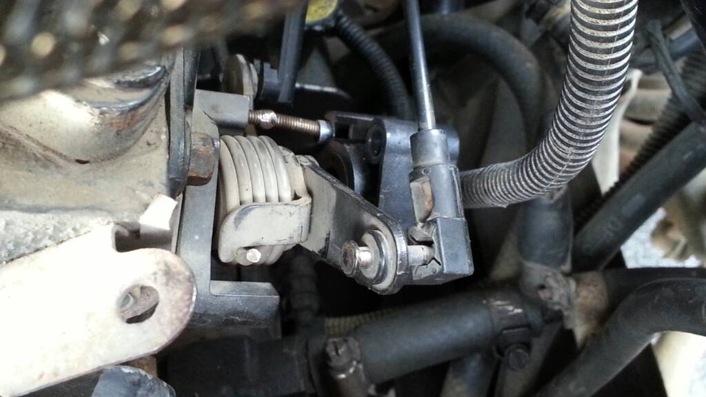
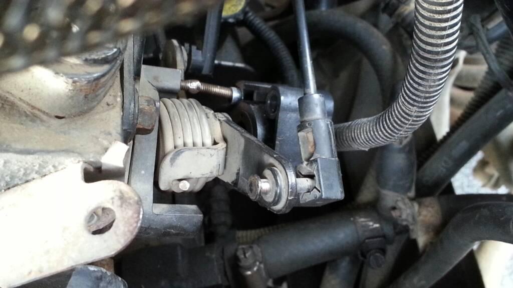
Here is mine. As you can see, there's the base portion of the bracket to the left of the springs. The right side (in picture) is totally missing. The SINGLE screw holding the TPS is two screws welded together LOL.. My buddy's '95 is completely different, as the bracket to mount the TPS on his looks to be a single piece, rather than a 2 piece on mine.. Bear in mind that my truck was originally a 5 speed, so no TPS was there to begin with. http://forum.mopar1973man.com/attachment.php?attachmentid=5219&d=1363873374
-
You guys with a 12V auto.. Can I get someone to take a picture of the throttle linkage/tps section of your truck for me? Basically, I'm trying to determine the correct layout to fix my truck.The PO hodge-podged this entire truck. The TPS setup on my truck is so redneck, that I feel embarrassed to call myself a redneck.I'll post a pic shortly of what my current catastrophically engineered TPS mount looks like..I've got a buddy that has a '95 Auto converted to 5 speed. He no longer needs his TPS and bracketry, and said I could have it. Well, his looks completely different than my '97.Thanks.
-
that'll buff out. Seriously though, sorry about your luck. I know just how it is though. Same kinda @#$% I am going through with my 'new' truck.. Sent from my SPH-L710 using Tapatalk 2
-
ISX, I found the rubber line and pinched it down. Pressure shot up to like 35psi fp! So I'm thinking the new OFV is no Bueno. Sent from my SPH-L710 using Tapatalk 2
-
On the way home from work last night, the truck put me to the side of the road with 'no throttle response'..Investigation led me to the rod from the linkage to the pump had 'unthreaded itself'.. I fiddled in the dark to get it back together. I remember seeing somewhere the proper length of this rod, but cannot find it now. Anyone know, off-hand? Thanks.