

W-T
Yearly Subscription
-
Joined
-
Last visited
-
Very sorry to hear this, be well. W-T
-
@LD-Ordie I have a Smarty and I also return to stock settings every two years for the Smog check. Once the Smarty is hooked up I always clear the "over boost" code because the Smarty fuels passed the 20 psi limit of Factory programing. I also return to "stock tire size" because I'm rolling on 37" tires. I don't have any other codes and once you return to Stock Factory spec's your Smarty leaves no foot print of being involved with programing. That feature was specifically engineered by Marco in Italy over 20 years ago. It works flawlessly and I have never experienced an error in 20 plus years. NOW...as for you stacking an Edge product with the Smarty, I do not know why you would do such a thing, are you also removing the Edge device and allowing the Smarty to clear what ever mess that leaves behind? If so, do you see a clean report from your Smarty once you clear everything? The Smarty will clear codes completely but, if you have an error and a code returns after clearing it with your Smarty...you have homework to do. I'm not scolding you but, stacking programmers is so hayseed lame. Get a Quadzilla and do to it right, you won't regret that. (I love spending other peoples money) If you do not have any errors, your Smarty will clear standing codes and you can roll into your Smog inspection station with NO fear. Respectfully, W-T
-
Yeah...me too, I was under the passenger side the other day and I found a spot of dirt so I freaked out, ran to get some Q-tips and a tooth brush to fix it! Boy, am I glad I found that, I would have been mortified if someone had seen that...I was just lucky to have found it before anything had gone wrong!
-
These lift pumps we are referring to, are all mechanical Cavity Gear pumps. Most all of us, are familiar with this design and the history in the automotive industry exceeds 50 years or more. Yes, as John @Tractorman has pointed out these are positive displacement pumps and by design they are modest in their ability to manipulate liquid material in a closed environment. This environment has restrictive characteristics at both inlet (feed point) and outlet (discharge) aspects, that in design, these pumps can over come these resistive road blocks and deliver diesel fuel reasonably well. However ; the term "reasonably well" has limits due to the modest nature of these Cavity Gear pumps. These little pumps are great for the purpose they were designed for but....do not expect them to operate in a poorly designed or maintained transfer system. The ability to draw liquid diesel fuel with these wimpy little pumps requires a clean low restriction feed method,...meaning NO Oatmeal in the screen basket within the fuel tank. I know...everyone knows this...but, if you can't see your wetted-feed point within the tank, I would suggest inspecting that aspect. Any minor air leak that may not be evident in a cold environment may very well become apparent once the environment changes thermally. Usually fittings with a mated surface for point to point surface contact will prevent liquid seepage but, this same fitting could suck-air and hinder pump operation once the thermal threshold has been met and exacerbates the expansion/contraction coefficient of the metal components in service. Air is easier to suck through a straw compared to a milkshake so, the effort to find an elusive air-leak that is so incredibly tiny is a challenge. Avoid the "just tighten the crap out of the fitting" method. Always apply light lubrication to the "mated fitting's" surfaces, prior to mating them and avoid galling the jeweled surfaces. @Basranabread I'm only trying for a simple solution, and I appreciate your diligence along with excellent commentary and it is your information that leads me back to the primary observations. It causes me to suspect an air leak. The condition within your fuel tank that can't be seen for verification would be a resistive element. Going back to the modest design of these pumps and how small errors will lead to faulty performance, it is just the nature of this particular design. The system design is providing liquid pressure maximums of 15 to 20 PSI and these characteristics place this style of pump into the "Peanut Whistle" category where very small leakage errors cripple the performance drastically. Your observation of "noisy pump" and once re-primed....goes quiet....tells me it's sucking air. Oh...yeah, what O-ring?....you're scaring me when you placed that into the "what if " equation. Respectfully, W-T
-
@jlwelding what @LorenShas shared here is correct...to be fully accurate, I too, did the same with the Carter lift-pump bracket. The small block Chevy block off plate I purchased from NAPA was my choice however; once I removed the "dog legged" bracket of the old lift pump, it was easy to see only a slight cut-off trim job was required to create a clean fitment. I returned my Chevy block-off plate and utilized the return to purchase a can of spray paint. Gosh...I guess my old memory is beginning to fail...Loren, thanks for correcting this aspect, why spend the funds when the block-off element is available to accomplish the task.
-
It's an excellent modification to clean up that area of the engine compartment. You'll find the chrome-plated mechanical fuel pump "block-off-plate" available at nearly every auto part store or on-line source. I have done this myself and it's very easy to perform, plus it looks better. I think I spent $6 at NAPA (years back) and it includes the gasket. Yep...my bad, I should have noted @dieselautopower first, they have all the cool stuff !
-
I carefully reviewed my post for spilling errors before I posted I kneed to be a bit more kareful.
-
@Andyba20 The ambient temperature is measured by the IAT to allow the ECM to adjust perimeters for proper engine running conditions. The battery temperature sensor on the drivers side is the element that determines charge rate. The thermal change or stress to the battery case is provided to the PCM via this particular sensor to limit the amount of current generated by the alternator. The "two" batteries being less than 4 months old...disconnect the adjoining cables and with your DVM verify both batteries are equal in static DC potential. Each battery should reflect nearly identical voltage levels. One may show 12.6 volts the other may show 12.5 volts and this is acceptable. If you have one storage cell at 12.2 (just approximate) and the other is 11.5 volts (as an example) this indicates a damaged cell within the battery that is showing 11.5 volts. This damaged cell will continually draw current from the healthy battery and this discharge will pull the 'head charge" off the healthy storage cell in this parallel configuration. NOTE: All storage cells are static at 12.6 volts. Anything less than 12.6 is considered discharged and requires replenishment via the charging system. Ground is so very important especially in "high current" generation systems. Please examine your alternator's mechanical mounting system. The case of the alternator is the main ground reference for your diode stack within the alternator. The PCM controls the charge as Mike @Mopar1973Man has pointed out utilizing the "green wire" from the PCM as a variable "ground reference" to vary the amount of current being generated. If the integrity of the ground between the alternator's case structure is compromised the PCM can not track charge rate correctly. Under high current demand (operating a wench) for extended periods of time all connections of the parallel configuration must remain cool to touch. Any notable thermal variation between separated terminals when conducting high current demand is an indication of poor continuity at the terminal where you note the higher temperature. Tractorman's contribution here needs to be considered Biblical, especially when sinking current loads of 100 amps or more! The batteries individually, have a CCA (cold cranking amps) most likely exceeding 750 Amps each and in parallel this accumulates to 1,500 Amps. This is substantial and total energy available (Ohm's Law) 12.6 volts X 1,500 Amps = 18,900 Watts of energy. The highest current demand these CTD's see on a regular basis is the starter motor when activated to start the engine. Current demand can approach 700+ Amps but, this demand, under normal conditions, occurs for a short period of time and the system is well designed to perform this duty. The wench device is another high current demand device. The operation exceeds the intermittent time of the starter motor at half the current demand but, 280 to 300 Amps is a large demand to supply for a period of 5 minuets. The robust condition of your system is put to the test in this scenario and should be closely inspected. This "wench" device needs to be checked in a simple static spin TEST to verify the integrity of the field windings. 1) Divorce the DC motor from the drive mechanism 2) Hand spin the armature to verify "free spin" without binding, it should feel uniform through a full 360' degrees of rotation. 3) Take a test-lead with alligator clips on each end and attach the alligator clips to the DC terminals on the motor, you are shorting the brush contacts on the armature that connect to the field windings of the DC motor. 4) Holding the motor steady, begin hand-turning the shaft, you will feel substantial resistance as you attempt to turn the armature a full 360 degrees of rotation. You are feeling the electromagnetic self-generation within the armature structure and it will resist your turning the shaft through the "entire" 360 degrees of rotation. You must NOT feel a loose spot! It resists you turning the full 360 degrees with very uniform physical resistance! If, as you turn the shaft (DC terminals are shorted together with the test lead) and you feel a "loose spot" where it "slips" easily as you turn at a very particular location on the armature's brush location, this indicates a shorted field within the windings. This is a bad motor winding of the wench's motor. All DC motors can be examined for proper integrity in this poor-mans test procedure. It is a fast and accurate method to determine if an armature is shorted to it's adjoining contact, or, a field winding has shorted and is drawing excessive (massive) current as the armature spins the 360 degrees of rotation. Rich Man's procedure. 1) Procure a 1.5 volt battery (AAA or AA or C cell) or D cell, do not use a full size 12 Volt auto battery. This test requires a very low voltage and current supply. 2) Two alligator test leads are required. 3) Carefully hook the test leads up to the battery + to plus and - to minus 4) Attach the ground first to the motor, then "as you hold the battery in your hand" connect the + lead to the motor. The low voltage (1.5 volts) will spin the motor "very slowly" in operation, be sure to allow the motor to spin a full 360 degrees. PAY ATTENTION ! If, as you low-voltage, rotate the motor and it comes to a STOP, the battery in your hand will get very hot QUICKLY! This is the "bad spot" on the armature, QUICKLY remove the battery voltage from the motor. The battery will get hot so fast, along with the test-leads, a technician will know immediately to terminate the test...he has found the dead-spot within the motor. A) low voltage test just "tickles" the field windings and the motor spins slowly to it's point of ERROR. B) the low current supply of the battery will not cause additional damage or fire in the controlled test-procedure. C) key aspect, low voltage reveals the error quickly. Review, a "load" or DC motor spinning at a standard rate of speed, being supplied a huge amount of current (parallel DC storage cells) will "spin passed" the dead spot but, every rotation encounters the dead spot and at that very moment it sinks excessive current that is dissipated in the form of heat and NOT kinetic energy of motion. This is an extreme loss of efficiency and will pull the head charge off storage cells quickly. Your procedure of operating a wench is correct, timed operation and rest periods between "grunt" effort and the CTD at idle should allow this to function correctly. The timing sequence of operation you posted, along with the "quick" low voltage warnings cause me to encourage your examination of each connection (thermal change) the alternators ground integrity (the physical mounting) and the condition of your wench motor's armature/field windings. Be sure the drivers side battery temperature sensor is firmly in the baby's butt. W-T
-
Hydrogen...yeah it's flammable ! DO NOT DO THIS...... here, hold my beer and watch this. Find a Coke bottle, 16 Oz or 12 Oz Measure out one tablespoon of Draino (ask your wife, it's under the kitchen sink) Put the powdered Draino into the Coke bottle Find the aluminum foil (ask your wife, it's in the drawer in the kitchen) Take a piece of aluminum foil and with a scissors, cut up a bunch of little tiny strips no wider than 3/16's of an inch wide, 1/2 inch in length (you are making a little pile of aluminum foil...no more than a tablespoon full. Pour the shredded aluminum into the bottle with the Draino Go find a balloon or an unused Condom....( had to put this instruction in because Mike Nelson might do this and the Condom must be unused) Measure out about 6 to 8 Oz's of cold tap water. Carefully, add the water to the bottle...it will react IMMEDIATELY....it will get HOT FAST! Put the balloon over the lips of the bottle...it will "gas off" and fill the balloon (or Condom) CAUTION.... you now have Hydrogen Gas....do not do this while smoking a blunt.... Now...hand me my beer back. Again... DON'T DO THIS...it is dangerous but, damn fun! W-T
-
TACHOMETER DESCRIPTION A tachometer is standard equipment on all instrument clusters. The tachometer is located just to the left of the speedometer near the center of the instru- 8J - 30 INSTRUMENT CLUSTER BR/BE SHIFT INDICATOR (TRANSFER CASE) (Continued) ment cluster. The tachometer consists of a movable gauge needle or pointer controlled by the instrument cluster circuitry and a fixed 210 degree scale on the gauge dial face that reads left-to-right either from 0 to 6 for gasoline engines, or from 0 to 4 for diesel engines. The text “RPM X 1000” imprinted on the cluster overlay directly below the hub of the tachometer needle identifies that each number on the tachometer scale is to be multiplied times 1000 rpm. The gauge scale of the gasoline engine tachometer is red lined at 5000 rpm, while the diesel engine tachometer is red lined at 3375 rpm. The diesel engine tachometer also includes text that specifies “DIESEL FUEL ONLY” located just above the hub of the tachometer needle. The tachometer graphics are white and red against a black field, making them clearly visible within the instrument cluster in daylight. When illuminated from behind by the panel lamps dimmer controlled cluster illumination lighting with the exterior lamps turned On, the white graphics appear blue-green, while the red graphics still appear red. The orange gauge needle is internally illuminated. Gauge illumination is provided by replaceable incandescent bulb and bulb holder units located on the instrument cluster electronic circuit board. The tachometer is serviced as a unit with the instrument cluster. OPERATION The tachometer gives an indication to the vehicle operator of the engine speed. This gauge is controlled by the instrument cluster circuit board based upon the cluster programming and electronic messages received by the cluster from the Powertrain Control Module (PCM) over the Chrysler Collision Detection (CCD) data bus. The tachometer is an air core magnetic unit that receives battery current on the instrument cluster electronic circuit board through the fused ignition switch output (st-run) circuit whenever the ignition switch is in the On or Start positions. The cluster is programmed to move the gauge needle back to the low end of the scale after the ignition switch is turned to the Off position. The instrument cluster circuitry controls the gauge needle position and provides the following features: ² Message Failure - If the cluster fails to receive an engine speed message, it will hold the gauge needle at the last indication for about four seconds, or until the ignition switch is turned to the Off position, whichever occurs first. If a new engine speed message is not received after about four seconds, the gauge needle will return to the far left (low) end of the scale. ² Actuator Test - Each time the cluster is put through the actuator test, the gauge needle will be swept to several calibration points on the gauge scale in a prescribed sequence in order to confirm the functionality of the gauge and the cluster control circuitry. The PCM continually monitors the crankshaft position sensor to determine the engine speed, then sends the proper engine speed messages to the instrument cluster. For further diagnosis of the tachometer or the instrument cluster circuitry that controls the gauge, (Refer to 8 - ELECTRICAL/INSTRUMENT CLUSTER - DIAGNOSIS AND TESTING). For proper diagnosis of the crankshaft position sensor, the PCM, the CCD data bus, or the message inputs to the instrument cluster that control the tachometer, a DRBIIIt scan tool is required. Refer to the appropriate diagnostic information. This information is from the FSM section 8J - 31 Instrument Cluster TACHOMETER. From your description and the conditions being momentarily non-functional, I'm going to guess this is an intermittent error. I'd suspect dirty contacts at connection point(s) to begin with. Remove the multi-pin connectors at the PCM fluid flush the connectors with WD-40 and purge with compressed air. WD-40 works very well as a cleaner. This system is entirely electronic in design and 20 plus years of "under the hood" conditions along with lead-acid batteries fuming sulfuric acid gasses can lead to contamination of low current sensing circuits. I'd be interested in knowing what you discover? W-T
-
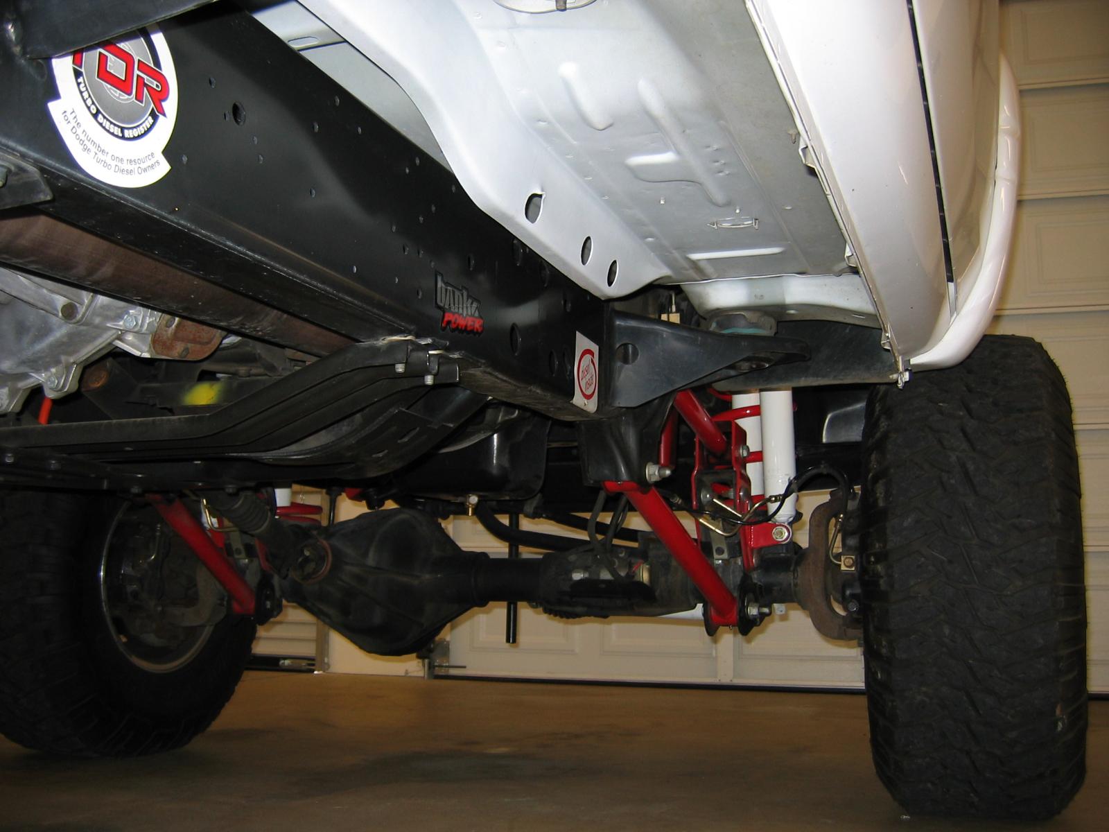
@Doubletrouble you're correct, this truck has accumulated less than 3000 miles since 2009. It was parked in the garage and driven on weekends just to show it off. The 2000 square foot garage was constructed specifically for this CTD and was environmentally controlled...to this day, when you open the door to the cab, the interior is immaculate and the smell of the leather reminds one's senses of a new vehicle. As a hobbyist in the CTD 2nd Gen Cult club, I prefer to tinker all day long and NOT get my hands dirty. Most diesel enthusiasts find my insanity appealing...the sub chassis has the equivalent appearance too. @LorenS sharp Eagle-eye...that L-fitting (JIC) is what AirDog would provide with the "installation kit" to pick off fuel pressure delivery from the lift pump. A short quality rubber line delivers the fuel to a diaphragm isolator on the firewall. I use 50/50 antifreeze plumbed to the internal Fuel pressure gauge in the cab. The photo is deceiving due to angle and lighting. I was mostly concerned about @Timburrr and how he was rewiring his DC, I wish his efforts to be successful without error. W-T
.jpg.da76d0ddfaa625d5ad38d1cf9befce37.jpg)
-
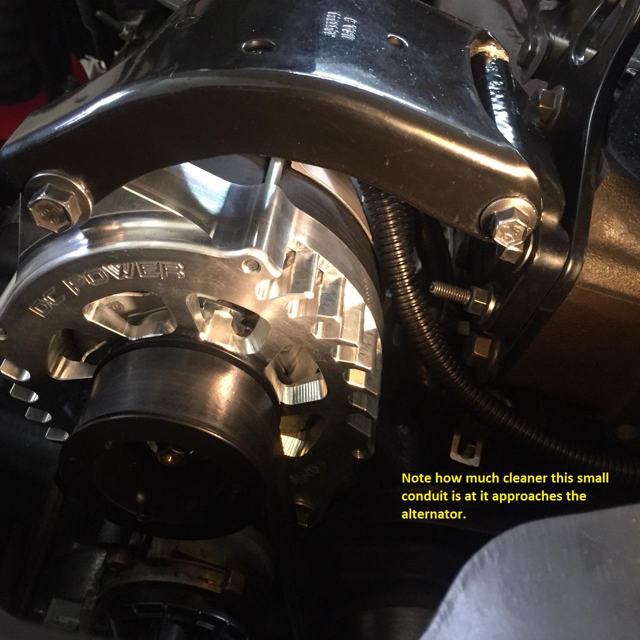
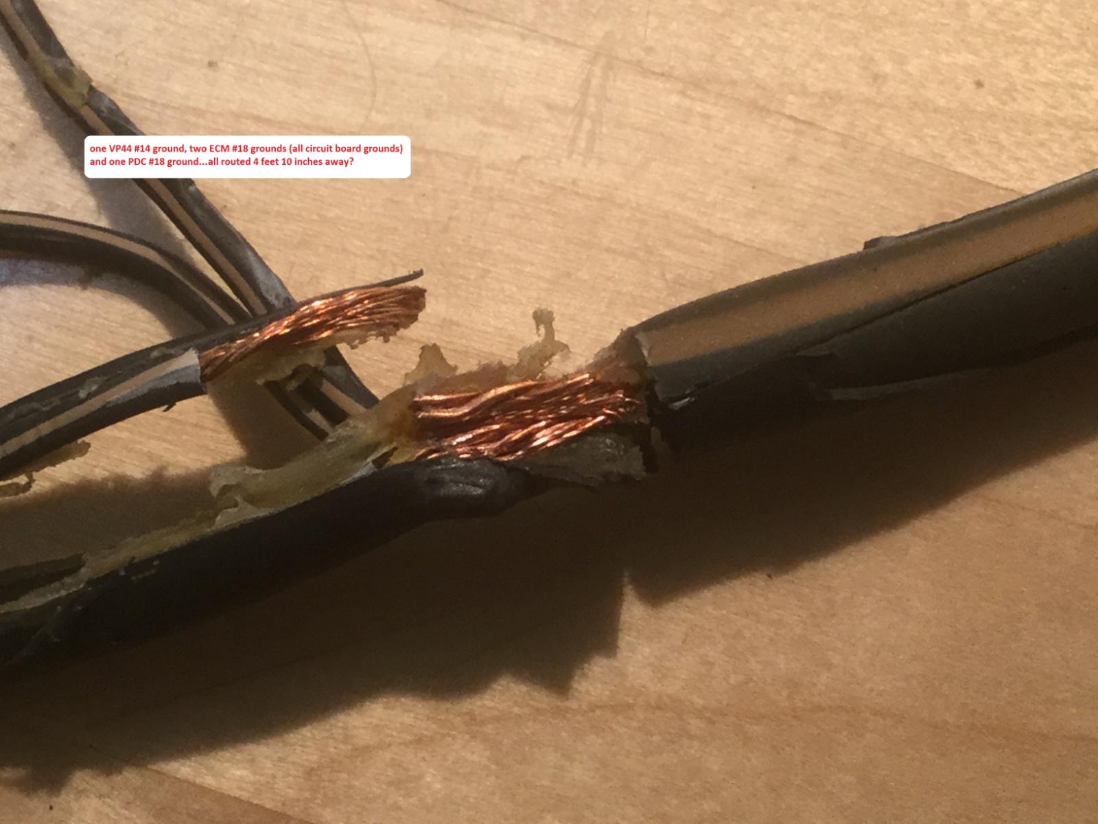
You will have only one robust line, from the drivers side battery positive terminal, connected to the PDC. The alternator + terminal directly feeds the passenger side battery + terminal. All of my high current lines are #4 gauge copper welding cable. Note the single #4 gauge connected to the output terminal of the alternator is a short run directly to the + terminal of the auxiliary (passenger side) battery. There is NO high current wire passing in front of the engine within the loom because you have removed that OE line in this modification. The only wires within the loom are: 1) two wires (blue and green) that control the alternator 2) the air conditioning compressor clutch control line 3) the water temperature signal line This simplifies the loom and you can eliminate the "fat plastic" loom with smaller diameter plastic tubing to enhance appearance. You presently have a single #1 gauge running across the top of your radiator between both batteries. This single robust line connects both batteries in parallel at the positive posts. The negative parallel connections between both batteries is provided by chassis and engine block grounding. If you wish to perform this entire modification correctly, you double strap both batteries into compliance. This is the correct method in order to fully "parallel" both storage cells. The "double strap" method is the engineering standard to provide absolute error free paralleling of large storage cells. The OE factory method was applied because it's cheap and dirty. Multiple connections at the battery becomes difficult, batteries that provide top and side-mount connections makes the job easy. You are creating a power supply and removing errors that arrived from the factory. This modification was to remove the high current charge line of the alternator and eliminate "ripple" noise generated by the alternator from sympathetically entering the small signal leads within the loom that causes other electronic errors. This modification eliminates the haphazard "crush-splice" procedure sealed in glue and shrink-tubing. This modification provides correct grounding methods for the ECM and PCM. The PCM relies on the battery temperature sensor under the drivers side battery to calculate charge rate. Double strapping both storage cells removes any error and places both cells at absolute equivalence to assure the PCM is receiving absolute temperature data in a "parallel" charge configuration. The batteries are to be treated as a "single" source of energy, this method is military-space junk hardened and represents technical excellence. W-T
.jpg.9066186842bcb3a5428bf2d0cd541518.jpg)
.jpg.ed9d95996db640ae93888fc76470078b.jpg)
.jpg.97c20a43a59240a3076f017d8c71733d.jpg)
-
@Timburrr Caution, please re-read the instructions. The +12 volts from the drivers side battery is supplied to the PDC. It's a short distance, less than 14 inches to reach the positive terminal on the drivers side. You can use a short piece of #6 gauge to supply the PDC directly from the drivers side and you will have no issues. W-T
-
Yeah...John @Tractorman brought a few aspects to my attention that need clarification to this issue for @Doubletrouble The run-time for the lift pump in a freeze-up situation is dependent on how hard frozen is it? Also, where is the frozen obstruction or resistance? My error in stating "Let the Raptor Run" is not fully correct and needs to be tempered in application. BTW...prior to applying a new lift pump installation on my vehicle, I would use this "TEST lead, force run" procedure when I would change the fuel filter in the Stock Filter canister. This simple maintenance procedure always evacuates the fuel within the canister as you remove the filter element. Once done, I'd reapply the cap and tighten to prevent leaks. Knowing, I had air in the system, I elected to "force run" my lift pump to purge the system prior to starting the engine. This procedure actually trained my "ear" as to what was occurring within the circulatory system by the way it sounded as it hydraulically chased the air from the system. It is a subtle but, very profound audio report and you need to experience this to gain the auditory perception of its action. It is also an advantage to have a working fuel pressure gauge to visually monitor "what you hear" as the hydraulic system stabilizes. Viewing the gauge as you "force run" the lift pump you'll see some wild excursions as the system purges the large volume of air and begins to become a "pure air free" liquid environment. It requires "run time" to actually hear the system clean up...as the lift pump continues to run, you will hear the finalization of complete purge and your system will have a certain sound that is very particular.... it sings it's own song. On initial activation of the lift pump in this "forced run TEST" the sound is raucous and glancing at your fuel pressure gauge instantaneously will be alarming as the needle will slam itself violently as the purge initially is vacated then, you will begin to hear stabilization but, additional run time is still required as the fuel pushes the last remaining air pockets from the system. The entire lift pump circulatory system will adopt it's own sound and remain at that same sound once fully burped. This "TEST force run" of the lift pump with the engine NOT running is an enlightening experience and one should know the "song" of your system. Each system has a different song and depends on what devices are selected in the assembly. I know that Dan @IBMobile made reference to force running a lift pump in a thread sometime back, so this TEST procedure is not new. Flow through is important, even if its just a dribble of fuel indicating liquid fuel is present within the vane cavity of the transfer pump. My blanket statement to @Doubletroubleto "Let the Raptor Run" in this "TEST force run" is in error! The examples @Tractorman posted regarding "waxing" in cold conditions is a major consideration where NO flow through is occurring. In a common sense aspect, if the system is gelled-up at a particular location within the system, inadvertently placing your lift pump into a "forced TEST run condition" for an extended period of time could damage the lift pump seals following the love-joy coupling at the impeller disk. I ask forgiveness in following verbal dissertation...if you know the "song" your system sings when all is correctly flowing, you will know when the song goes wrong. The lift pump in a harsh low temperature situation maybe looking into a "dead headed" no flow pathway, if there is just a small fraction of liquid fuel within the cavity of the pump, it will be in cavitation and extended run periods could cause damage. With this cautionary knowledge one would call on a reasonable consideration when placing the transfer pump into extended forced run operation. In my experience, I'd be listening for the song. Knowing of the cold storm situation in the eastern states this winter, there is most likely, additional cold-start event errors forthcoming. I'm originally from Butte, Montana and I've seen -60 F however; my 2nd Gen has only seen -20 F and I had no errors. Humble Respect, W-T
-
John, of course...I'm just doodling in the office. It's early Christmas morning and still sober...not for long